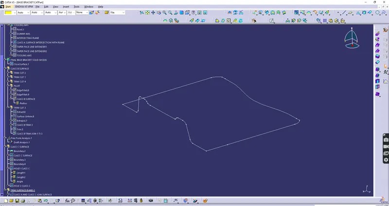
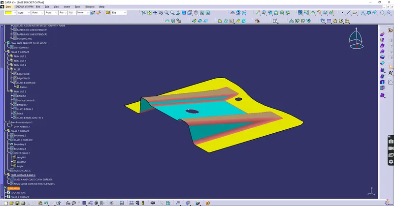
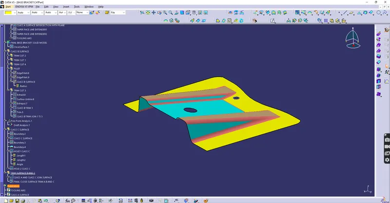
Week 8 - Challenge 1 - Base Bracket Design
Draft Analysis On Class A Surface
In the automotive industry, several steps are followed before finalizing any design. The initial Phase is Sketching where all Artists and technical teams come up with different sketches. some of the sketches are selected and proceed for Clay Modelling and Clay modeling to ensure the outer geometry and aesthetics of the product, after complete clay modeling the 3d scanning file will send to a CAD designer to make further assembled models. In this area, we get the outer Surface Design called CLASS A Style Surface. Based on this Class A surface we have to make Class B and C surfaces and Joint ABC Surface proceed for Mould design and then for Moulding.
Before Designing CAD Designer Ensure Received Class A surface is Appropriate or not. So Following test analyses are conducted on Class A Surface
- Draft Analysis in Visible and Mtr. mode
- Tooling and Feasibility check
- Fork, Join, Tangency, Connexity |check.
- Missing Surface, Extra Surface Analysis, sharp Edge analysis
- Graining Analysis
- MTD analysis, Undercut Analysis
- Gap and Flush Analysis With Environment. MTM Condition Check.
As Draft Analysis Done For Getting FEasible Solution where the surface is okay with all required Conditions or not. In particular Casting Process Where Mould has been removed from the Cavity, We have to ensure there should be a Certain Angle that Ensures While removing part the edge surface will not be damaged and minimum Contact will be secure.
Injection Molding, Casting In all Processes Where Product is made from Mould We have to Consider Draft angle to ensure Minimum surface Contact, and Maximum Surface Finish with Minimum Wear and tear in Product. In Industry Minimum Draft angle is 0.5 Deg Cel. Draft angle also Depends on Selected Process For Casting or Mouling. Follow PSG Design Data Book- Page 10.4 For Draft angle As per Dimensions. Draft angle also Depends on the Material of the pattern and Also the Material of the Product.
In Injection Molding Tooling Axis is the axis that ensures the exit of the Product From the Mould. Or the Axis Which is Along with the Injection Moulding direction. In this Direction, the Draft Should be considered and All Angle Should satisfy All draft requirements so that product will not fail during molding, otherwise part may collapse.
Draft analysis is a Measure step Followed By CAD DEsigner To ensure Received CLASS A Is Okay for Further Design or if any changes have to be incorporated to Ful fill Missing Properties. For Draft analysis, We need to Find the Tooling Axis Direction and Accordance with the Tooling axis Draft analysis is done On Provided Class A.
Method to Get Tooling axis
1. By Using Bisecting method where One of the main Locational Parameter Is Selected which covers the maximum faces of the surface and considers all bends and surface directions is selected as per the axis system.
2. Normal to Product/Part/Feature Face, In this Method Product Center of Gravity, is calculated and this point is taken as Reference if all Part faces are facing in only one direction then this method is useful to find the tooling axis.
3. Center of Gravity and Maximum Face direction will give a line that can be used as a Tooling axis.
4. Product/Part/Feature Is Kept in Iso metric view maximum face area is selected for reference Dummy Axis. A dummy axis is created along with any direction and a Compass is placed on that line which rotates by a small gradual change in angle (1 Deg cel.) until we get all faces of part changed to green or satisfy min draft required. if the desired direction is Achieved then the Compass is locked. and this compass is used for creating a line (main Tooling axis) that passed through the Center of Gravity of parts.
Tooling Axis By using Bisecting Method is shown below
A. Select Face Area or Direction along with Axis Which Includes Maximum Face Area. In the Given Base Bracket, Example Axis Z is Having The Faces Which Include the Maximum Faces of Part.
B. When a Proper Face area Is Found We can easily assume the Direction Of Tooling Along with that axis. But before Finalizing the axis we have to find the proper locator for the axis. in Several Model Circular Holes, Slots Cuts or Plane Face Mid Point Can be Used as Locator
C. After Selection of Locator We have to create a point.
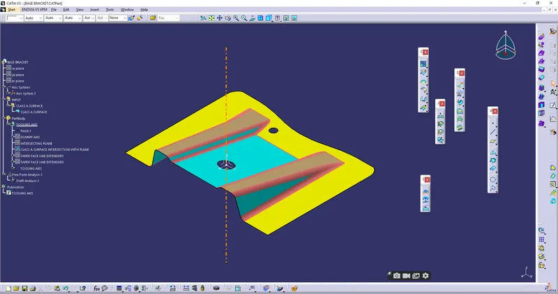
D. Create Dummy Axis Line by using the same Point and Perform an Initial Draft analysis on Surface
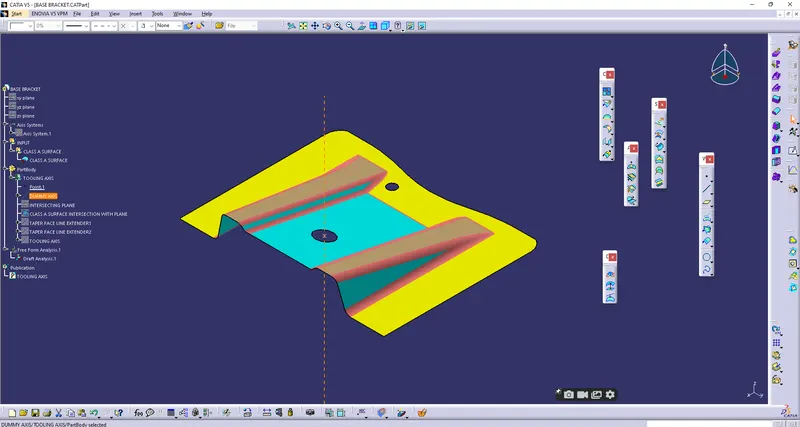
E. In the dummy Axis It does not matter all Faces should satisfy the Draft requirement because It is just for the Confirmation of the Direction of the Tooling axis. after we ensure maximum faces are satisfying the draft then we can create an axis system on point and then plane which along with the direction of dummy tooling axis.
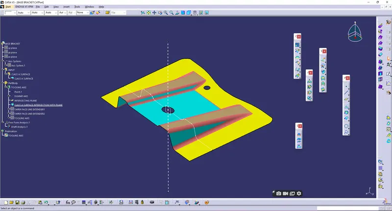
F. Create Intersection lines of Part On created Plane.
G. Find the faces which are In symmetry or create an intersection with the tooling axis.
H. On the same lines Create another line and extend them.
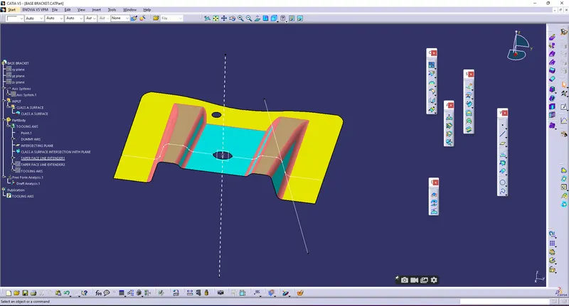
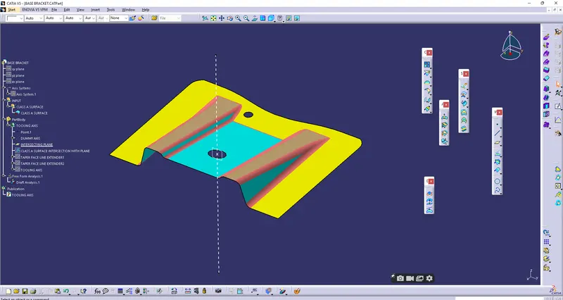
I. After All line select line command and Create bisecting line. select both symmetrical or intersectional faces of part lines and select point one line will be created renamed as Main Tooling axis and Isolate it or Publish it.
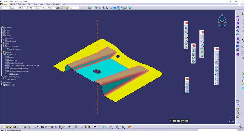
Draft Analysis in Catia
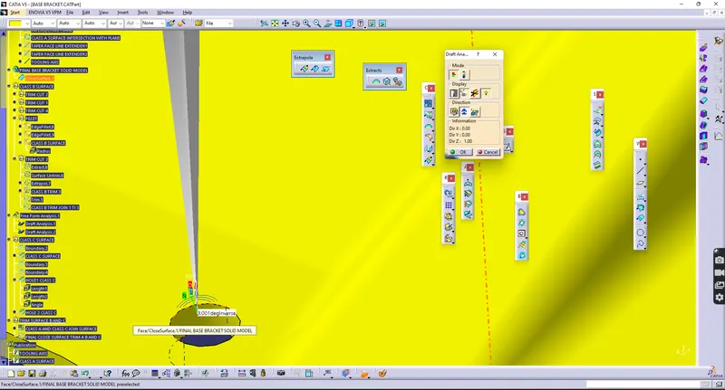
A. Tools > Analysis > Featured Based Analysis > Direction >compass > (Drag Coordinate Compass to Tooling Axis)>
select a Surface face and ensure You have entered the minimum Required Draft angle in the small pop-up window.
Check The Color of the Part.
in Given Surface Minimum Draft Required is 3 Deg Cel. As Per Given Condition Part Passed Draft analysis Concerning selected Tooling Axis
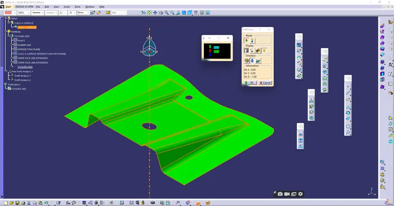
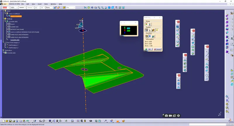
Draft Analysis in On Final Part Body
Tools > Analysis > Featured Based Analysis > Direction >compass > (Drag Coordinate Compass to Tooling Axis)>
select a Part face and ensure You have entered the minimum Required Draft angle in the small pop-up window.
Check The Color of the Part.
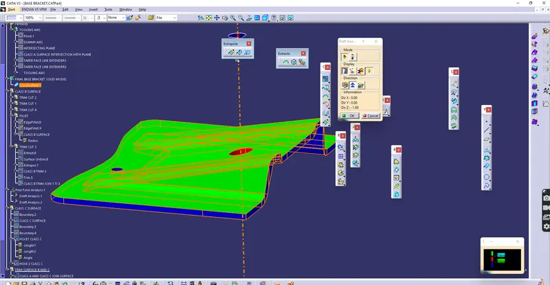
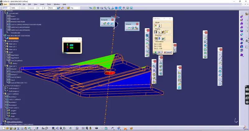
As Green Color shows Part Face is Passed the minimum draft angle test. as Blue Color Indicates a Negative draft angle of -3 deg cel.
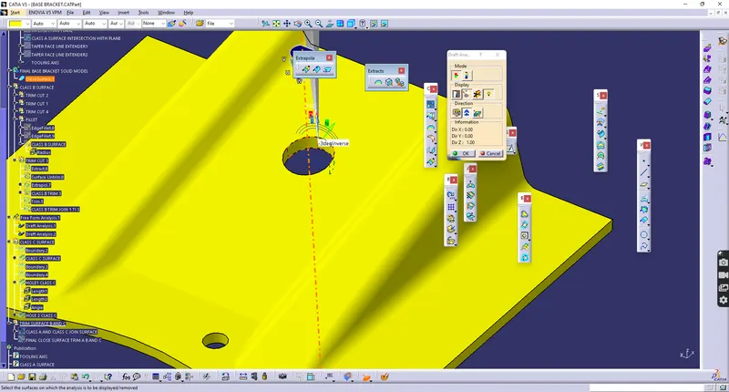
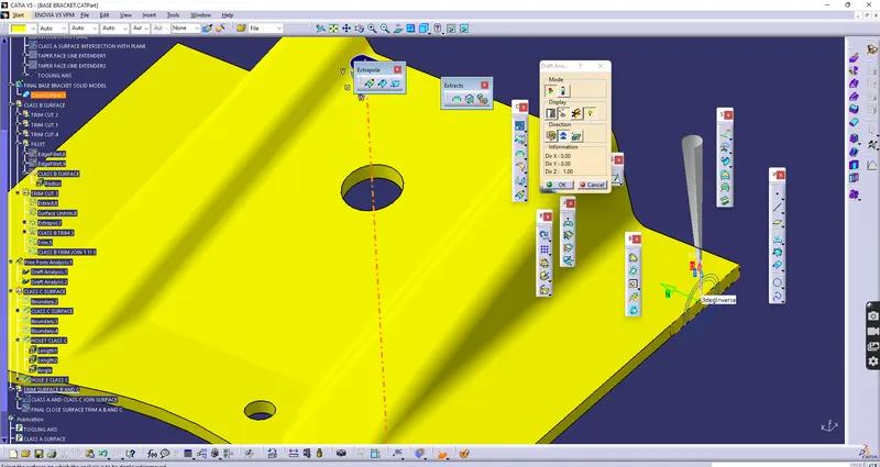
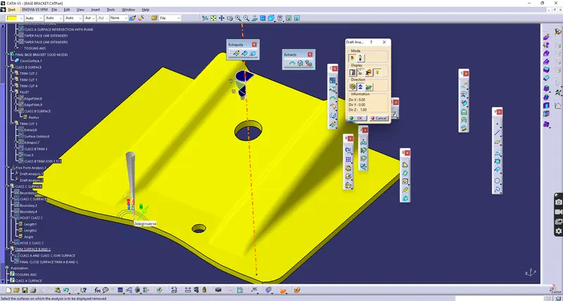
"fly on Mode" Show angle when we hover the mouse pointer on any particular face.
Exercise File
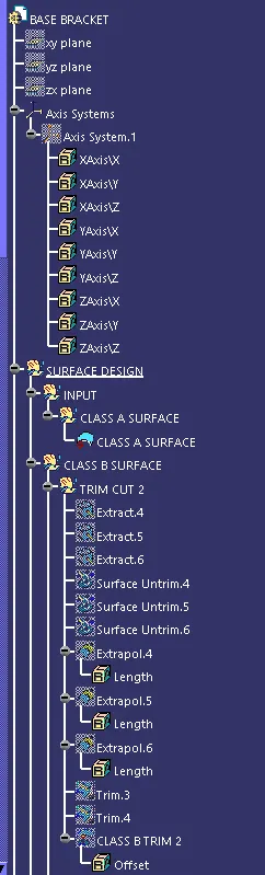
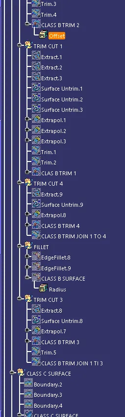
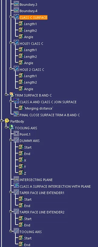
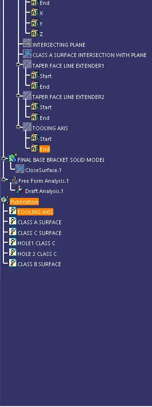
1. Feature Tree
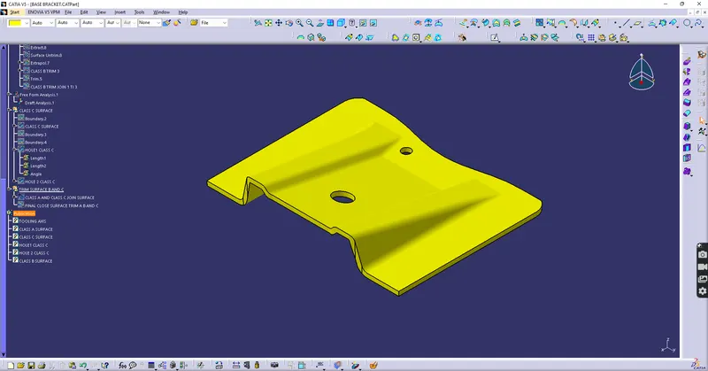
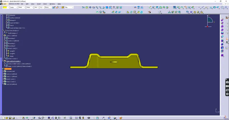
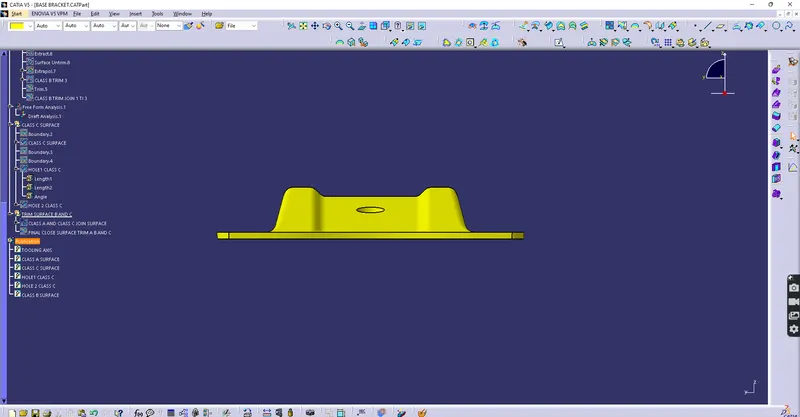
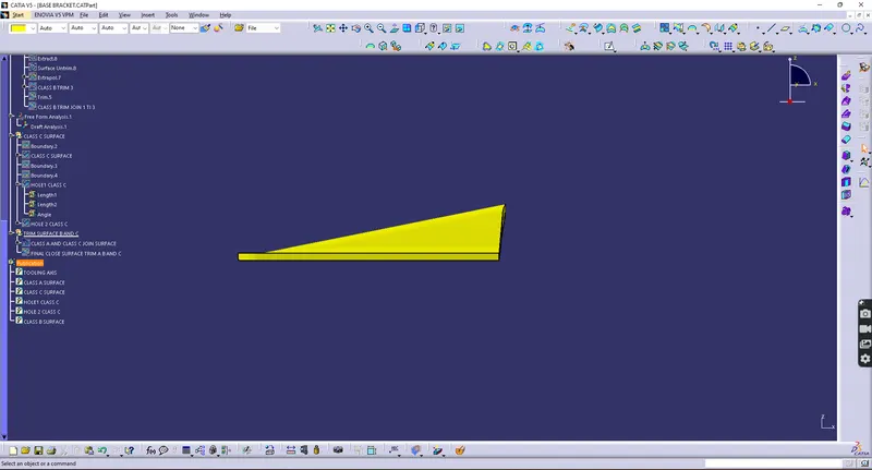
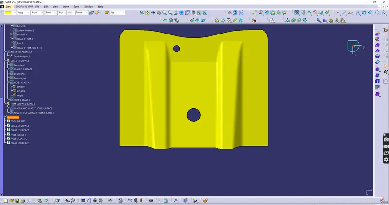
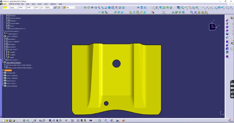
2. ISO, FV, TV, and SV.
3. Boundry Sketches