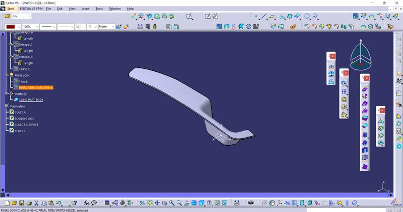
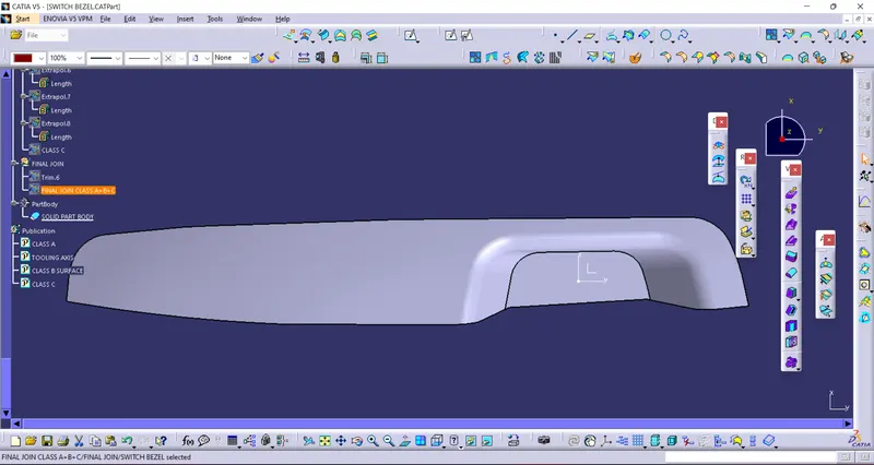
Week 8 - Challenge 2 - Switch Bezel Design
Dear sir
Please Find Challange 2 Files Below
Title:- Creation of Switch Bezel Base Thicken Part
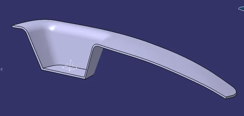
1. Creation of Tooling Axis
A. Tooling axis is the axis that gives the direction for inserting molten Fluid from Injection Molding or casing, this ensures our part body should prepare without any failure.
B. Creation of tooling axis depends on three parameters, minimum angle given for draft and molding method.
C. Bisecting Method is used To create an Appropriate Tooling axis.
D. Bisecting method for Tooling axis
I) Select the Base of the part of the face which holds maximum walls and other faces
II) Create a point on the face
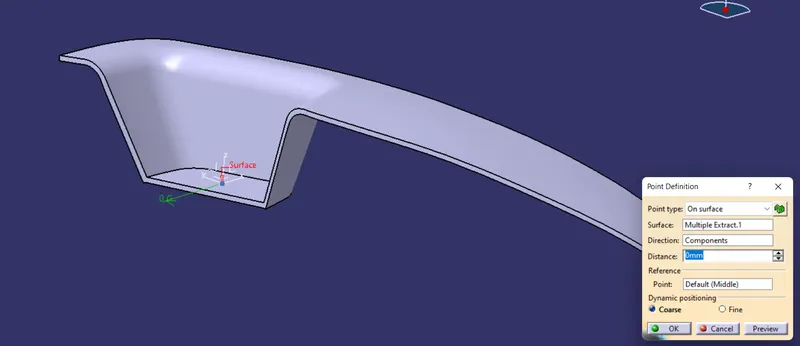
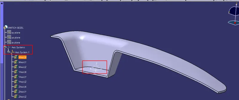
III) Create Axis System on Point (It will be as Per Class A Generated)
IV) Select a Formal Plane Which Includes Draft Faces And the Plane Should be Perpendicular to that Face. Create Sketch on Taper face and Generate Bisecting line( Bisecting line:- Two lines Are selected and the line which forms in between them goes in the same direction) If there is no Taper face At another side try to make line by using point and Angular Dimension in between parting line (angular dimensions is adjustable as per Result comes in Draft analysis) We have kept Dimensions as 5 deg. Cel.
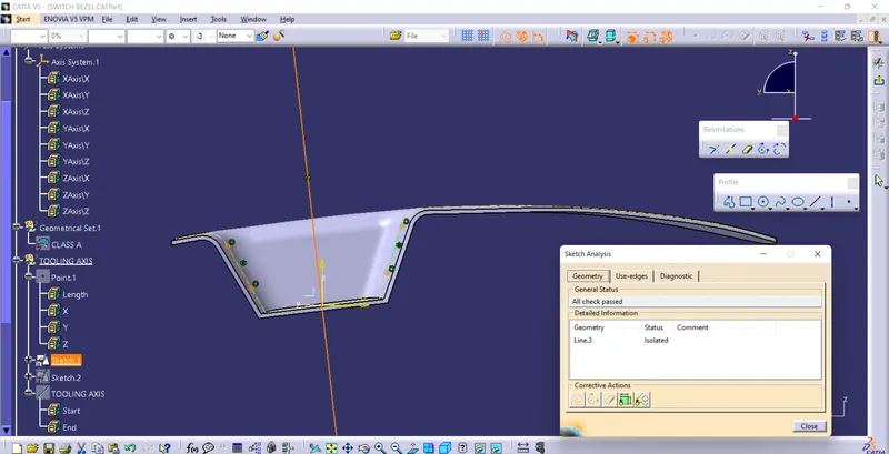
V) If the part has an Unsymmetrical face then Go with another Plane Which Holds a Taper Face and the Plane Should be Perpendicular
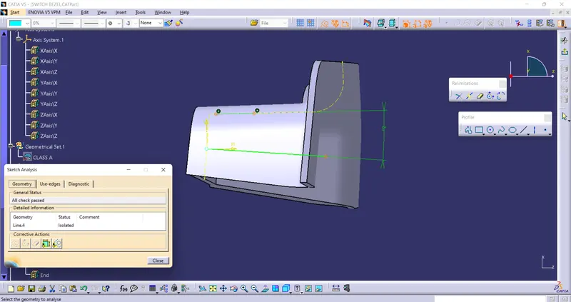
VI) Create Line Bisectiing to both Sketches which actually Bisecting in nature to Particular plane.
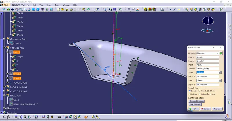
VII) This Created Line Named As Tooling Axis (now its ready for Draft analysis)
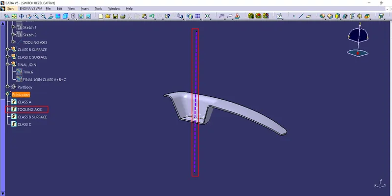
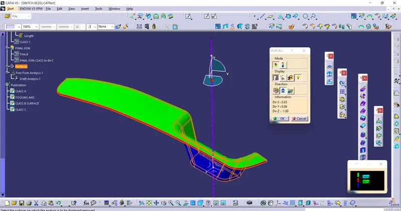
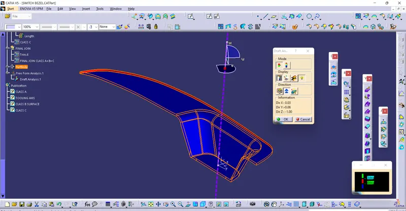
2. Draft analysis On Class A surface
A. Every Design Software has this Draft Analysis Feature. The ultimate aim Is to make the Part body or surface Ready for Molding. Also, Draft analysis is mainly done to select the proper and appropriate Tooling axis.
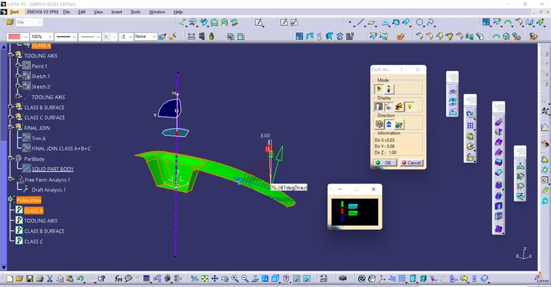
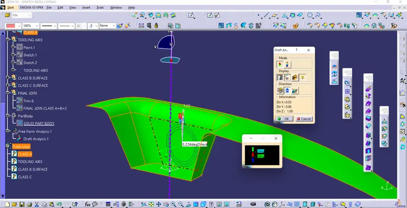
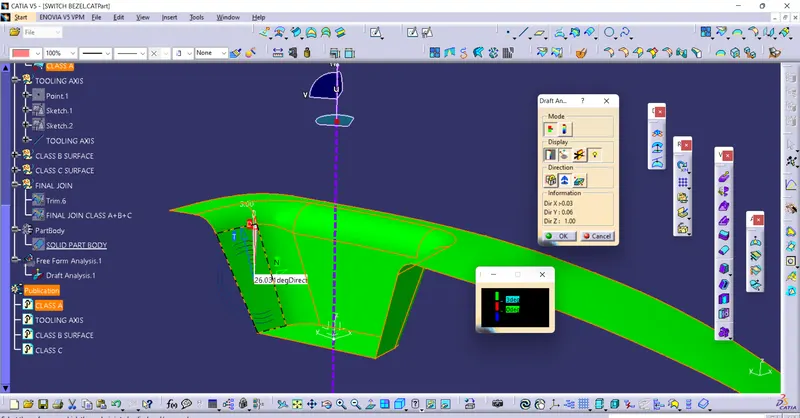
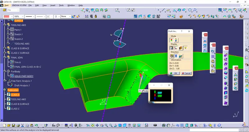
B. As per the following image, all Faces are in Green (3Deg to 0 Deg) Means the Tooling axis satisfies Angular Priority and we can ensure the tooling axis by keeping it in a Normal view All faces should Be visible As shown in the image.
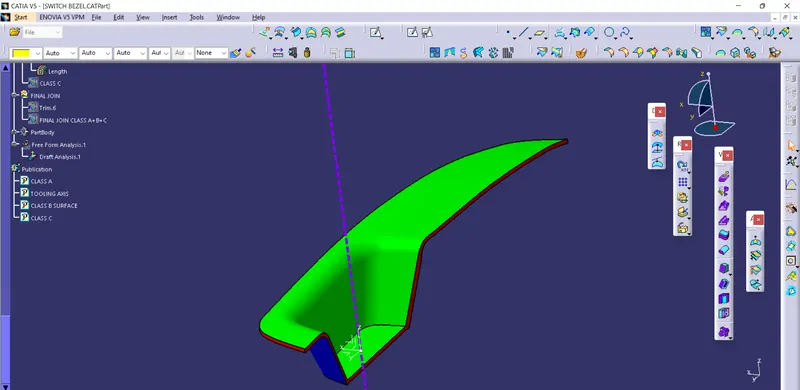
3. Draft analysis On Solid Body
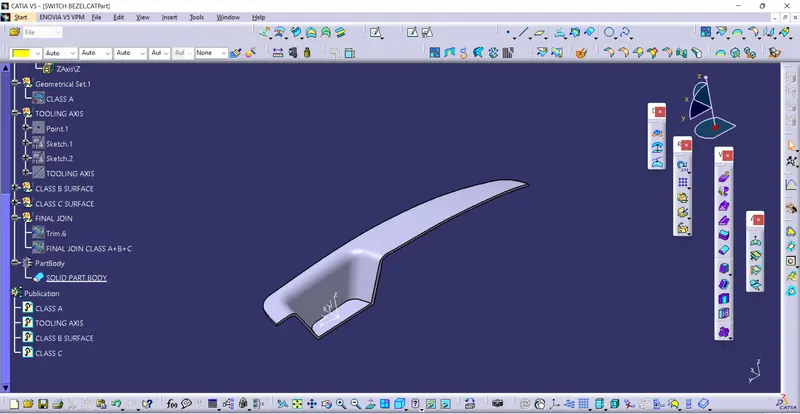
A. As per the following image, all Faces are in Green (3Deg to 0 Deg) This Means the Tooling axis satisfies Angular Priority and we can ensure the tooling axis by keeping in a Normal view All faces should Be visible As shown in the image.
4. Class B surface
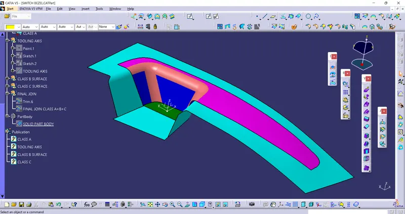
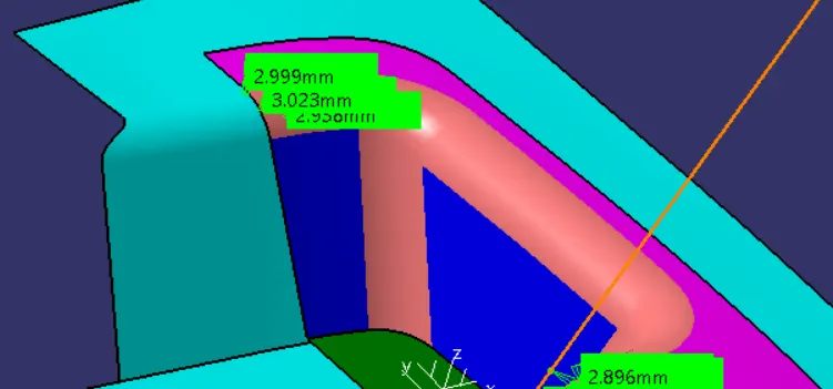
A. Ensure Consistency Wall thickness
B. Avoid offsetting Fillets and Untrim If the fillet unable to measure
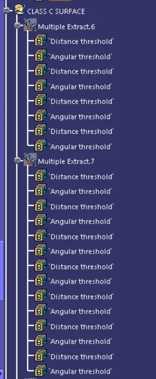
5. class C surface
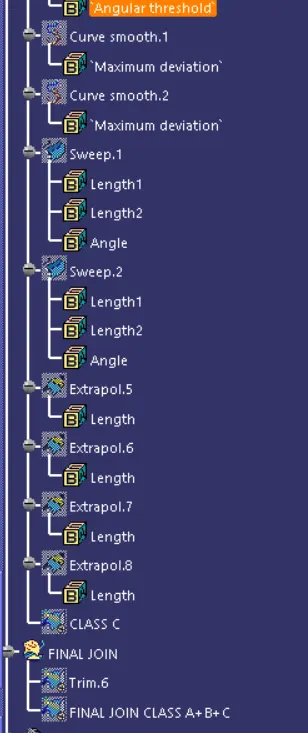
A. sweep Along with Tooling axis and Minimum 3 Degree draft should be given
B. use a smooth curve with 0.001 deviation allowed
C. Class A and Class C can create problems at edges where multiple patches will form this can be avoided by extrapolating Class A surface by 0.1 mm or sweep at both side and trim will ensure automatic Extrapolliting
6. Solid body
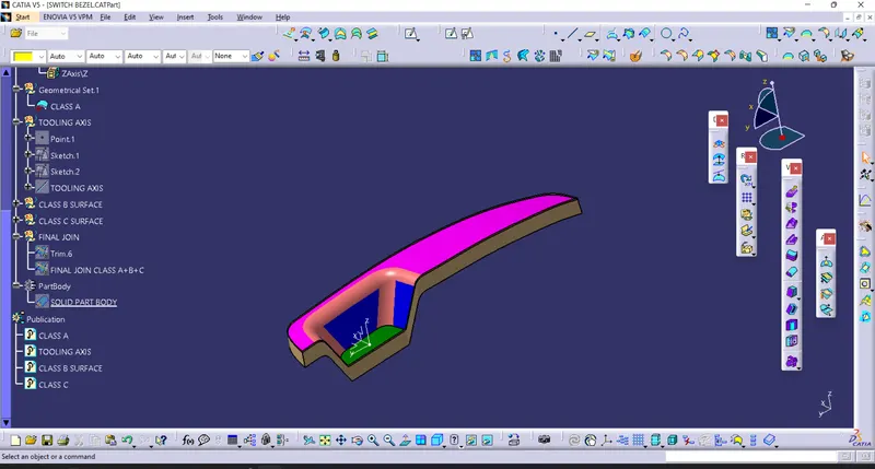
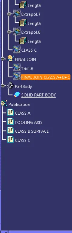
A. Ensure Boundry will not be formed after Merging Class A and B and C surfaces
B. Create Body in Part Design
Part Details
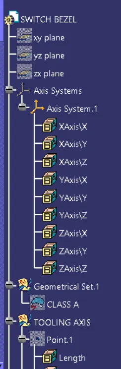
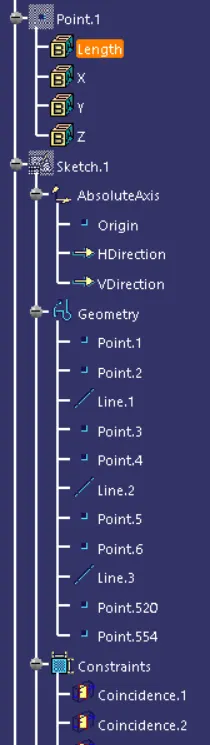
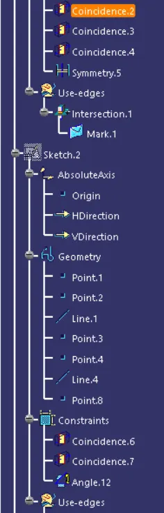
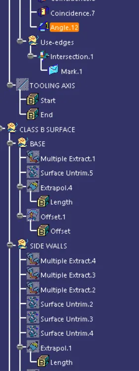
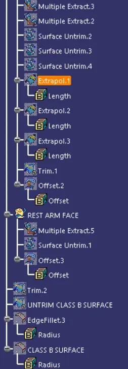
A. Feature Tree
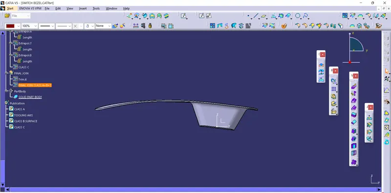
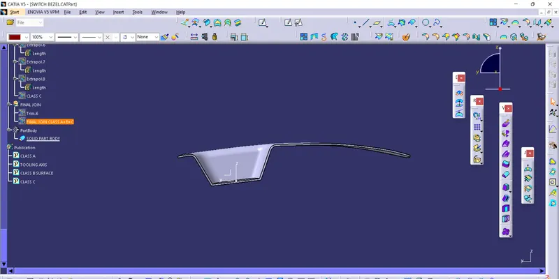
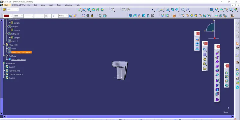
C. ISO, SV, FV, etc.