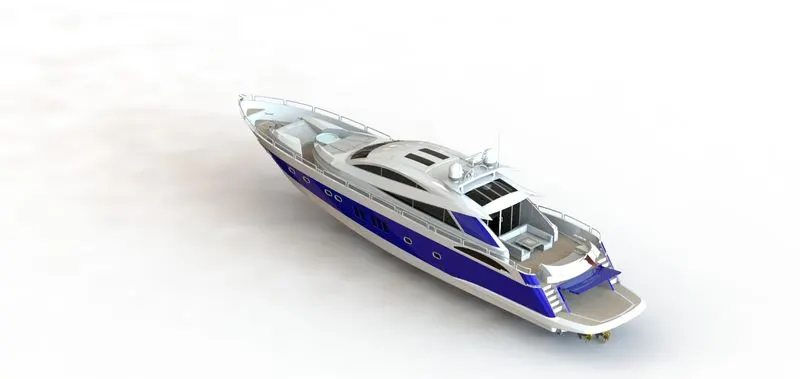
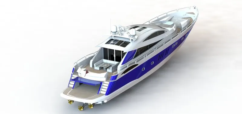
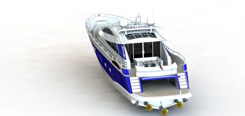
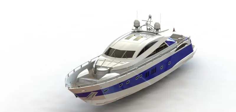
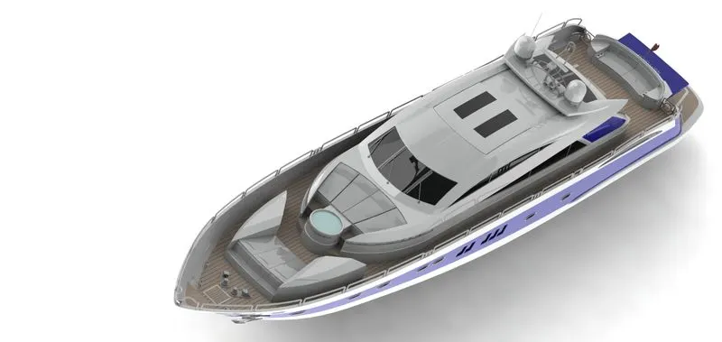
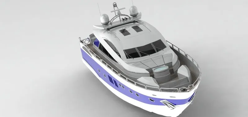
Radar Mast & Final Assembly of Yacht
Detailed Report on Yacht Design Project.
Title:- Enriching Skills with Yacht Design
Objective:- The objective of this design is to get familiar with software tools and understanding different concepts of software tools in brief, like Surface tools, Part modeling Features, automated assembly concepts, design methodology, Aesthetic design, and Appearance Detailing.
Introduction:- This Design Is basically focused on making "software tools" more familiar with the user and design complex geometry using surfaces. while learning many automobile vehicles came with aesthetic look and curved attractive superstructure, this is possible using a surface tool which gives better productivity while designing such complex curvy models. For Designers Solidworks came with lots of tools so it's difficult to remember them and this course brings quick revision of those tools very effectively.
Design Methodology:-
The yacht is a complex and unimaginable part without any prior knowledge and experience, so basically, it needs drawing supports where it can be sketches or images, the course came with an initial blueprint set up so we can imaging what and how design is going to make. blueprints allocate front, top, bottom, side (mid), backplanes with specific distances. to avoid any particular details. the yacht is divide into several components according to its respective placements, all list is mentioned in parts details. each part comes with detailed sketches and 3d operations to achieve the desired shape. in any assembly or part design three things are more important, sketches, Features, apply geometry features, appearance. sketches are the backbone of any design where it can be simple or any complex geometry they require base sketch in drawings.
Sketches.
1. sketches should be fully defined
fully defined sketch always makes the software easy to handle final graphics without any rebuild errors and also helps to maintain designs, sketches can be controlled by equations, dimensions, and constraints.
2. use of maximum constraints instead of making clusters of dimensions.
constrains are basically makes co-relation in between geometry like equal, parallel, fixed, symmetry, perpendicular, etc. this reduce your rework, and helps to maintain stable sketch drawing
3. Avoid Any Error (over defined, unsolved Geometry, Unable to solve, etc. )
its an important learning session for any software used to solve errors while designing, maximum error gives maximum experience and it gives basic benefit where we can reduce error or predicts conflicts earlier so
Features.
1. 3d Features always helped to achieve desired geometry, in SolidWorks, we have different tabs to achieve any 3d geometry, feature, weldments, surfaces, sheet metal. they are used according to design needs, in this course we have covered 3d most useful feature commands.
2. as the yacht comes with challenging curves so it should be handle with a lot of drawings and detailings so we need to come with surface features which having very fine thickness so handling surfaces is easier and operations make more achievable.
3. this design is going to cover maximum surface features and helps to understand how surface helps to achieve any complex geometry, tools are lost easier and come with additional settings like, knit, merge, tangent, the normal direction inside any 3d feature which we are using.
Geometry Features:-
1. to get a smother corner and aesthetic look most of the tools are useful, like fillet, chamfer, liner pattern, mirror. These are also called part base features which did not require any base sketches.
2. Any detailed drawings are possible with these commands which always give a stable and attractive look. Sometimes during analysis, these features help a lot, like ribs in many heavy structures, is a part base feature, with only one additional detail we can achieve a reduction in cost and improves stability and strength, fillet or smooth corner helps to avoid any stress concentration at corners, chamfer at corners always preferred for safe handling.
3. some time extra detailing is discarded because of the family base assembly or configuration and to reduce file size and any graphics concentration during large assembly loading, simple example of this we are not getting any threads and cuts in smart fasteners to handle its graphics area fast and reduce laggings during any operations
Appearance:-
1. As per design needs user gives an appearance based on material or without material, lots of industries are worked in metallic parts so the material is applied accordingly to use further in analysis and simulation, and in some cases where only part looks is the main objective, so the clear and appropriate appearance is important.
2. in this course part base appearance is applied which basically gives a better understanding of some features like using appearance library and decals to achieve desired and realistic looks
Most Of the patterns and PRE Prototype stage includes Part modeling of design, like its costly where to get physical prototype digital prototype may prefer for any future consideration, part modeling basically means they are come without any engineering aspects, real dimensions, and most of the parts are design with appropriate proportion. this is one of the stages in design thinking where instead of 2d sketches 3d model is drawn and it helps to get our final design. this course may not include any manufacturing details or any detailed dimensions, tolerances limits, analysis, curvature details , this all is the later part where the final drawing is made for manufacturing.
To get a creative approach to meet client needs, unique design always comes with part modeling in any software so basically, this course will prepare you for design in a free mindset and helps you to achieve any design you like.
Design Methodology for Yacht:-
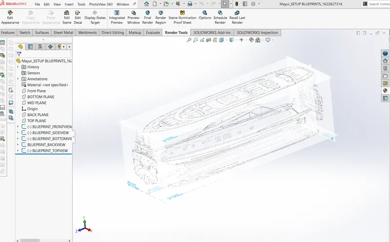
Setting of Blueprints
1. It's an important step while designing we need some sketch or image support to check our design goes in the right way and it's also important while the complete model should look aesthetically correct.
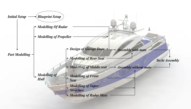
Description of design:-
Parts of the yacht:-
1. Radar
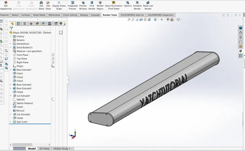
(For Detailed Images Click Here)
2. Propeller
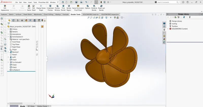
(For Detailed Images Click Here)
3. Hull
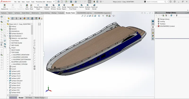
(For Detailed Images Click Here)
4. Garage Door
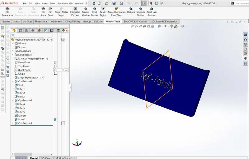
(For Detailed Images Click Here)
5. Superstructure
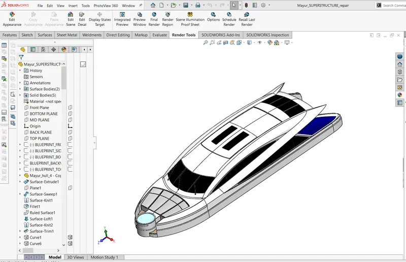
(For Detailed Images Click Here)
6. Front Seat
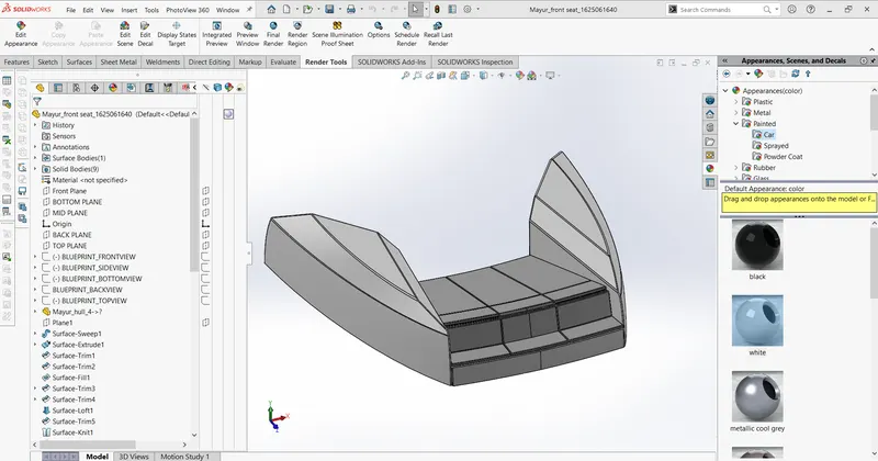
(For Detailed Images Click Here)
7. Middle Seat
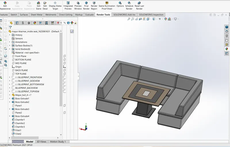
(For Detailed Images Click Here)
8. Rear Seat
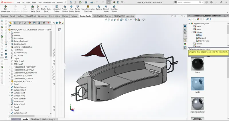
(For Detailed Images Click Here)
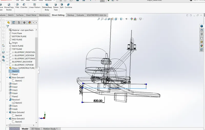
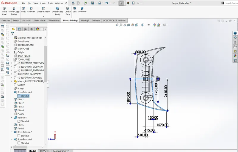
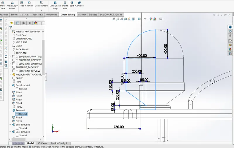
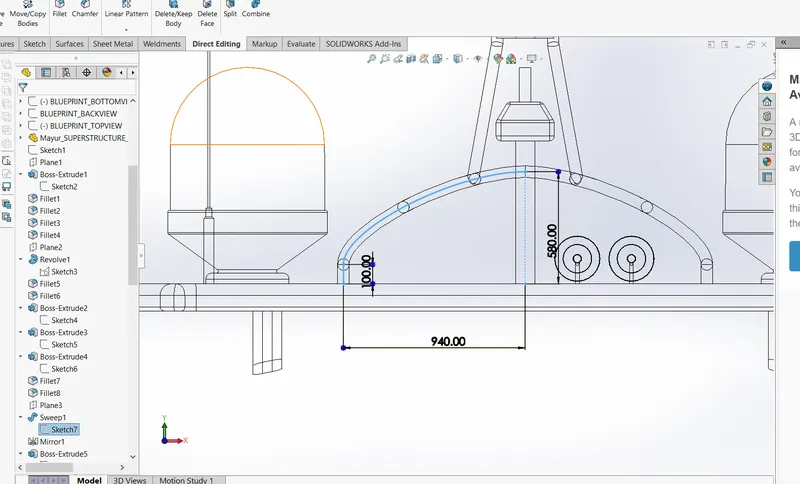
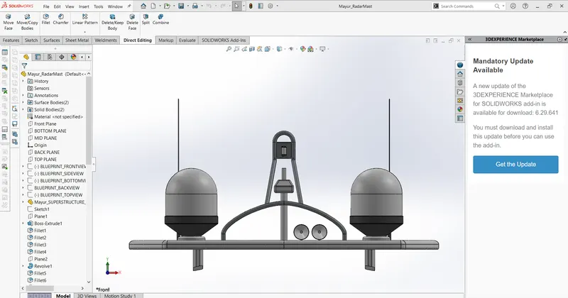
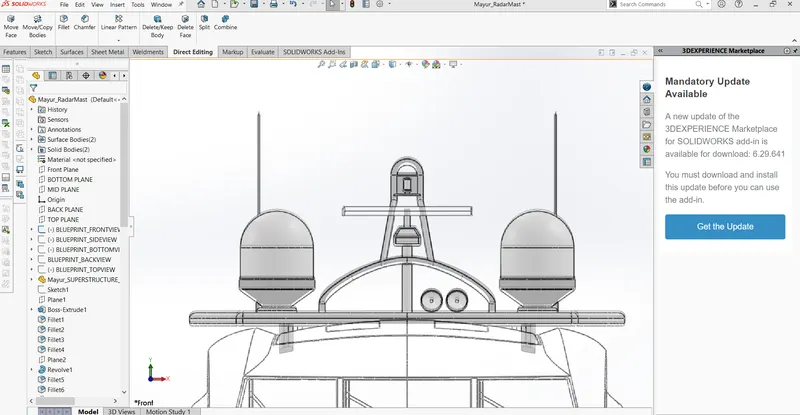
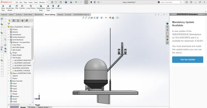
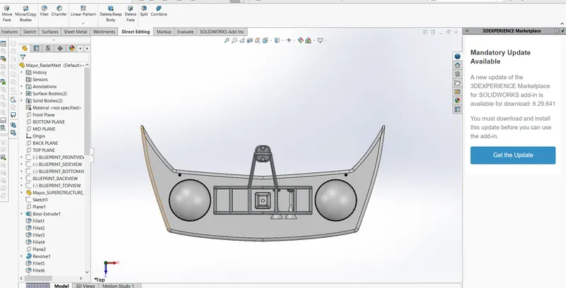
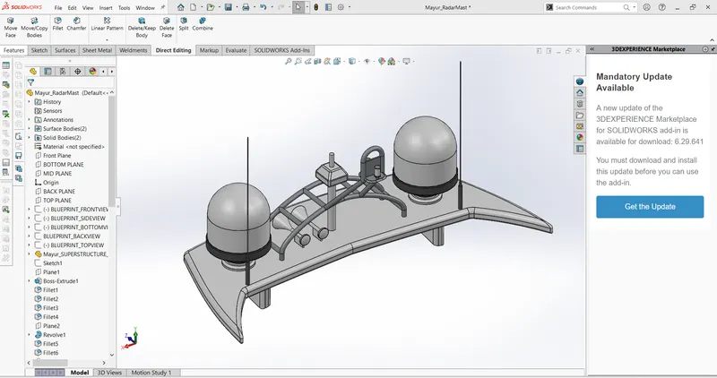
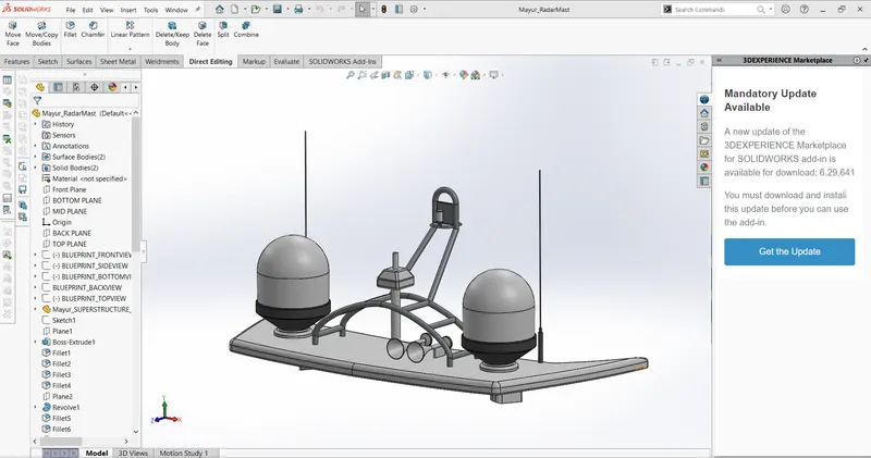
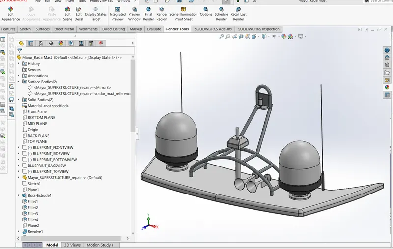
9. Radar Mast
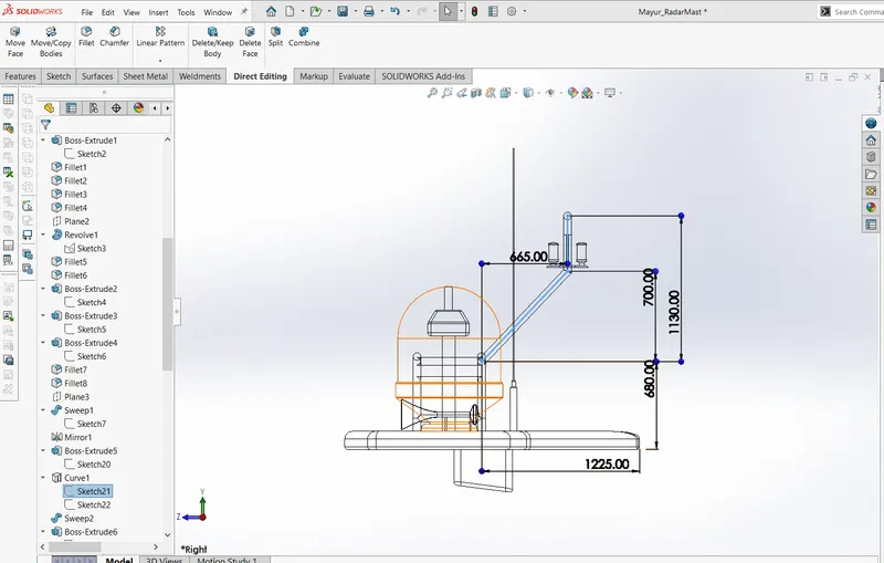
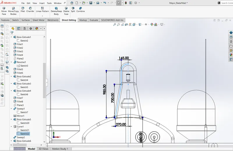
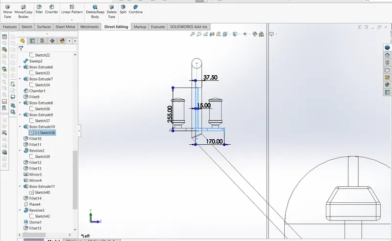
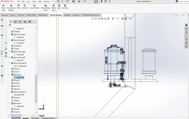
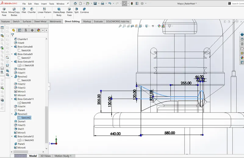
a. Sketches
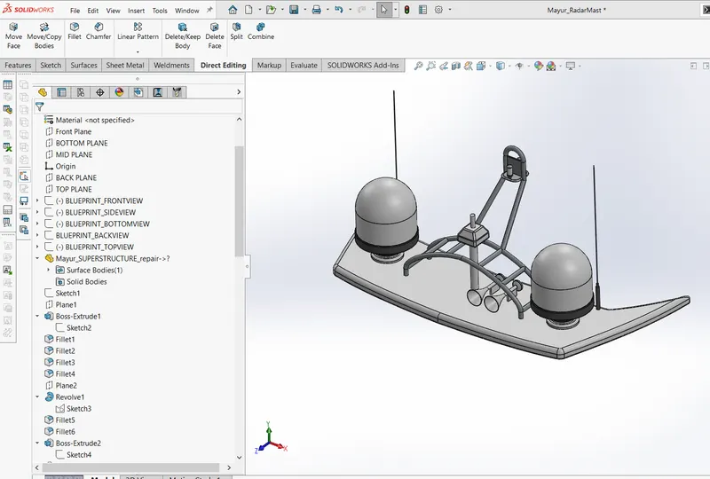
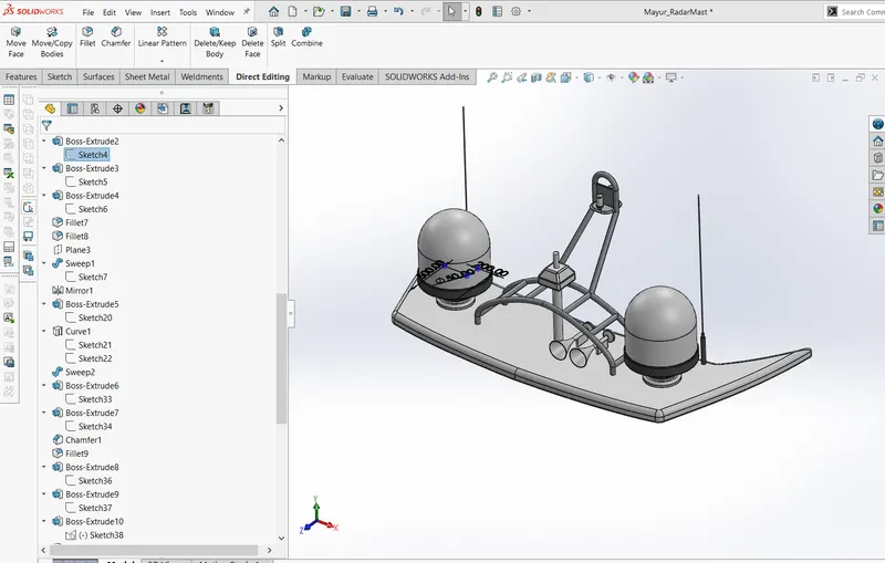
b. Feature Tree
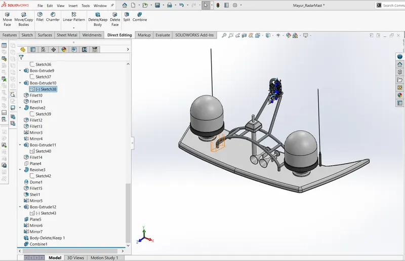
c. FV, SV, ISO view
Solidworks Commands:-
In this whole design, we have to use lots of tools so it should be explained in tab wise as per Solidworks user interface
Sketch Tab:- In this tab, we have lots of sket entities options. line command which gives us better control with straight geometry, construction lines always becomes an important part for sketching, and splines are always made curvy structure possible. so all these tools come with control parameters which we are going to study in this course. Some Effective designs are always Base on 3d Sketch which achieves by sub-command in the list of sketch tab.
Feature Tab:- 3D Operations comes with features tab where simple boss extrudes creates solid body and cut feature performs desired cuts in solid body, loft boss has and sweep boss base help to get pipe structure in this design, it becomes easier in earlier Solidworks versions, where we need to just click on circular profile and sweep created with diameter input. fillet gives aesthetic curves and helps to maintain the body in appro[priate proposition with realistic looks.
surface Tab:- surface help to achieve complex geometry and always designer use to make complex or some 0 mass body using surface commands, extrude, sweeps, extend, ruled, offset, trim are the key commands during the whole course.
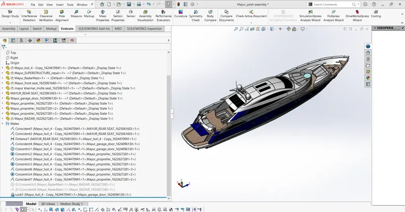
Assembly of the yacht:-
In any design, the assembly can be done with parts, or subassemblies, imported models, components, etc.
way of doing assembly can be different where each part is designed individually and save them for future assembly, in other condition whole assembly is created in the part file as a different solid body and save this file in assembly format so each part gets fixed/ attached as we created.
The relative concept, where you create some base feature for your next part and import and redesign so you can achieve automatic attachment of parts in an assembly.
in this course relative assembly is considered where the full design includes curved and complex geometries so it's difficult to achieve mates to get this done properly or it can take longer time, to avoid this, the concept of the base part/ feature is created for next assembly part so we can make sure we are going to get desired assembled model.
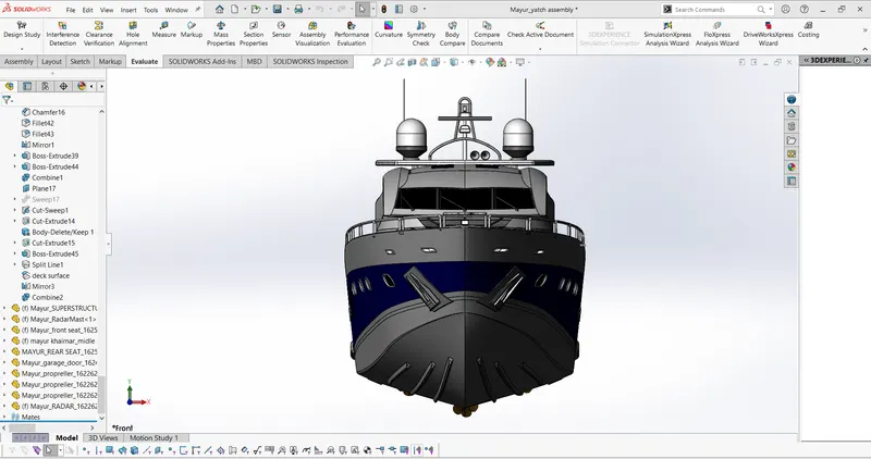
1. Views
a. FV, SV, and ISO
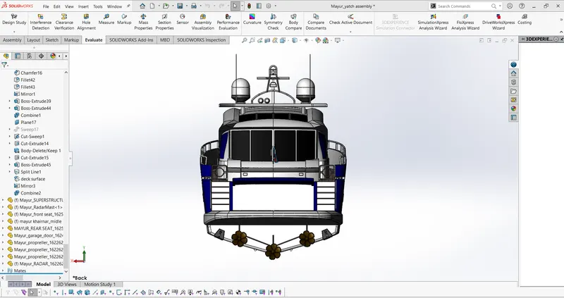
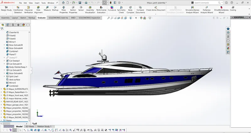
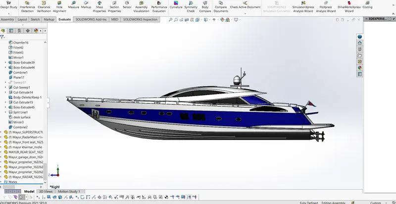
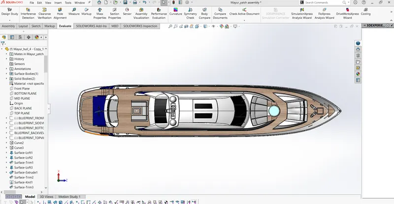
2. Mates
a. Most possible way to get parts to allocate properly, to maintain relationships, mates are useful, in this model detailed mates are not discussed but the possible way of attachment is done with standard mates.
b. Exploraring Mates is one of the wide concepts in model assembly, motion analysis, gravity, testing, etc. all these different factors depend on mates, some additional details like smart mates are also the best approach to get mates done where if the part came in contact with parent part it will be attached automatically, the best example of this smart mates is tools inside Solidworks library.
c. mates used in the model
1. Coincide
make faces, planes get attached together with zero distance
2. Concentric mate
this mate coincide axis of two cylindrical bodies together so they can rotate about the parent cylindrical or circular body
3. Distance Mate
Distance Mate use full to make correlation in-between faces or planes with desired distance, this makes your planes or face parallel and keeps particular distance in between bodies or sub-assemblies
3. Render Images