Switch Bezel Design and Draft Analysis using CATIA V5.
AIM: To create the Switch Bezel Plastic component through the given Class-A surface. To begin with, the tooling axis for the given Class-A Surface should be created meeting the requirements of the draft angle and at the end perform the Draft analysis on the model.
Take the Thickness of the component to be 2.5 mm
OBJECTIVES:
- To ensure proper tree structure is followed.
- Geometrical sets should have a proper name based on the sketches present inside of them.
- All the sketches should be created under the geometrical set.
- Use of the close surface feature to make a solid body from the surface.
- To publish the tooling axis Class A, B and C surface.
THEORY:
- Draft Analysis:
Draft analysis helps to detect if your drafted part is easily removable from the mould (in case of plastic component) or die (in case of sheet metal). All plastic components will have a minimum draft of 0.5 to 3deg. And for automotive sheet metal parts, the draft will be 7deg or more. If a mould wall is perpendicular to the part ejection, there is ample friction or interference between the mould and the part which will not allow one to release from the other. This is why design engineers give a minimum draft to the part.
In CATIA V5 the feature draft analysis dialogue box looks like this:
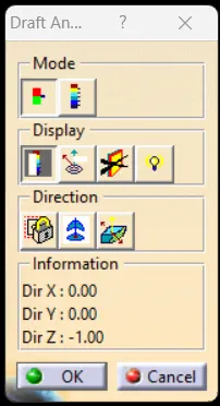
- Mode:
- The mode option let you choose between quick analysis and full analysis mode.
- In quick mode, there are 3 ranges blue, red and green colours. In the case of the plastic component, we will set the draft angle as 3°.
2. Display:
- The first box is to open and close the colour scale dialogue box.
- The second box is the analysis under the running point when activating the checkbOx and moving the pointer over the surface. This option enables you to perform local analysis. Arrows are displayed under the pointer, identifying the normal to the surface at the pointer location (green arrow), the draft direction (red arrow), and the tangent (blue arrow). As you move the pointer over the surface, the display is dynamically updated. Furthermore, circles are displayed indicating the plane is tangent to the surface at this point. The displayed value indicates the angle between the draft direction and the tangent to the surface at the current point.
- Click the No Highlight Representations button to set the display option of highlight effect sources as 'on/off. When checked 'On" the surfaces are selected but they will not be seen in the specification tree.
- Click the Light Effect button and the colours of the analyzed elements react to the light source.
3. Direction:
- The first check box is the locked direction icon which is used to lock the direction of the compass after selecting the specified direction.
- Click on the compass icon to specify the new pulling direction to remove the part.
- Click the Inverse button to automatically reverse the draft direction. When several elements are selected for analysis, the draft direction is inverted for each element when the button is clicked.
- Tooling Direction:
The Tooling Direction is the direction that the mould pulls apart. The mould is built into two separate pieces. You have a Cavity side and you have the Core side. The Core pulls apart from the Cavity and that's the Dyeline or the Tooling Direction. There are different methods to find out the tooling direction. Here we are using bisecting method to find out the tooling direction. We can use any method the ultimate aim is to reduce the cost of manufacturing by reducing the complicity in manufacturing the component.
- Class A: Class A surface is the term mainly used in the automotive design industry. It describes the final production surface data for the aesthetic parts of the car.
- Class B: Class B surface is the second surface which is not visible normally. These must be smooth and "error-free" as well, but not held to the standards that class A surfaces.
- Class C: Class C surfaces are the backside surfaces that can have tool marks, flash and other imperfections without hurting appearance function etc.
PROCEDURE:
- Step 1: Importing the Base Bracket File and Check Class A Surface design file:
After receiving the Class A of the Switch Bezel check for the connectivity of all surfaces on it. Use Join operation, boundary operation and disassemble. The check is over if any discontinuities do not arise. Delete the operations after the check.
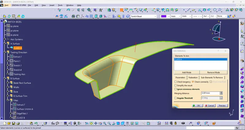
Figure1: Join Operation for checking connectivity.
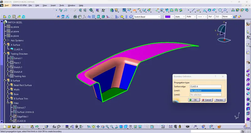
Figure2: Boundary Operation for checking connectivity.
- Step 2: Determine Tooling Axis:
- Extract the base surface of the Switch Bezel and place a point in between the Surface > Point definition select surface > Distance = 0mm and place an Axis system on that point.
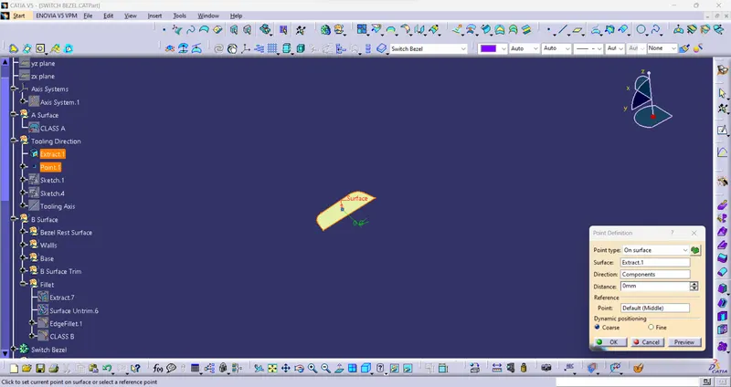
Figure3: Creating a point on the Base Surface.
- Now using the axis system and the point create a sketch for the tooling axis along the Y direction.
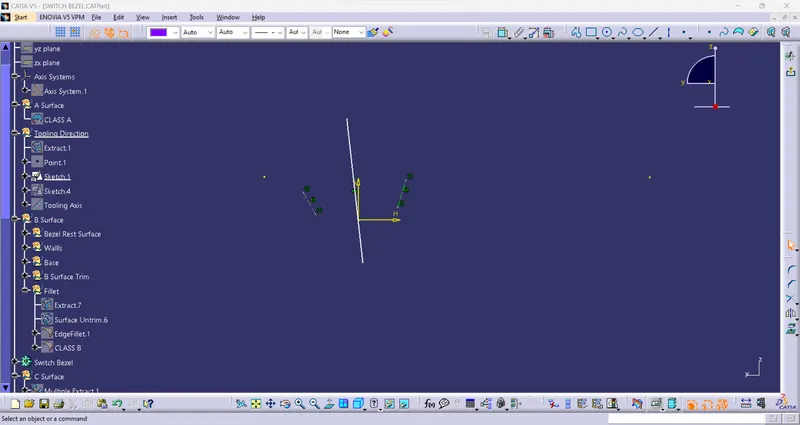
Figure4: Tooling Axis in the Y-direction.
- Using the same method we will also create the tooling for X direction.
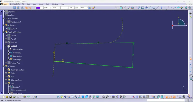
Figure5: Tooling Axis in the X-direction.
- Now that we have achieved the tooling axis for the X and Y directions we will use these two tooling axis to create the main Tooling Axis i.e. along the Z direction by bisecting the X and Y direction lines.
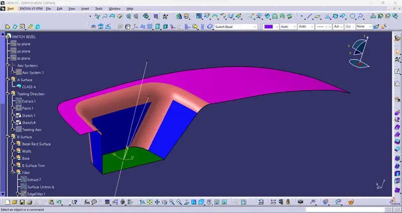
Figure6: The X and Y Tooling Axis.
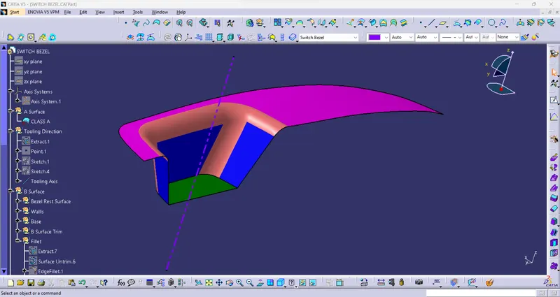
Figure7: The required Tooling Axis for the Switch Bezel.
- We have the Tooling Axis now so let's publish the Tooling Axis and the Class A Surface of the Switch Bezel.
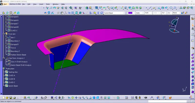
Figure8: Publication of the Tooling Axis and the Switch Bezel.
- Step 3: Draft Analysis of Class A Surface:
- Change View Mode Customization to the Material mode for the Draft Analysis.
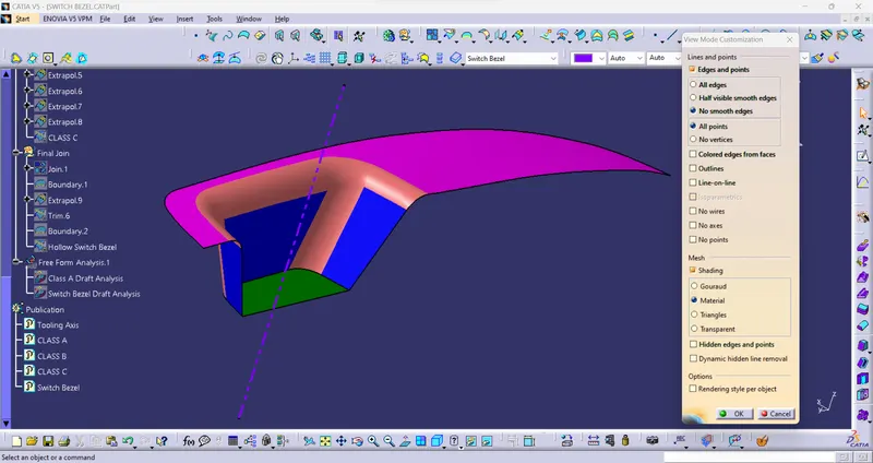
Figure9: Material Mode.
- Go to INSERT > ANALYSIS > FEATURE DRAFT ANALYSIS and move the compass to the Tooling Axis. Change the range to 3°. Apply the settings as shown in Figure 10.
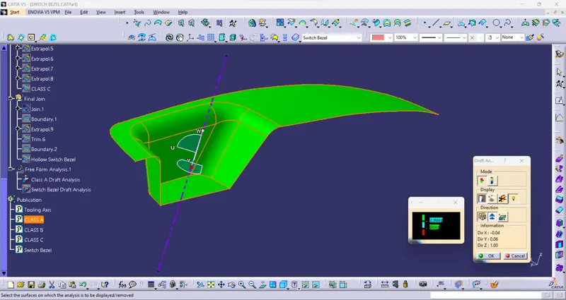
Figure10: Draft Analysis tools Switch Bezel.
- The Draft Analysis of the Class A Surface of the Switch Bezel is shown below the Component is safe.
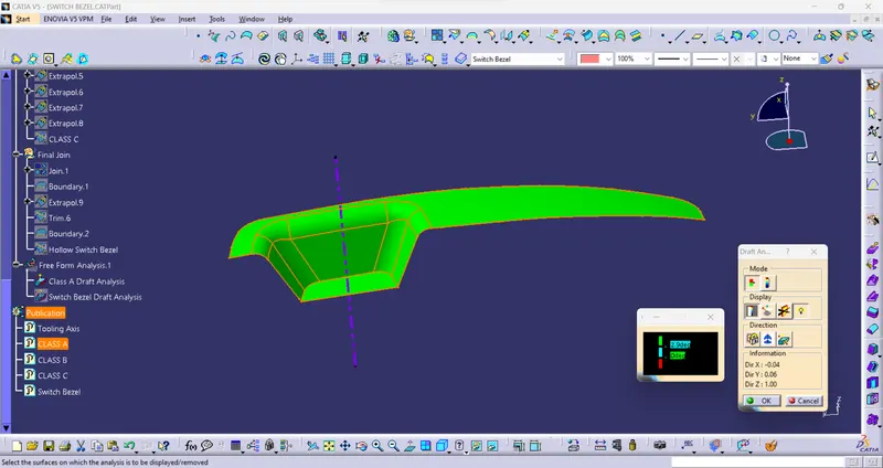
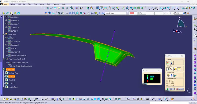
Figure11: Screenshot of Draft Analysis of Class A Surface of the Switch Bezel.
- Step 4: Class B Surface:
Now we need to create a B Surface which will be similar to the A surface at an offset value of 2.5mm.
- First, we will start by creating the Bezel Rest Surface for this we will Extract the upper part of the Switch Bezel, Untrim it and Offset it to a distance of 2.5mm.
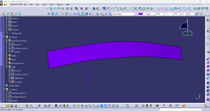
Figure12: Final look of the Bezel Rest Surface after the above operations.
- Now let's make the Walls we require, let's Extract the 3 walls that we require from the Class A surface Untrim them, Extrapolate them, Trim all 3 walls together and at last Offset them at a distance of 2.5mm.
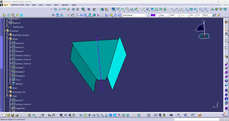
Figure13: Final look of the 3 Walls after the above operations.
- Now let's make the Base we require, let's Extract the base of the Class A surface Untrim them, Extrapolate and at last Offset them at a distance of 2.5mm.
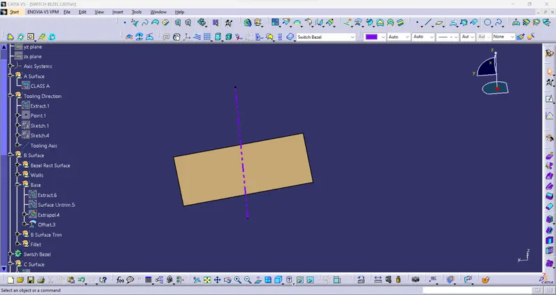
Figure14: Final look of the Base after the above operations.
- Now that we have created the required surfaces for the B Surface, let's Trim them together and get a final output of the B Surface. First, let's trim the Bezel Rest Surface and the 3 Side Walls.
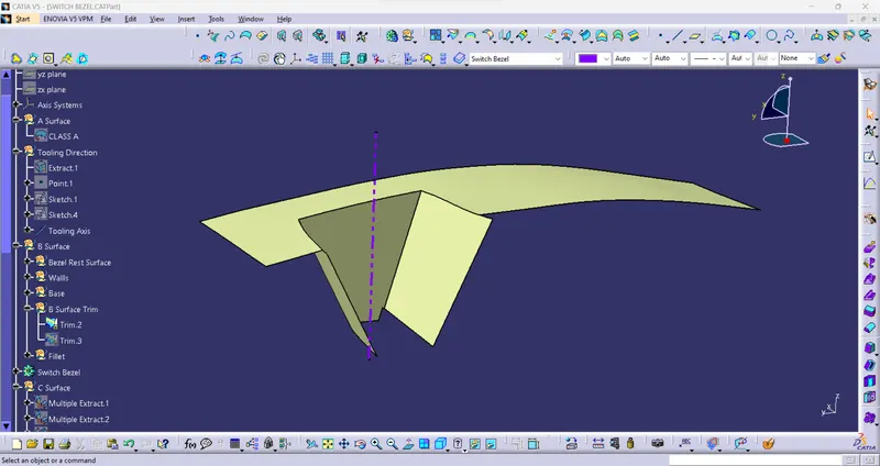
Figure15: Final look after the trim of Bezel Rest Surface with 3 Side Walls.
- Let's use the above trim and Trim it with the Base Surface that we have created for the final output of the B Surface of the Bezel Switch.
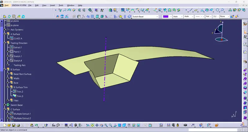
Figure16: Final look after the trim of Bezel Rest Surface, 3 Side Walls and Base.
- To complete the B Surface, we have to apply the Fillets to the above Surface obtained after trim.
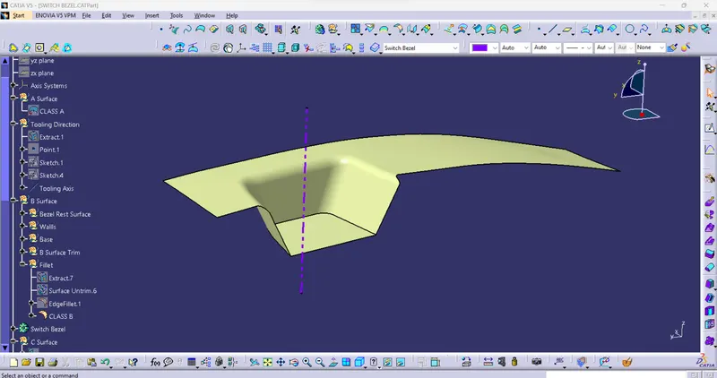
Figure17: The Final Trim output of the Class B Surface with respective Fillet values.
- Step 5: Class C Surface:
- To create a Class C Surface, first, Multiple Extract the boundaries of the Class A Surface.
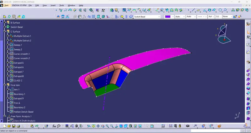
Figure18: The Outside Boundary of the Class A Surface created by Multiple Extract.
- Now we will create a Smooth Curve operation on the Extracted Boundaries of the Class A Surface so that when we create the Sweep operation the Surface will be smooth and will not have patches.
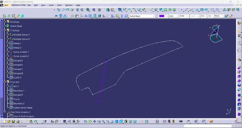
Figure19: Smooth Curve Operation on the Outside Boundary of the Class A Surface created by Multiple Extract.
- Now we will use the Sweep option to create the required surface. To perform this operation, Go to the Toolbar > Sweep > Profile type > Line > Subtype: With draft direction > Guide curve 1- (select the extracted boundaries) the in Draft direction (select the tooling axis) angle and length as 3° and 20mm respectively and click ok.
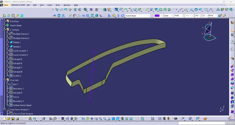
Figure20: Sweep operation output on the boundary surface of Class A Surface.
- We will also Extrapolate this Surface we got so that it is a closed surface and also use the Trim so that the surfaces are properly joined.
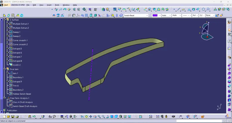
Figure21:Final Class C Surface after the Extrapolate and Trim operations.
- Step 6: Creation of Final Switch Bezel Surface and Close Surface Body:
- After the creation of Class A, Class B and Class C Surfaces, we need to join Class A and Class C surface to form a new surface. Then trim the joined surface with Class B surface to form the Final Switch Bezel Surface.
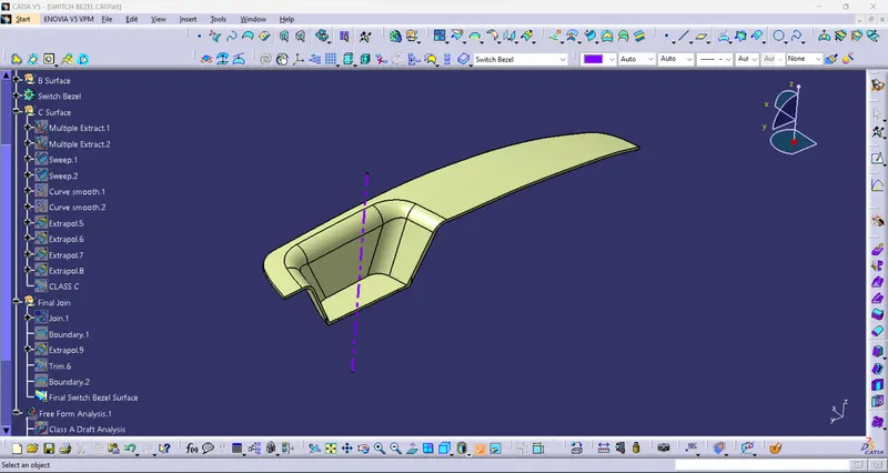
Figure22: The Final Switch Bezel Surface after the above operations.
- Now that we have the required surface we can make a Solid Body out of it. To make a solid body we will go to the Part Design section over there we will use the Close Surface tool to make a Solid Body.
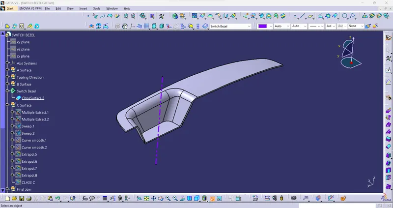
Figure23: The Solid Body made with the Close Surface operation inside Part Design.
- Step 7: Draft Analysis of the Switch Bezel Body:
- Change View Mode Customization to the Material mode for the Draft Analysis.
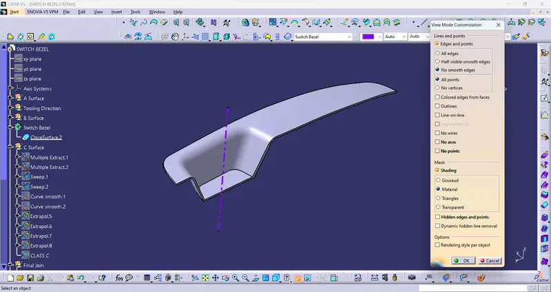
Figure24: Material Mode.
- Go to INSERT > ANALYSIS > FEATURE DRAFT ANALYSIS and move the compass to the Tooling Axis. Change the range to 3°. Apply the settings as shown in Figure 26.
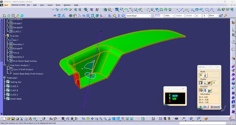
Figure25: Draft Analysis tools Switch Bezel Body.
- The Draft Analysis of the Switch Bezel Body is shown below the Component is safe.
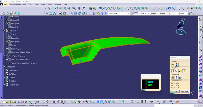
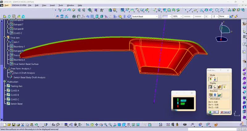
Figure26: Screenshot of Draft Analysis of the Switch Bezel Body.
- Terms asked to Mention:
- Tree Structure:
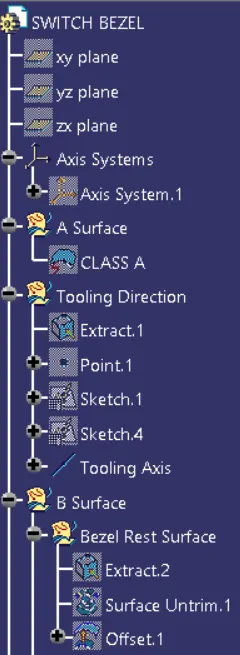
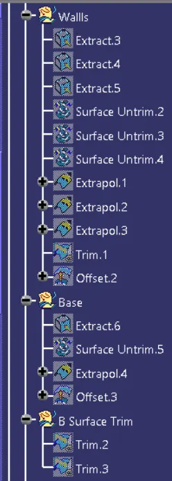
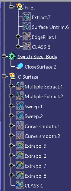
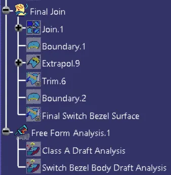
Figure27: Screenshots of Tree Structure of Switch Bezel.
- Publications:
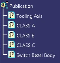
Figure28: Screenshot of Publications made.
- Screenshots of the model with the proper colour code of the draft angle in various orientations (Isometric, Front, Side, and Top View):
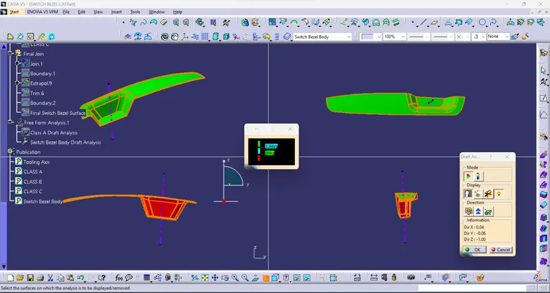
Figure29: Model in Various Views.
RESULT:
- The Draft Analysis of the Class A Surface of the Switch Bezel is shown below the Component is safe.
Figure30: Result of Draft Analysis of Class A Surface of the Switch Bezel.
- The Creation of the Class B Surface.
Figure31: Final Result of the Class B Surface.
- The Creation of the Class C Surface.
Figure32: Final Result of the Class C Surface.
- Creation of Final Switch Bezel Surface and Close Surface Body.
Figure33: Final Result of the Switch Bezel Surface.
Figure34: Final Result of the Switch Bezel Body made by Close Surface.
- The Switch Bezel Body has passed the Draft analysis test as the draft values of the Switch Bezel are less than 3° and the Bezel is safe for production.
Figure35: Result of Draft Analysis of Switch Bezel Body.
CONCLUSION:
1. Class A, Class B and Class C surfaces are created following standards of the automotive industry using Catia V5 software.
2. Draft Analysis was performed on the Switch Bezel and it was observed that the draft was under the permissible limit for the manufacturing of the component using the injection moulding process.