Week 8 - Challenge 5 - Core & Cavity Design
AIM:
To create the core and cavity blocks for the switch bezel with the parting surface and parting line.
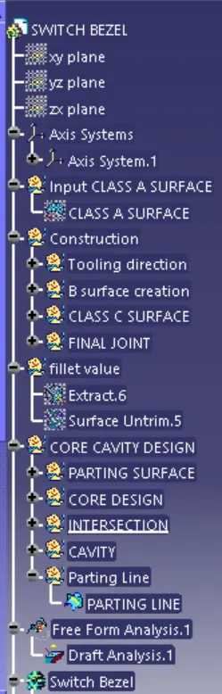
CORE AND CAVITY DESIGN:
The core is the part that forms the internal shape of the molding. The cavity is the part that forms the external shape of the molding. The core is the side of the tool where the plastic part is injected also known as the bottom half of the tool. A tool with impression is called a cavity mold.
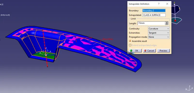
Extract the boundary of Class-A and extrapolation the boundary of class-A by 15mm.
unhide the class C surface and trim with Class-A
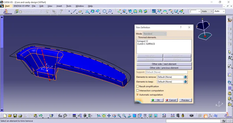
Trim the result with class-B to form a Parting surface
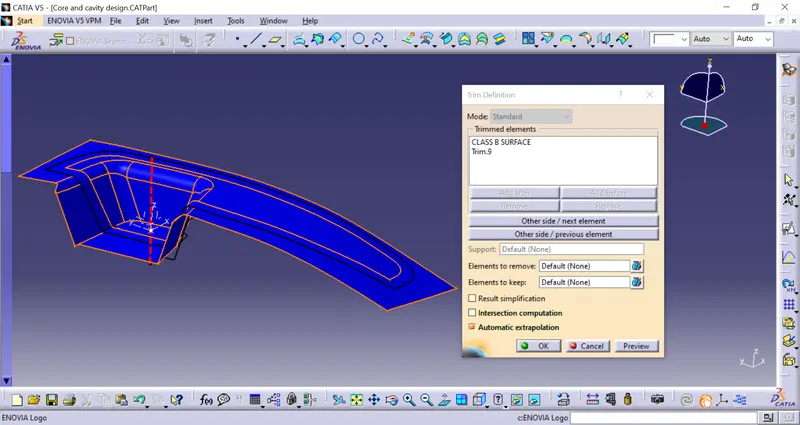
CORE DESIGN:
Unhide the axis system to ensure it is in the part.
Draw a rectangle of the core block around the component to ensure it covers all the component blocks.
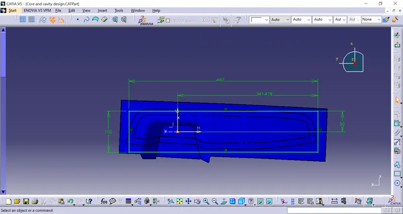
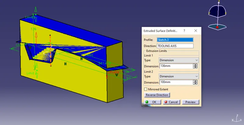
Extrude the rectangle around the part towards the cavity and core side through the tooling axis.
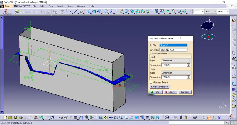
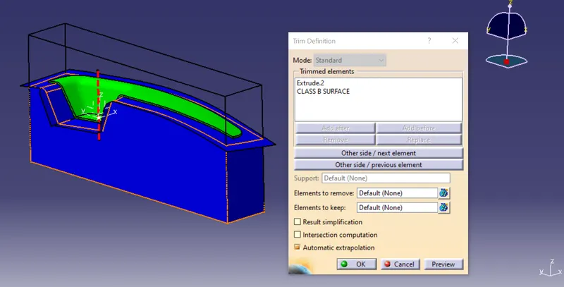
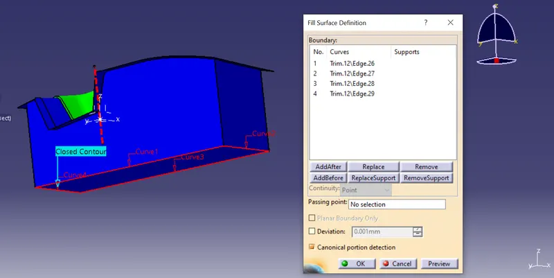
trim the extrude with a parting surface and fill the top of the extrude in the core block.
join the fill with extrude.
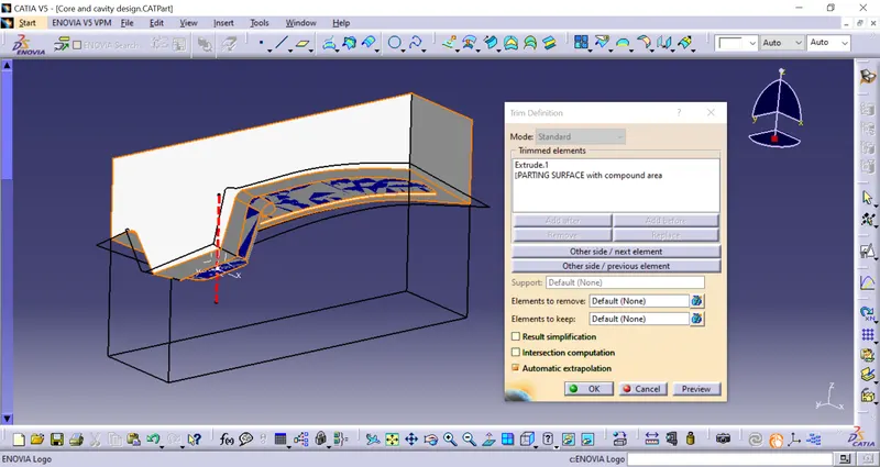
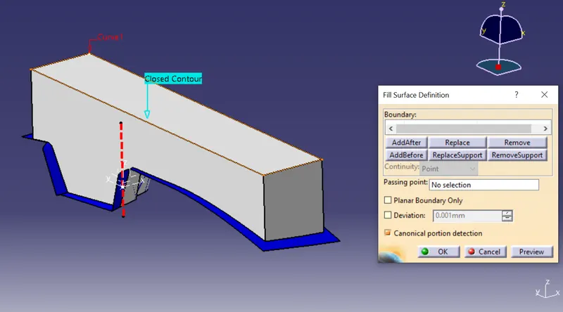
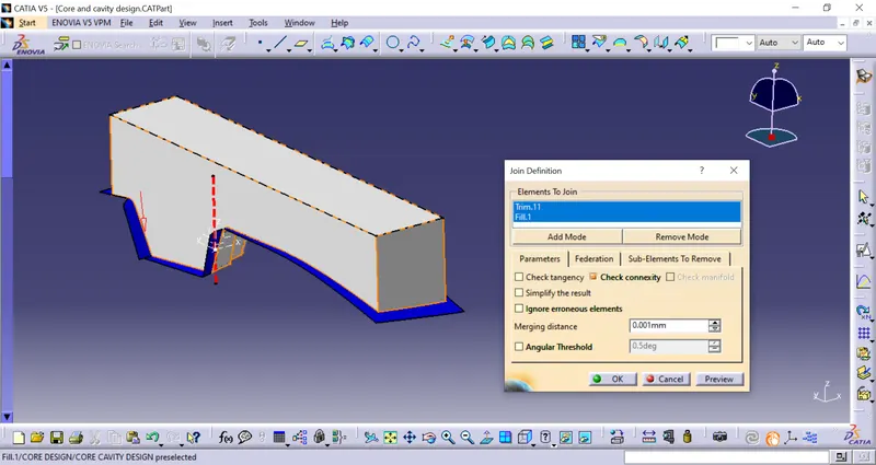
now the intersection of the core block and component is shown as intersection line as below.
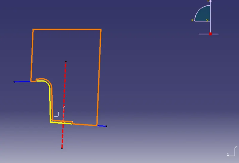
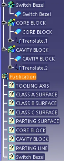
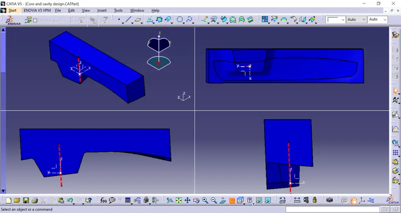
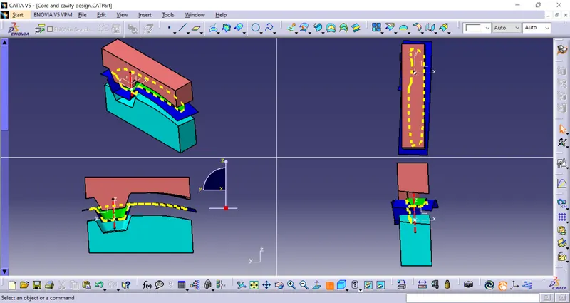
various orientations of Core block (Isometric, Front, Side, and Top View)
CAVITY BLOCK:
Extrude the rectangle through the cavity side and trim the extrude with a parting line and fill the bottom surface of the cavity block and form a solid using part workbench.
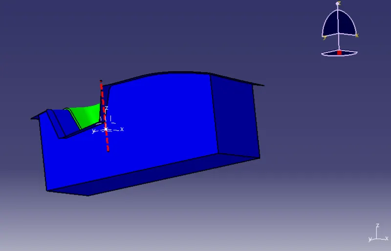
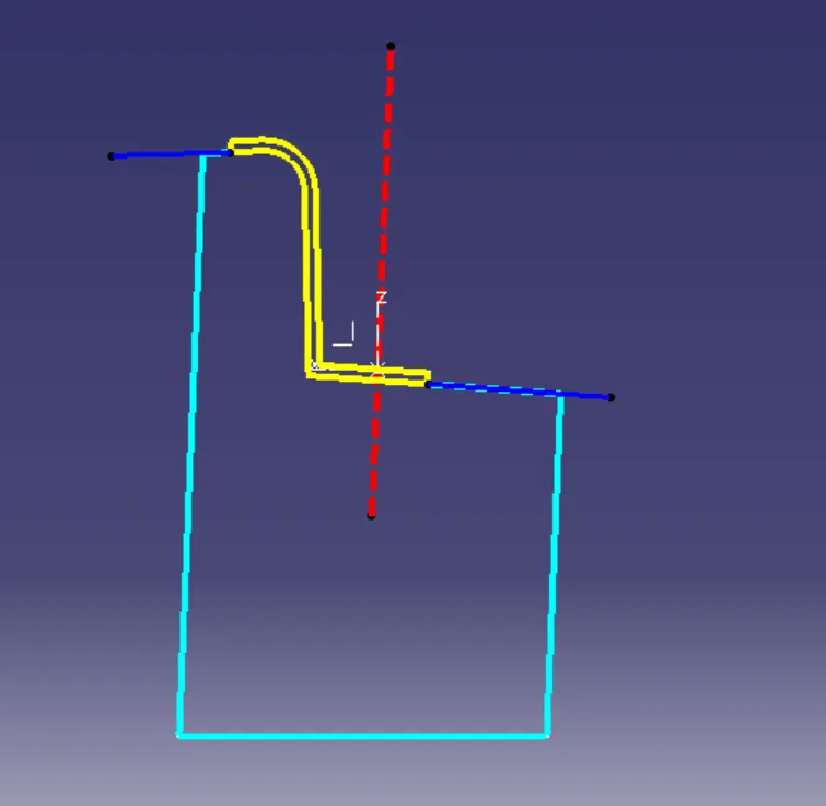
intersection line for the cavity block and the parting surface with the component.
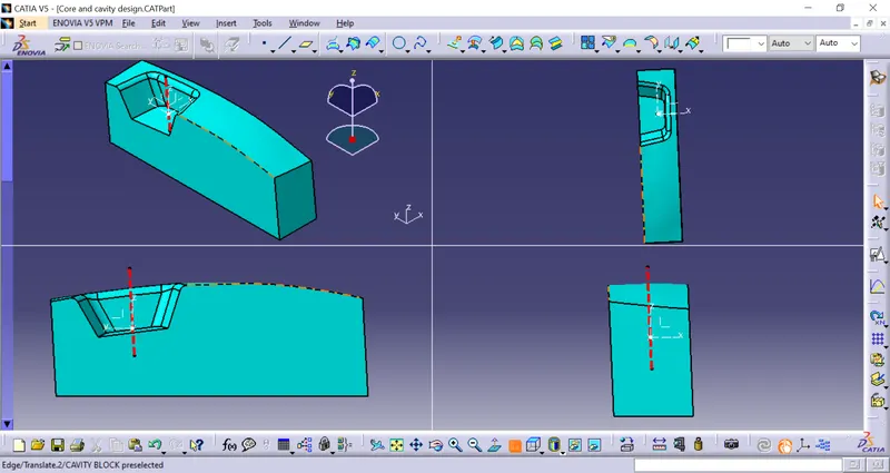
various orientations of cavity block (Isometric, Front, Side, and Top View)
PARTING LINE AND PARTING SURFACE:
The parting surface is just a big projection of the plastic component, the core and cavity should be tightly sealed to avoid metal flow leakage where the parting surface role comes. the parting surface should be on the B surface and ensure is not on the A surface.
The parting line is one which is the junction of core and cavity and the parting surface is a replica of a plastic component boundary.
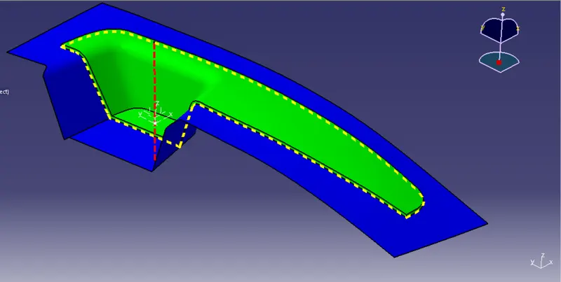
the intersection of the core and cavity as shown below
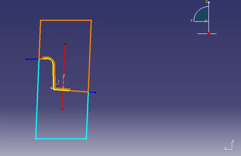
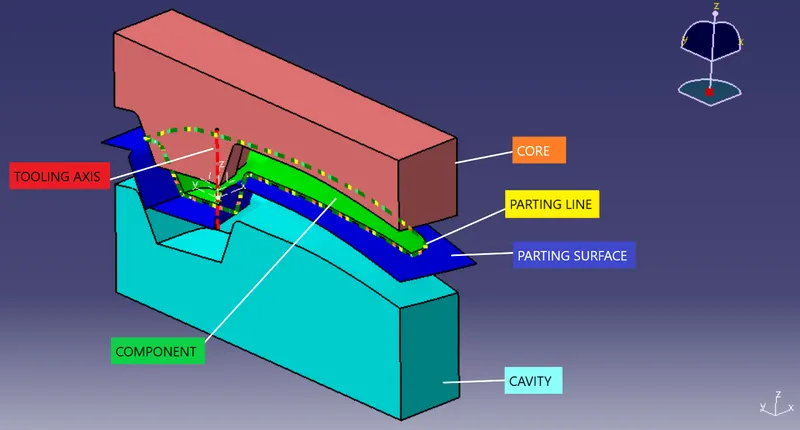
various orientations of Core and Cavity block (Isometric, Front, Side, and Top View)
Drafting analysis on the solid part body:
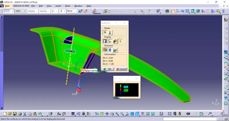
- After creating the solid body we will perform the draft analysis of the whole part body.
- First, change the parameter to material mode and then go to perform draft analysis Go to Insert > analysis > feature draft analysis.
- Click on the compass icon & align with the tooling axis.
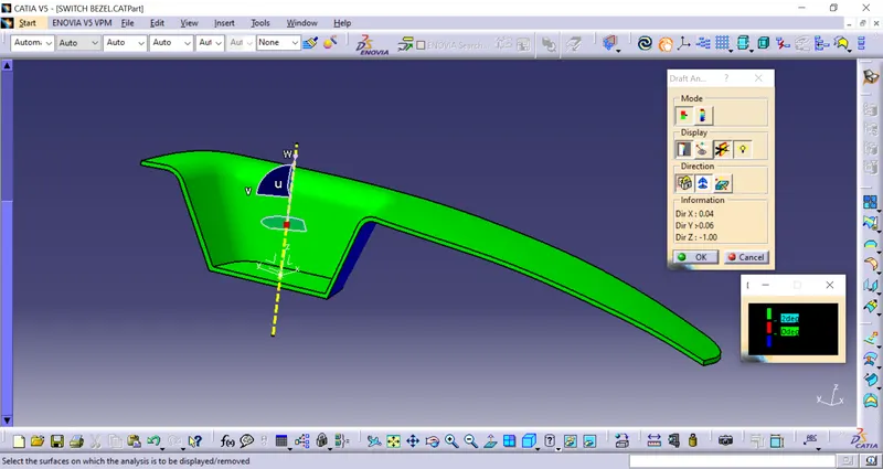
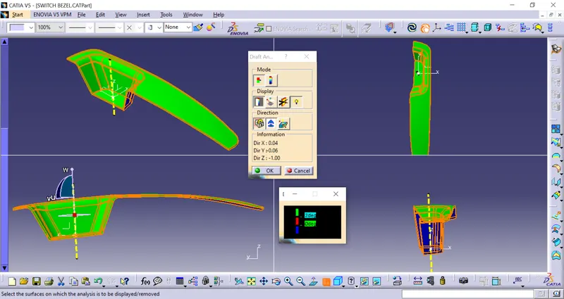
- The below image is analyzed under the running point to see the angle of the surface.