Week 8 - Challenge 3 - Coin Holder Design
Objective :
Create the Coin Holder Plastic component through the given Class-A surface. To begin with, the tooling axis for the given Class-A Surface should be created meeting the requirements of the draft angle and at the end perform the Draft analysis on the model.
Design Methodology with images:
1. Rename the Geometrical set as Class- A and Publish the input Class A Surface.
2. Then We have to make tooling axis to analyse the direction of tooling where all the required surfaces will clear smoothly.
Procedure for creating Tooling Axis:
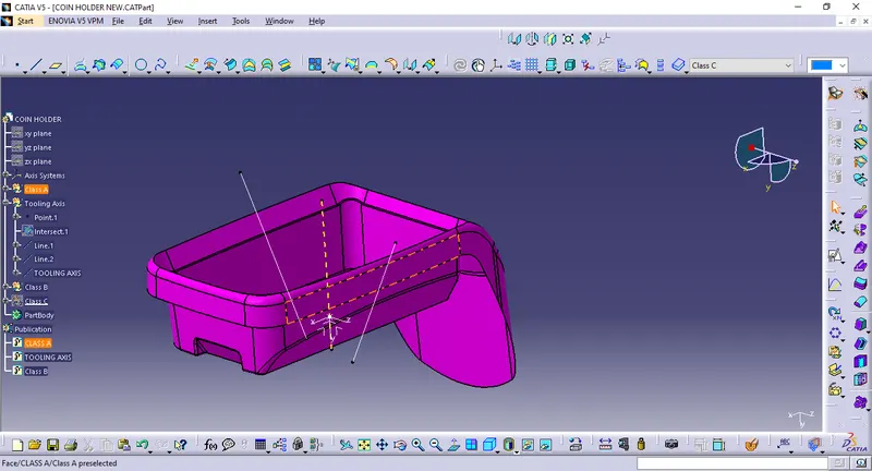
- A Reference Point is created along the required Surface and a new Axis system is created
- Then Direction needed to check for tooling where all the surfaces should be clearing.
- Here, intersect is taken with Y-Z plane along the Class A surface.
- Intersect made will help to ge reference lines bisecting which we can get the required tooling axis.
- Finally the Tooling axis is created by bisecting the two lines and it is published.
- The tooling Axis determines the direction of Class C boundary swept with draft direction.
- When viewing from tooling direction normal all the parts that are drafted should be visible so it gives an idea to determine product manufacturing in Injection molding.
Procedure for Draft Analysis:
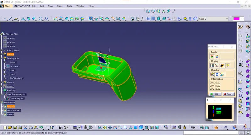
- The part created has to be changed to material mode in display frame
- Then by enabling compass definition the axis system is pan along the direction of the part and aligned in line with the tooling direction
- Lock Direction is applied that fixes the compass and then the mode dialog box is formed by snapping at any point on the part
- The Color Codes are classified and Draft Angle are applied
- Then the Running point analysis is used to hover around the part to analyze the permissible draft angles and the analysis is saved
Procedure for B Surface Creation:
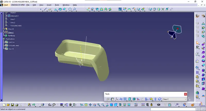
- The next step is to design B surface for the input which is usually the surface where all engineering aspects and support creations are done.
- The B surface Creation is performed using surface operations in CATIA which is an offset from Class A with dimension proportional to the thickness of the part
- In Coin Holder Design the B surface is offset 2.5mm from the input Class A Surface which is the thickness of the part
- The B surface is an extrapolated surface compared to A surface and forms the bottom skin of the part.
Procedure for C Surface Creation:
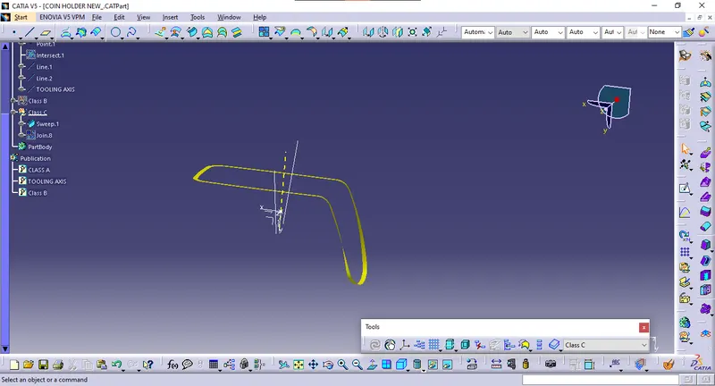
- The Next step is to from the C surface which is an intermediate surface between A and B and is used to give the closed surface appearance to the design
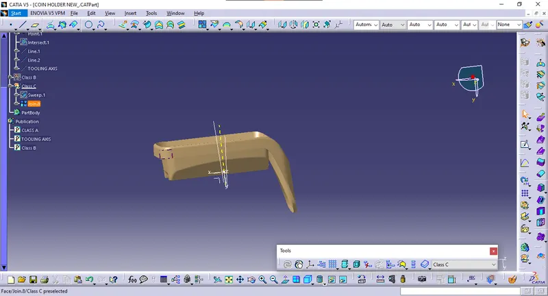
- The C Surface is swept using the profile as boundary line of Class A which is the Guide curve with a subtype along draft direction.
- The Direction of the sweep is the tooling direction formed earlier
- The draft angle for the sweep operation is provided which is 3 degrees and surface is swept for length above the thickness of the specified part
- The C surface is refined using smooth Curve options to remove the complexity and patches along the swept surface
- Finally the Class A and Class C surfaces are joined together and connexity of surfaces should be less than 0.003mm and the surfaces are merged.
Procedure for Closed Body Creation
- The merged surface is then trimmed with B surface to form the closed surface.
- The Closed surface is then validated to find the irregularities along the edges and imperfections along the edges were then corrected using operation like extrapolate and surface trim
- This Closed surface is the outer skin of the Coin Holder and finally the part is formed by Closed Surface in part design workbench
- The final part is measured to validate the uniform thickness of the part especially along the filleted edges.