Wiring harness routing & packaging Rules Week 3 Challenge
Report on defining the Electrical Clip, Electrical backshell and Corrugated Tubes
- P-Clamp:
1. Download the P-Clamp 3D file from the given above link
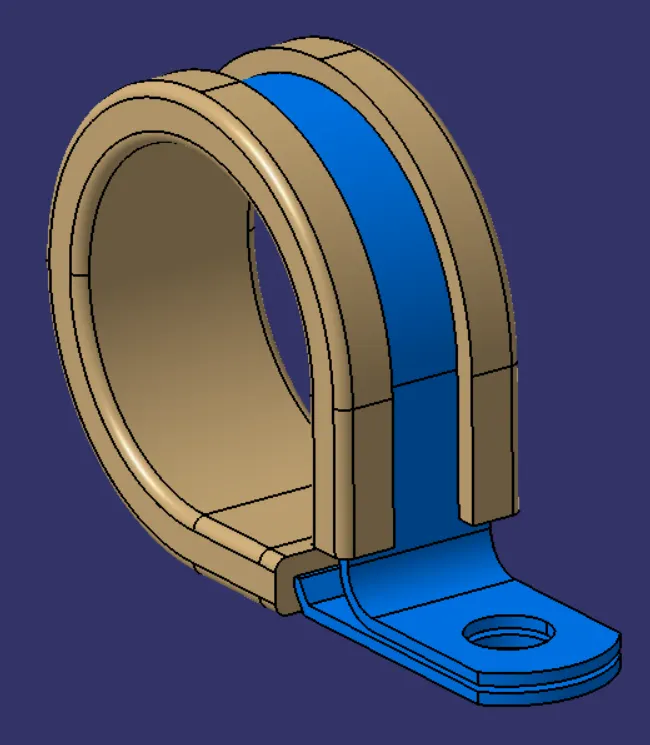
Figure: P-Clamp
2. Define the geometrical parameters of the P-Clamp by creating the Entry point & plane, Exit point & plane and Base plane.
3. We create two points as the entry point and the exit point opposite to each other.
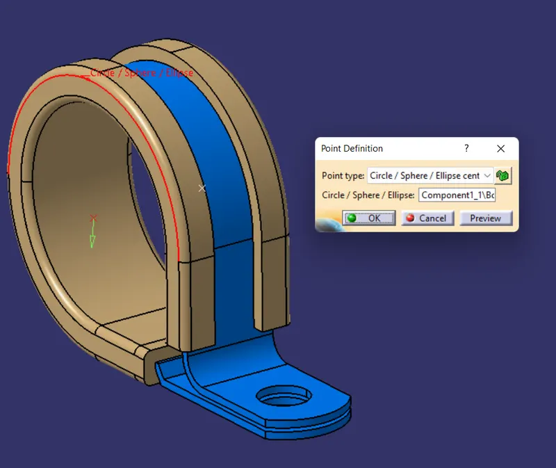
Figure: Entry point
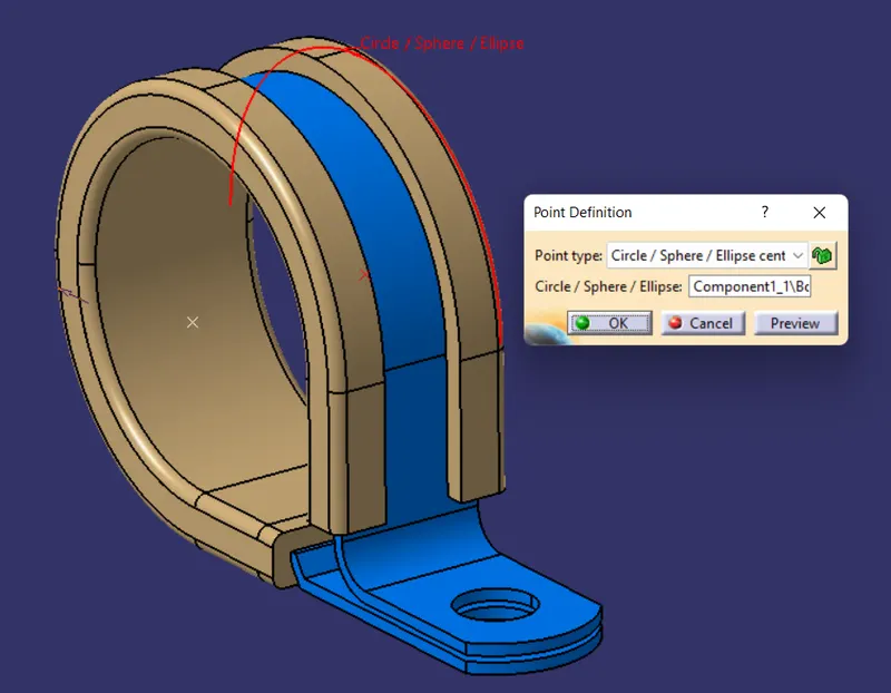
Figure: Exit point
4. Next, create entry plane with reference to entry point and exit plane with reference to the exit point also create a base plane at an offset of 2mm from the base surface.
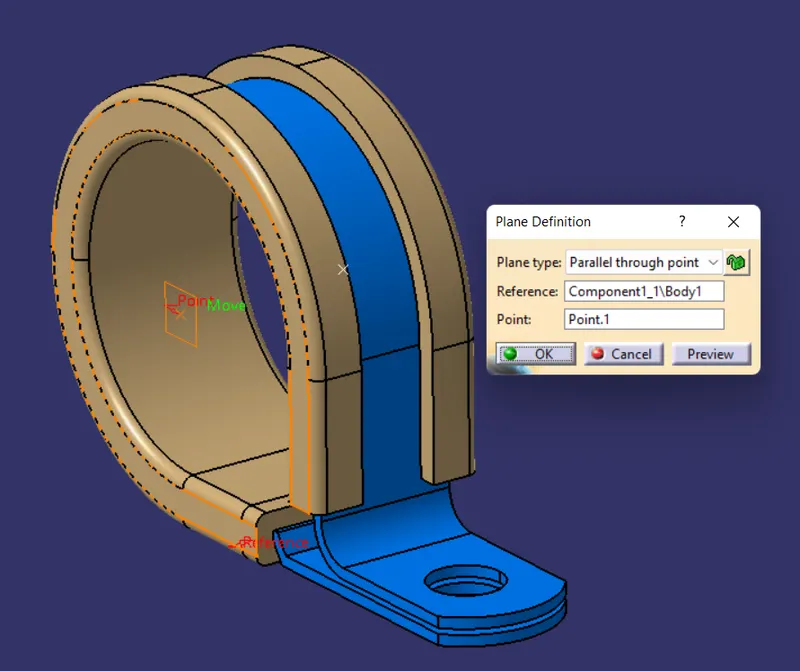
Figure: Entry plane
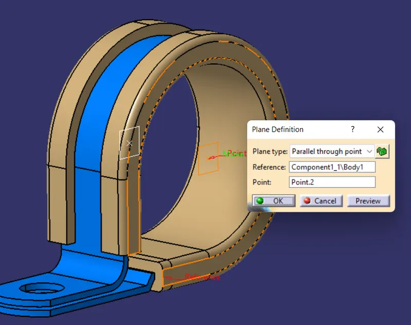
Figure: Exit plane
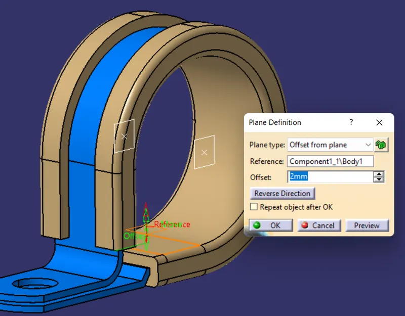
Figure: Base Plane
5. Switch to the "Electrical Part design" workbench and Using the "Support Definition" command select the part and the entry point,plane and the exit point, plane with base plane we created.
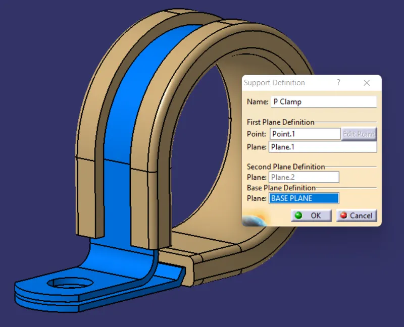
Figure: Support Definition
6. Using the "Support Definition" command again select the part and select the point opposite to the previous selected point and select the entry plane with the base plane and the secondary plane gets selected automatically as the Clip has two entry points and two exit points.
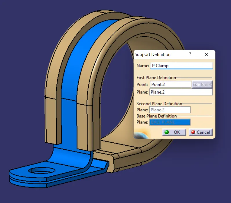
Figure: Support Definition
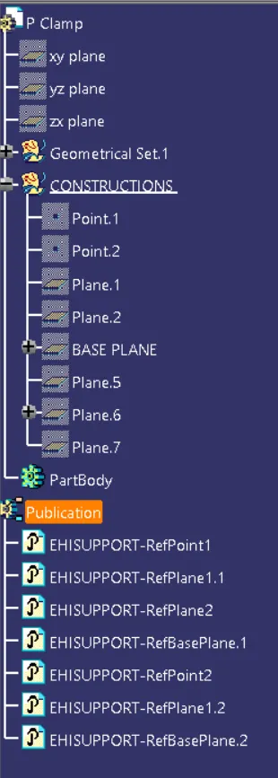
Figure: Expanded Tree
7. Save the part file in the catalog document created using the " Store Device" command.
- Tyco-1738312:
1. Download the Bach shell 3D file from the given link above and define the geometrical parameters by defining the backshell connection point and the bundle connection point.
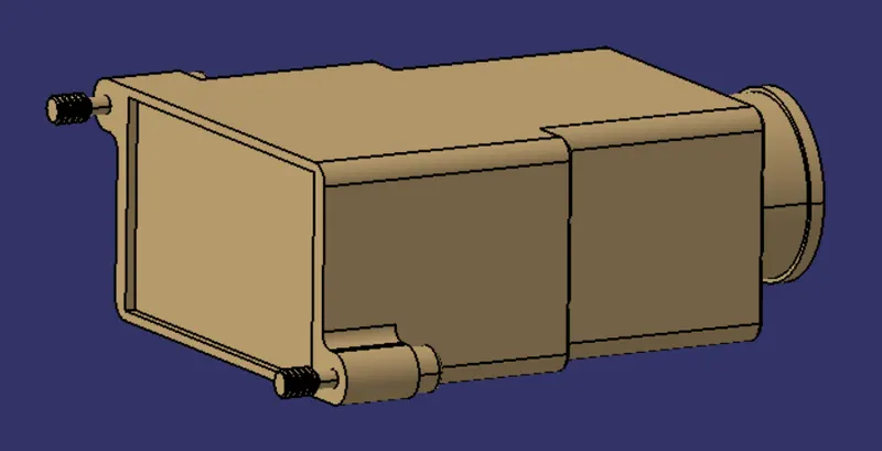
Figure: Bachshell
2. Create the backshell connection point on the normal to the mating surface
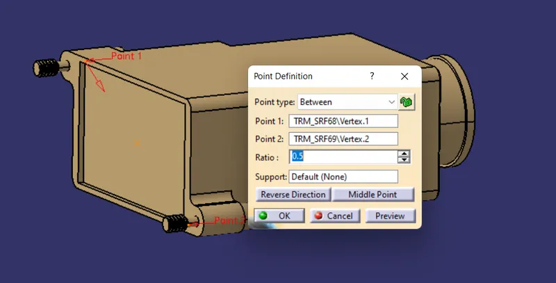
Figure: Backshell connection point
3. Create backshell axis system with backshell connection point as the reference and axis created such that the Y-axis should be pointing towards the front face of the backshell and the X-axis should be pointing towards the locking mechanism and the Z-axis should be pointing across left to right.
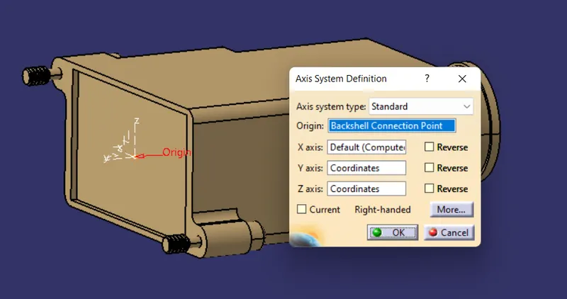
Figure: Backshell axis system
4. Create the Bundle Connection point on the opposite face.
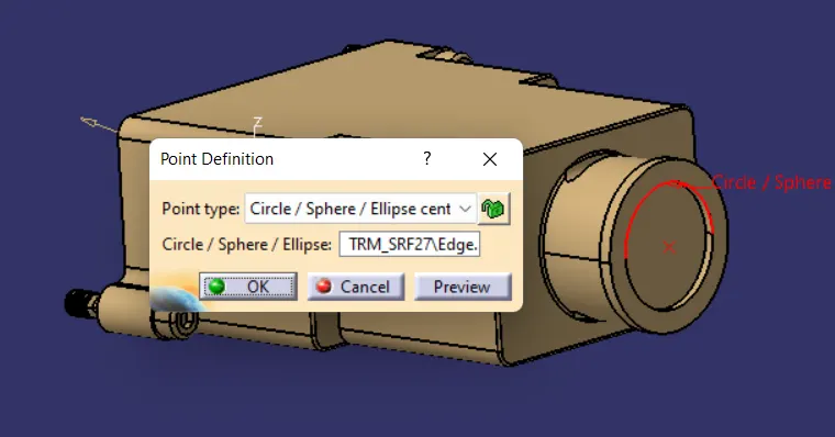
Figure: Bundle Connection point
5. Next, Switch to "Electrical Workbench" and define the part electrically using the "Define Backshell" command.
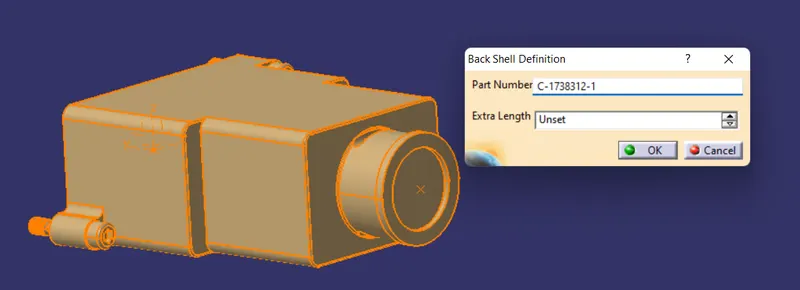
Figure: Define Backshell command
6. Using the " Define Backshell Connection point " command define the backshell connection point by selecting the appropraite point and face with considering the Y-axis as the coinsidence and the X-axis as the orientation
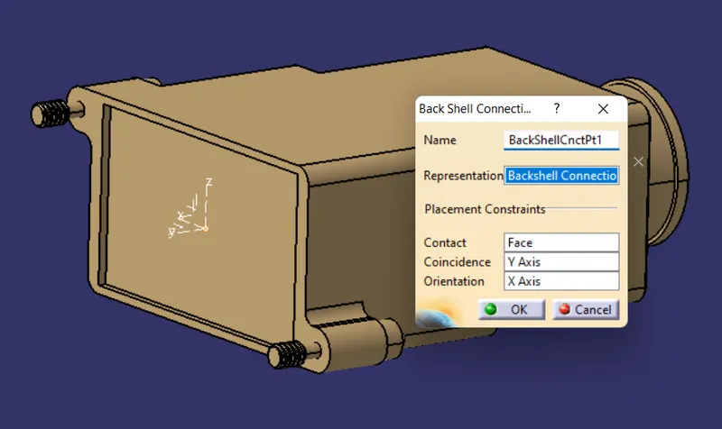
Figure: Backshell connection point command
7. Using the " Define Bundle connection point " command define the bundle connection point by selecting the appropriate face and point.

Figure: Bundle Connection point commnad
8. Using the " Store Device " command save the file in the catalog document created.
- Corrugated Tubes
1. Begin the Electrical Part design workbench and select "Define Protection Part" command to create the corrugated tubes.
2. Click on the Part in specification tree and provide the given parameters with bend as "1.5 * Outer diameter".
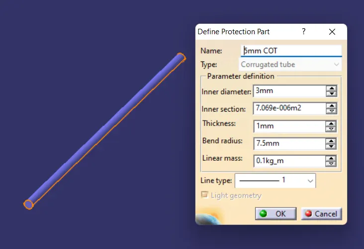
Figure: 5mm corrugated tube
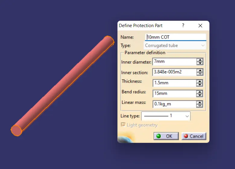
Figure: 10mm corrugated Tube
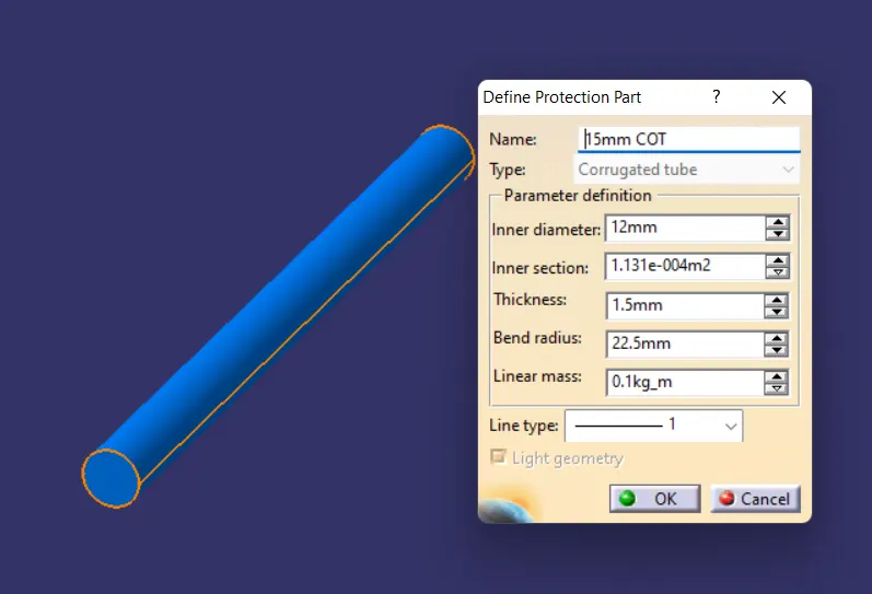
Figure: 15mm Corrugated tube
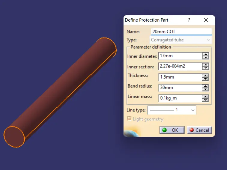
Figure: 20mm corrugated Tube
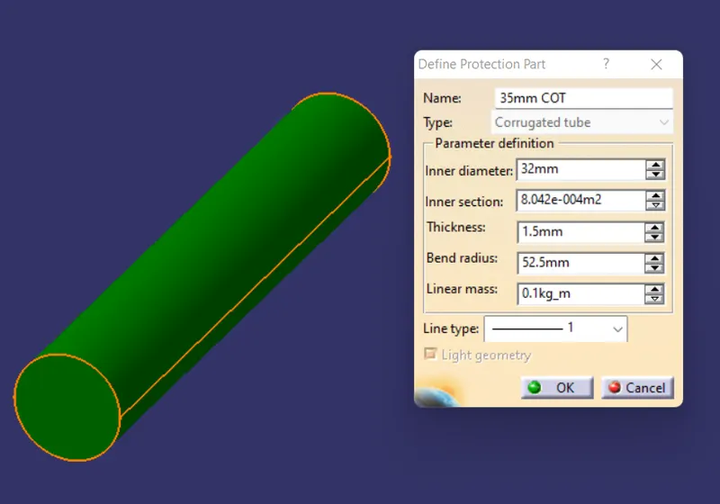
Figure: 35mm corrugated tube
3. Next, create a catalog document by new catalog document option and new family in it and name it as "Slit COT " and change the type to conduit and save the catalog document.
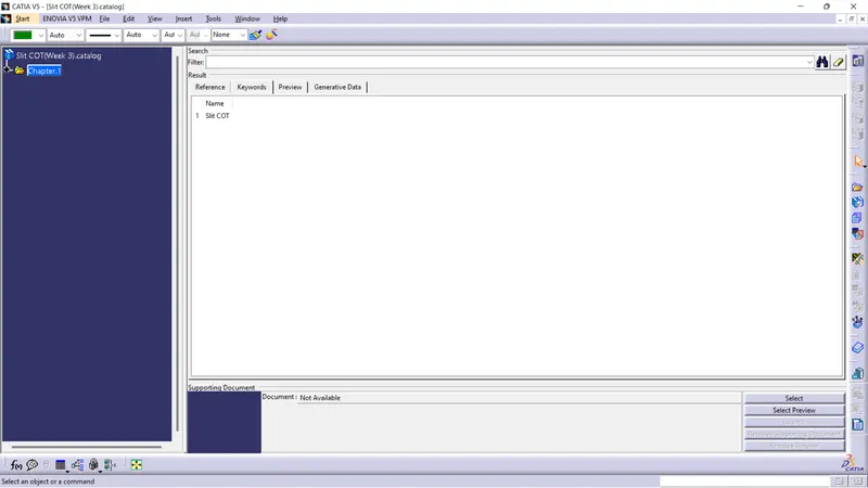
Figure: Catalog Document
4. Finally, save all the corrugated tubes file in the " Slit COT" catalog document.
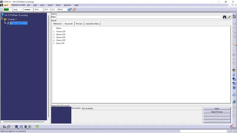
Figure: Files saved in catalog document