Week 8 - Challenge 3 - Coin Holder Design
Design of COIN HOLDER with the help of CATIA V5
*Objective:
To design a coin holder with respect to the class a surface
Create class b surface and class c surface and the tooling
Convert those kids' surfaces into a close body and make them into the solid body providing the thickness of 2.5 mm
Performing draft analysis to verify the creation of tooling axis and class C surface.
THE GIVEN CLASS A SURFACE.....
*Here we are using the software CATIA v5 generative safe design
*How to create class B surface….
. Many surfaces we have to extract from the class a surface and have to trim that surfaces for -creating the class B surfaces
-The surfaces are the side wall top wall base outer wall.
-Extract the side wall with no propagation in the exact option
-Untrim them.
-Extrapolate the walls with a point continuity of distance of 20 mm.
-Trim the walls to get the required shape.
-Offset those walls with a thickness value of 2.5 mm.
-Extract the surfaces separately and untrim them.
-Extrapolate that surfaces with a required distance of 20 mm offset them with the thickness value of 2.5.
-Trim them for the required shape.
-Measure the fillets value from the class a surface calculate it and give some distance if the fillet value is 10 then and you have given the offset value 2.5 at the class B surface then you have to add that offset will you because the curvature is increased due to the surfaces are going outside so the fillet value is 10 + 2.5 mm.
-You can follow the same process for creating the outer wall.
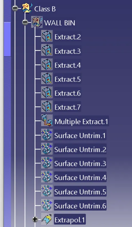
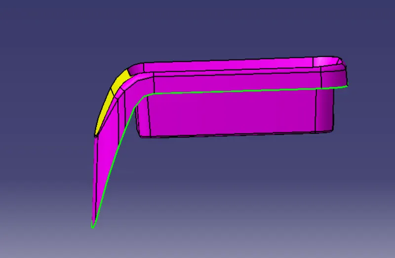
WALL BIN:-
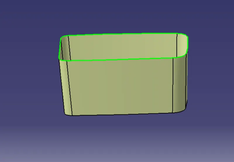
TOP WALL:-
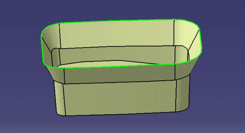
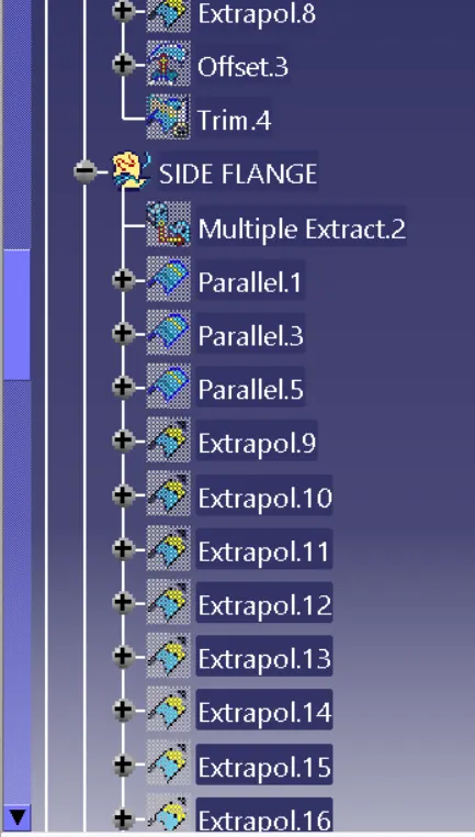
SIDE FLANGE:-
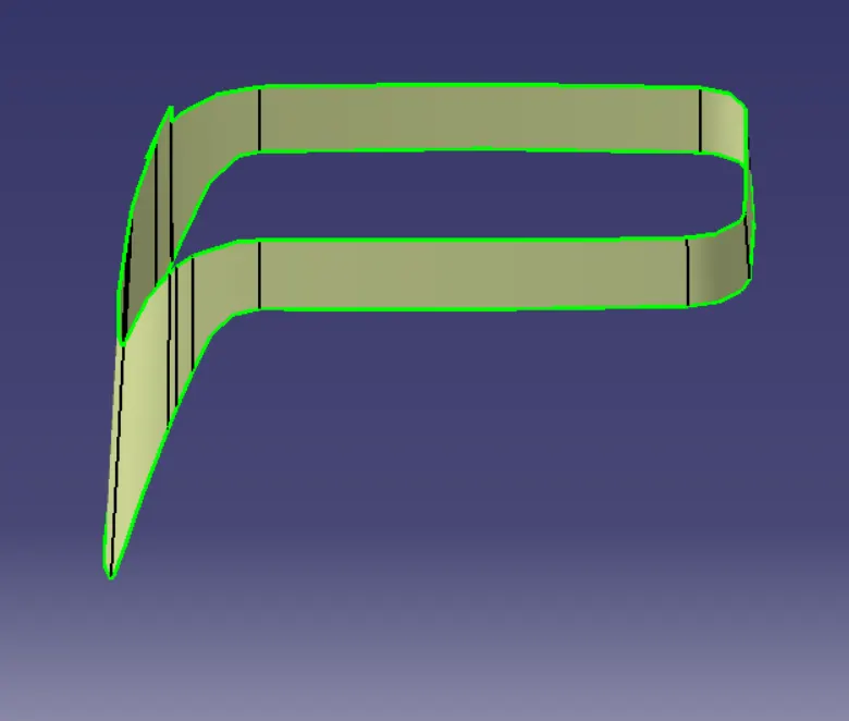
SIDE FLANGE UPPER PART:-
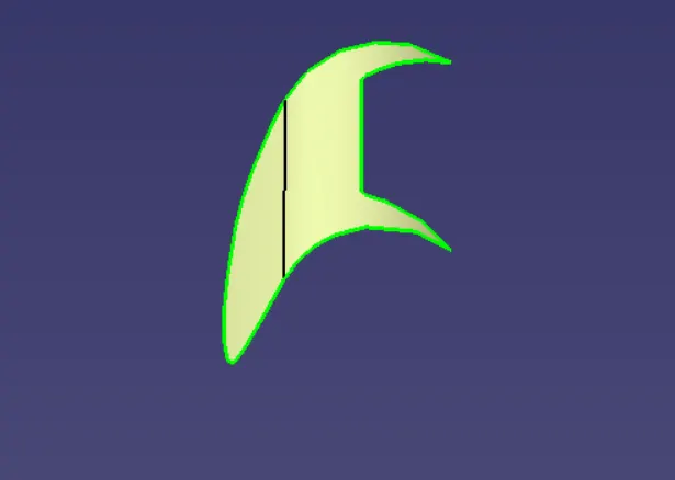
JOINING OF CLASS B:
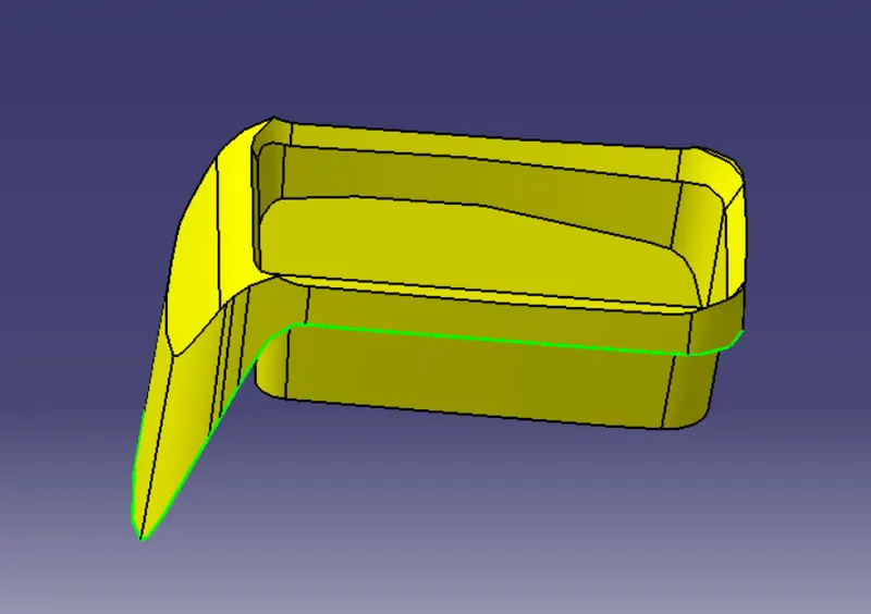
*How to create class C surface…..
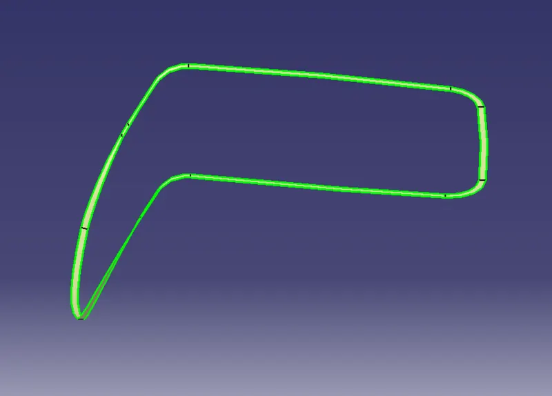
-First, get the boundary lines of class surface separately.
-Smooth curve with smooth option as boundary line has a lot of vertices.
-Swift curve with tooling Axis as a direction in the Swept option you can take the direction with surfaces first select the boundary and then select the surface of class A as reference surfaces.
-Now trim that surface with class B surface.
CLASS C SURFACE:
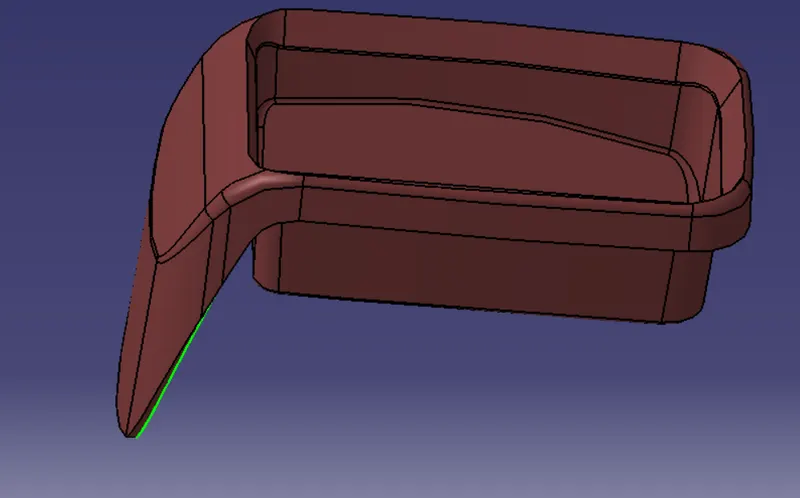
JOINING OF CLASS A, B ,C SURFACE:
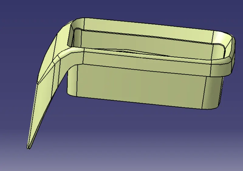
* How to create a closed body…. AND APPLYING DRAFT ANALYSIS:
- Join the class a surface class b surface and classy surface joint surfaces with the class be
-Go to the part design and insert a body to create a closed surface
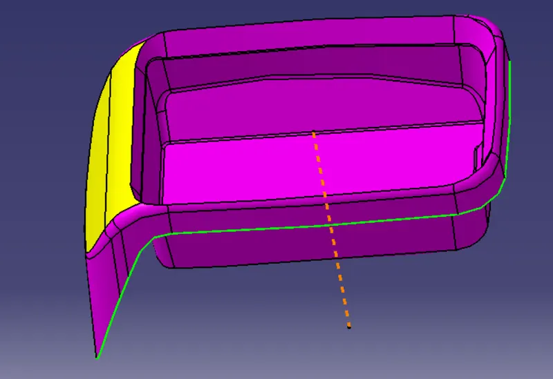
-Procedure of creating draft analysis
-Go to insert menu and select the analysis option
-Select feature and draft analysis
-Select the material option and select the surface
-Drag the compass and place on the tooling axis
make sure that the top surface is in green colour as draft angles should not exceed 3 degrees.
-Click on okay after confirming the model.
SOLID-BODY
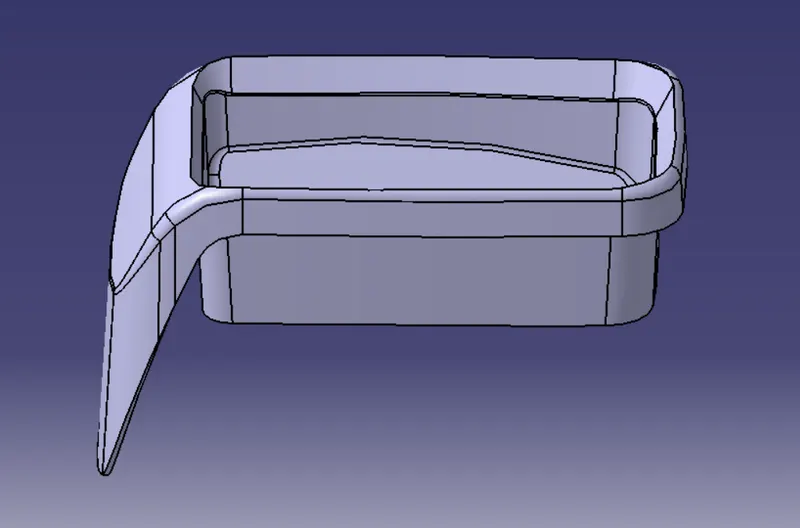
TOOLING AXIS:
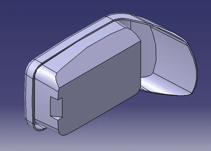
ISO VIEW
FRONT VIEW
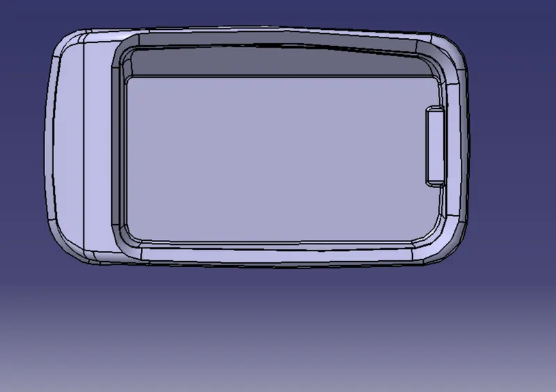
TOP VIEW
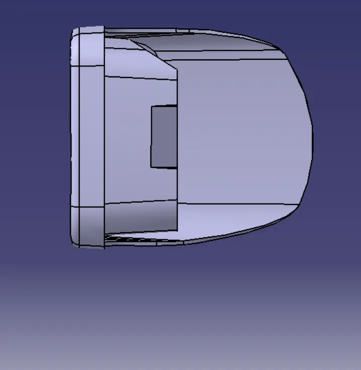
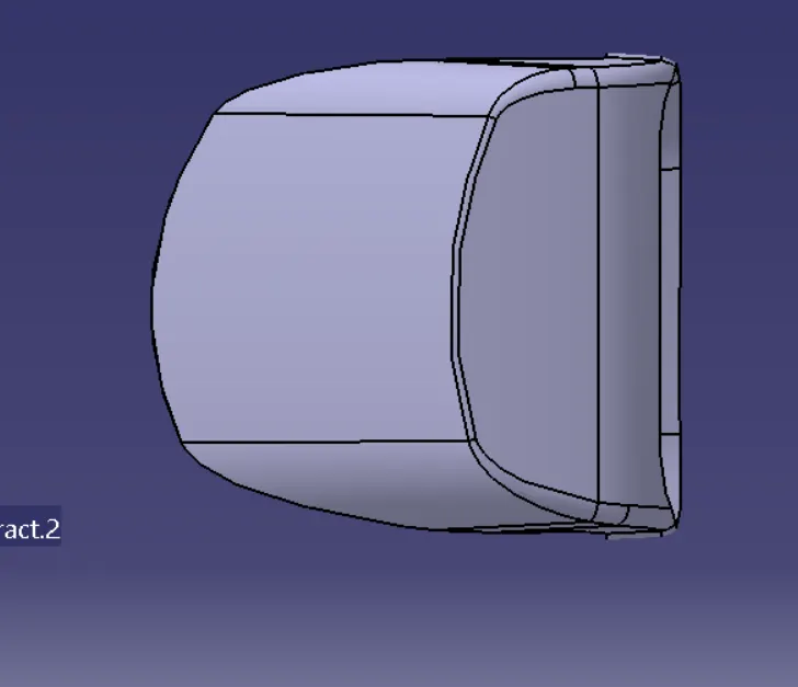
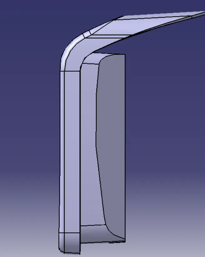
SIDE VIEWS ARE GIVEN BELOW:
DRAFT ANALYSIS:
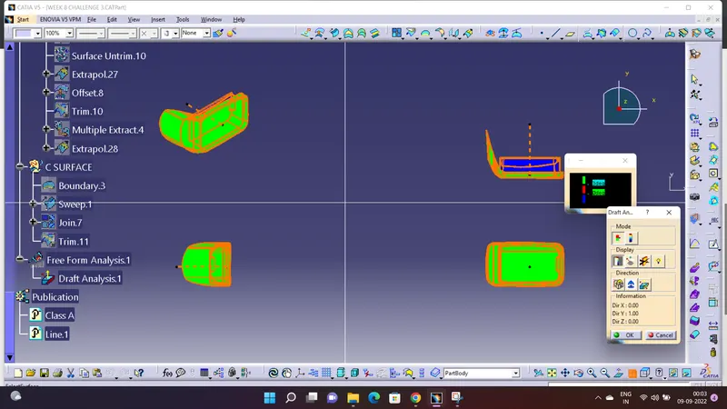
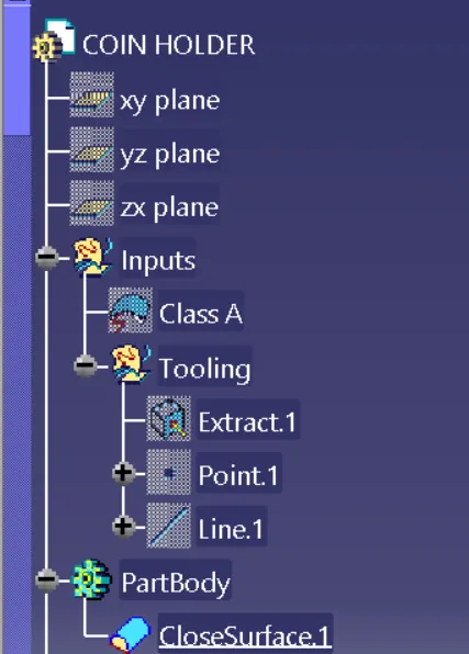
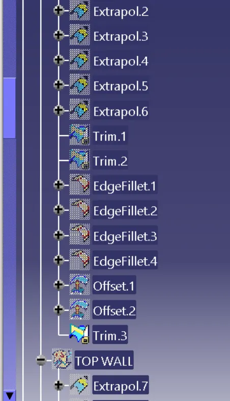
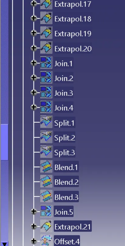
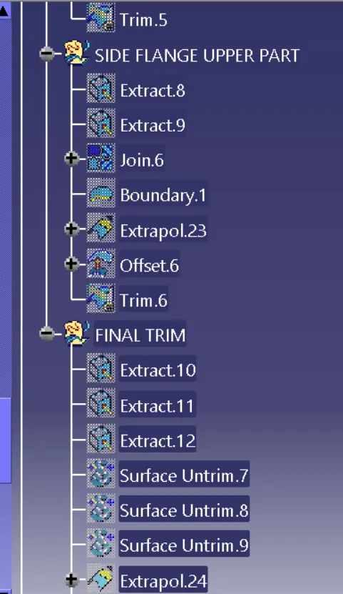
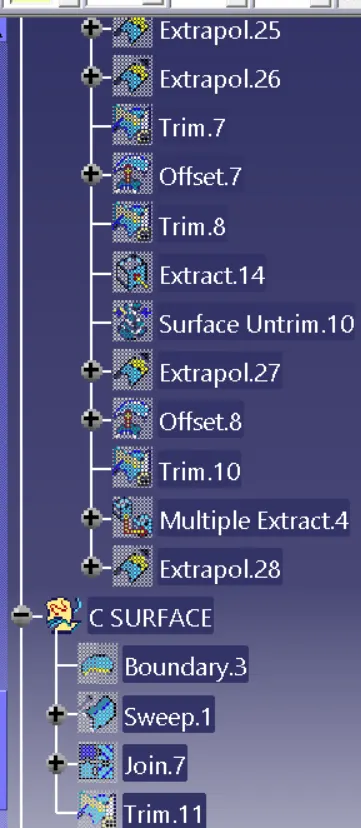
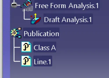
FEATURE TREE OF THE MODEL:-