3D Meshing and its types
AIM: To perform 3D Meshing on the given components by using either of the following methods:
- By converting 2D elements to 3D
- Volume Tetra Mesh
- Quick Tetra Mesh
CONVERTING 2D ELEMENTS to 3D:
Procedure for converting 2D elements to 3D:
- Import file to hyper work
- Geometry clean-up
- Defeaturing
- Assign quality criteria
- Meshing
- Quality error's clean up
- 3D meshing (TETRA MESH)
- Check for Tet Collapse errors
IMPORTING STEP FILE HYPER WORK:
Since we are importing a CAD geometry, the format will be either of the 2 industrial accepted standards:
STEP (Standard for the Exchange of Product data).
IGES (Initial Graphics exchange specification).
When selecting the file for import, be sure to check if it is .STEP or . IGES.
Go to File >> Import >> Select geometry >> Change to . STEP >> Open the model >> Click the model >> Import
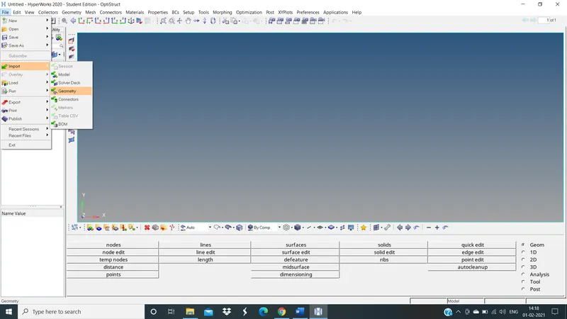
IMPORTING THE MODEL
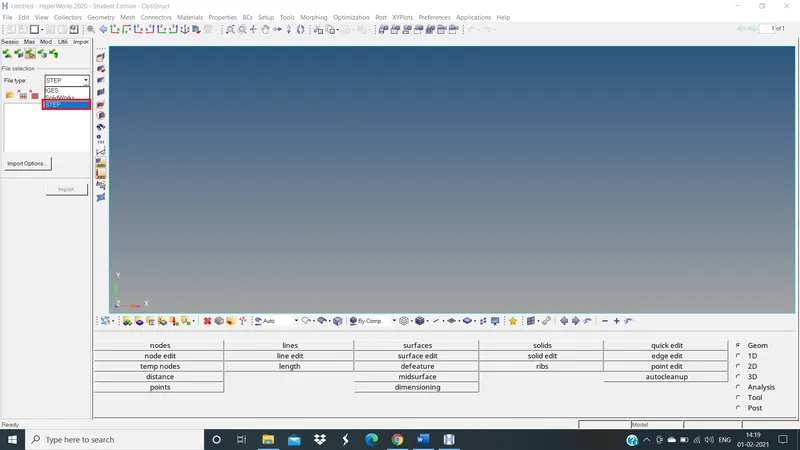
SWITCH THE FILE TO .STEP
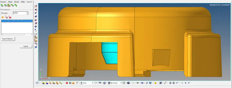
MODEL IMPORTED
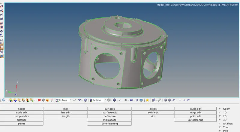
Now change the AUTO mode to TOPO mode to see the model imported is in solid are with out solid
Suppose imported model is in solid then we have to delete the solid component
Switch to Topo Mode, the solids will be highlighted in green colour .
Delete [F2] > Solids > Displayed > Delete Entity
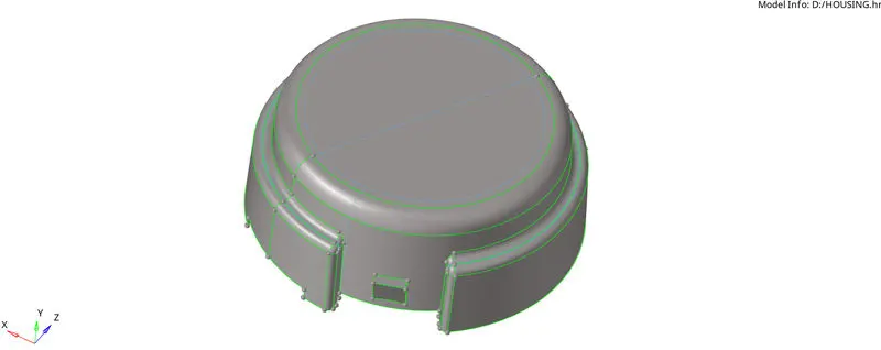
TOPO MODE
MODEL 1: HOUSING
MODEL 2: CRANK HOUSING
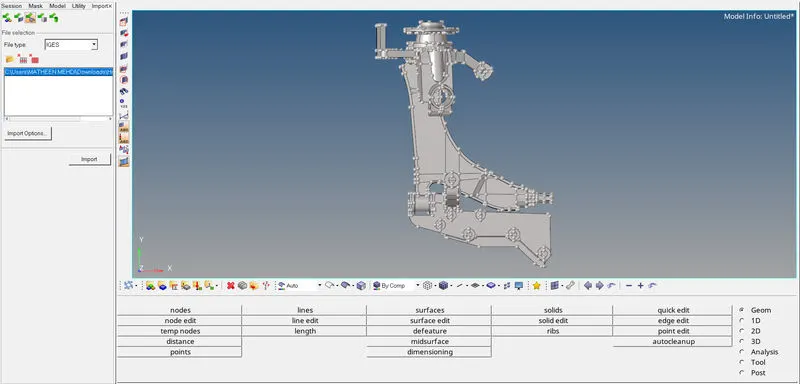
MODEL 3: Axle Assembly
we can see that there are 4 Components :
Hub
Knuckle
A-Arm
Part
GEOMETRY CLEAN UP:
Once the model is imported move to geometry clean up just to check whether there any extra surface or free edges or missing surface will present or not
Here in the above models no errors are present
To check a errors
Go to visualize panel >> Disable shared edges and all except free edges
DEFEATURING :
In hyper mesh, after you mesh a product for any kind of analysis, the end product is a meshed product. Most of the times it so happens that, some small holes or some small fillets or some small radii are left out which are not functional and unnecessary. We need to remove these unwanted features in order to obtain a final correct analysis. The process of removing these unnecessary, non-functional features is called de-featuring.
defeature all unwanted lines which is less than the given minimum length
For defeature
Go to quick edit >> Toggle all unwanted lines
ASSIGN QUALITY CRITERIA :
Assign quality criteria for a given model
Go to preferences >> criteria file setting >> Enter the values >> ok
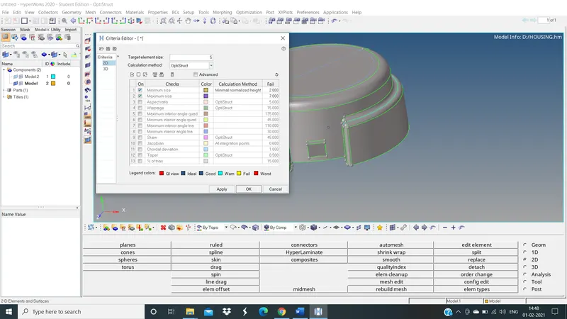
2D QUALITY CRITERIA
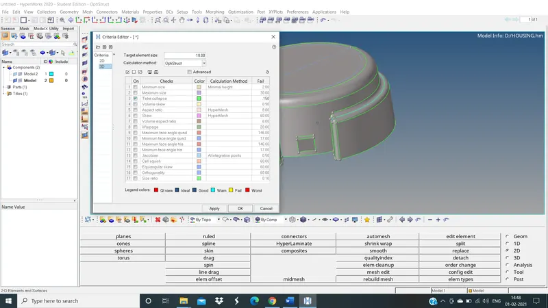
3D QUALITY CRITERIA
After assigned a given criteria now, we have meshed the model
MESHING:
FEA stands for the finite element analysis which means that elements are analysed and integrated over a region to derive the final result. so, in a continuous member, which in reality are everything starting from a pin to automotive parts. there are infinite nodes and it’s not possible to solve an infinite equation. so meshing is carried out so that we can desecrating that continuous member into number of finite nodes. and hence go for solving the equations. after that interpolate the results for entire domain.
Mesh the given components with a given quality criteria
Here given criteria is
MAX length: 7
MIN length: 2
TARGET length: 5
Now mesh the component
Go to geometry page >> Select 2D >> Select auto mesh >> Select surface >> Create
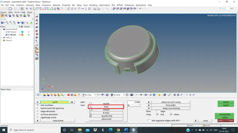
Here we are performing 3D mesh so here we have tria instead of quads
Now meshed the 2D surface first then convert 2D mesh to Tetra mesh
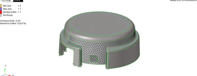
MESHED SURFACE BY SURFACE
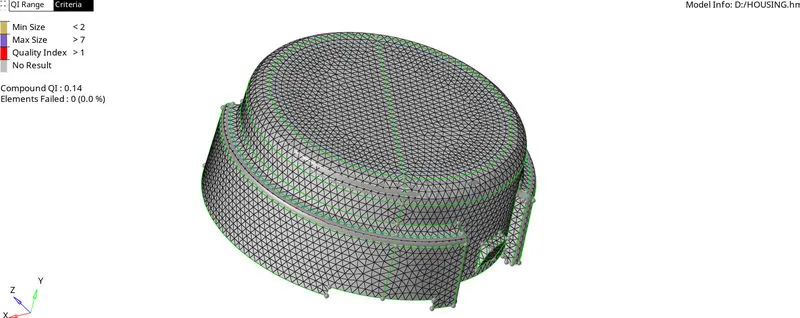
2D MESH
QUALITY ERROR CLEAN-UP:
Clear all the quality errors which are failing for the given quality criteria
After meshed a surfaces simultaneously clear all the error's
We can fix some errors by Quality Index tab
Go to >> 2D >> Quality Index >> Smooth
3D MESHING (TETRA MESH):
We are going to convert the existing 2d elements into 3D Tetrahedral elements by filling up the volume.
Steps for 3D meshing:
3D >> Tetra mesh >> Fixed Trias/Quads to Tetra mesh: Elems >> Displayed >> Mesh

3D PAGE

TETRA MESH
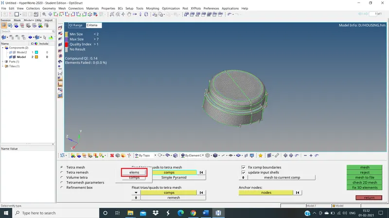
SELECT THE ELEMENTS
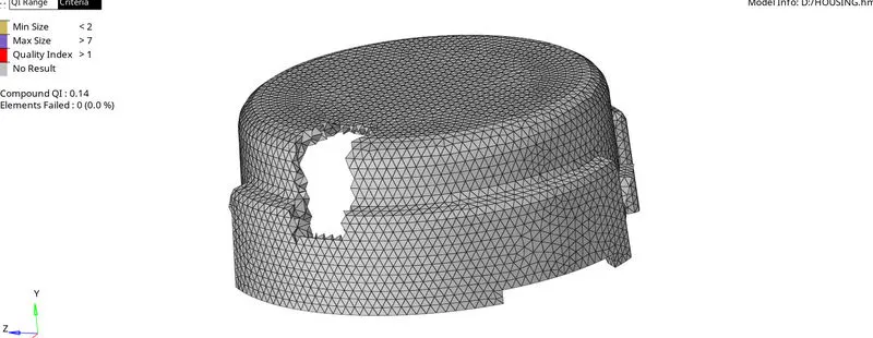
2D MESH IS CONVERTED 3D TETRA MESH
CHECK FOR TET COLLAPSE:
There is only one quality to check for 3D meshing, that is the Tet Collapse.
To check for Tet Collapse:
Tools >> Check Elems [F10] >> 3D >> Tet Collapse 0.15 >> Save Failed
Check the status bar to view the number of failed elements.
The status bar is present in the bottom left corner.
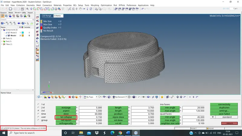
As we have already fixed for 2D Element Quality on the surface, we have only 149 Tet Collapse errors.
we can fix this error by manually or by remeshing the tetra elements

CHECK ELEMENT TAB
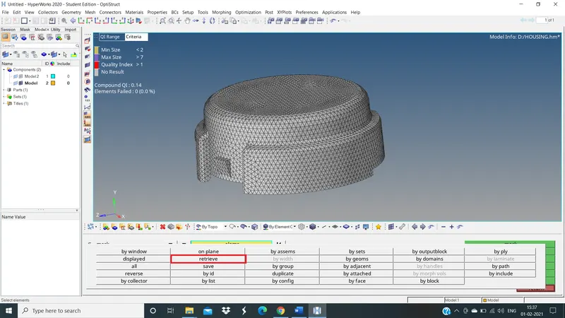
After clicking save failed in check elements
We have to go to mask command >> retrieve the failed elements >> mask >> reverse
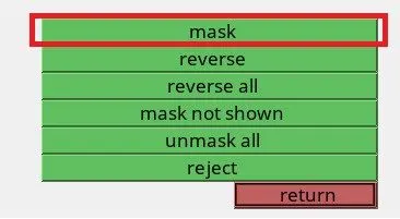
MASK COMMAND
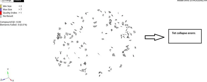
TET COLLAPSE ERROR
Now we have to remesh this 3D elements to fix the Tet collapse error's
For that
Go to 3D >> TETRA MESH >> Tetra remesh >> Select the save failed elements with adjust elements >> Remesh

TETRA REMESH
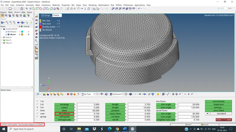
ZERO TET COLLAPSE ERROR
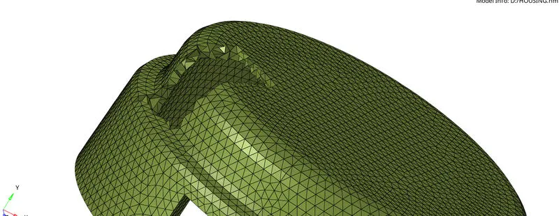
Mask the elements to see volumetric mesh (Tetra meshed )
VOLUME TETRA MESH:
Procedure for volume tetra mesh:
- Import file to hyper work
- Geometry clean-up
- Defeaturing
- Assign quality criteria
- Volume mesh
- Check for Tet Collapse errors
IMPORTED THE 2ND COMPONENT OF HOUSING :
The 2nd component of housing which in solid so its easy to perform volume mesh to the solid component
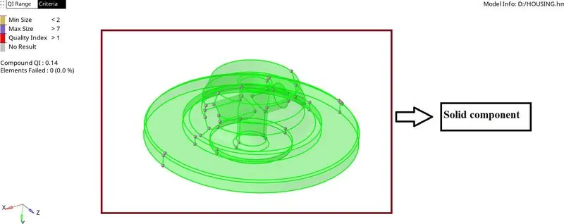
GEOMETRY CLEAN-UP:
Here in this component no geometrical error are formed
DEFEATURING:
Defeaturing is also no needed
Because no line is failing for minimum length
ASSIGN QAULITY CRITERIA:
Assign quality criteria for a given model
Go to preferences >> criteria file setting >> Enter the values >> ok
VOLUME MESH:
We will create a 3D mesh with the Volume Tetra Mesh panel:
3D >> Tetra Mesh >> Volume Tetra
Enter the following conditions:
Enclosed Volume: Solids
2D Type: Trias
3D Type: Tetras
Element Order: First
Elem size= 5 mm
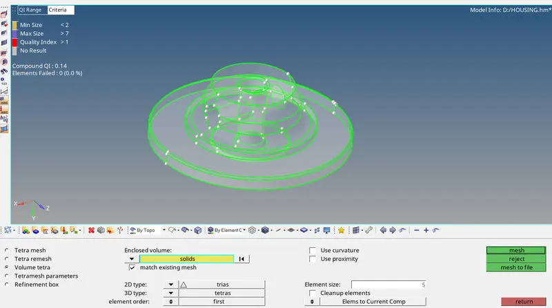
VOLUME TETRA
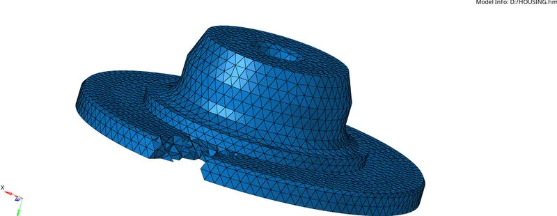
VOLUME TETRA GENERATED
MODEL 2: CRANK HOUSING
Volume tetra mesh
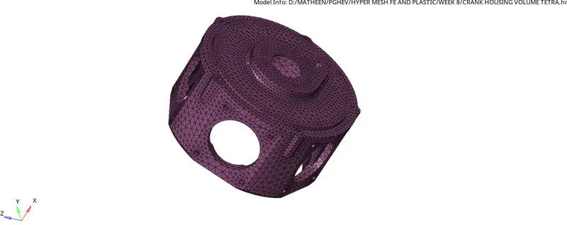
VOLUME TETRA MESHED
MODEL 3: Axle Assembly
we can see that there are 4 Components :
- Hub
- Knuckle
- A-Arm
- Wish bone
HUB:
Volume tetra mesh
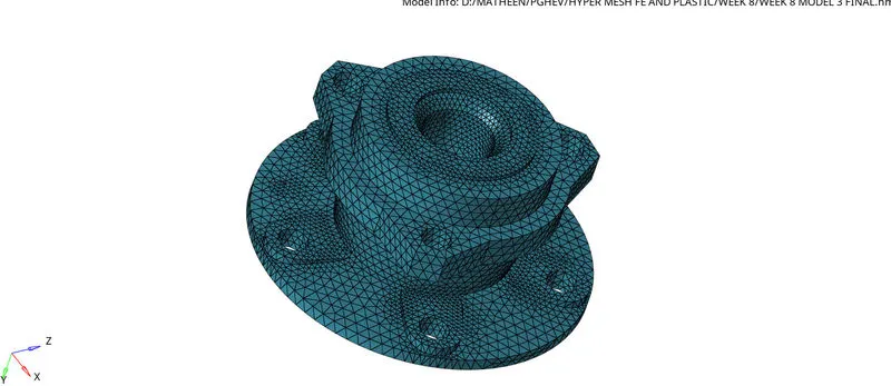
HUB
WISH BONE:
Quick Tetra Mesh:
Procedure for Quick tetra mesh:
- Import file to hyper work
- Geometry clean-up
- Defeaturing
- Assign quality criteria
- Utility tab
- Quick tetra (Both 2D and 3D)
- Check for Tet Collapse errors
Import component
Geometry clean up
Defeaturing
Assign quality criteria
All four of them are same as above what we explain
UTILITY TAB:
We will create a 3D mesh from the Utility Panel:
Tool bar >> View >> Browser >> Hyper mesh >> Utility
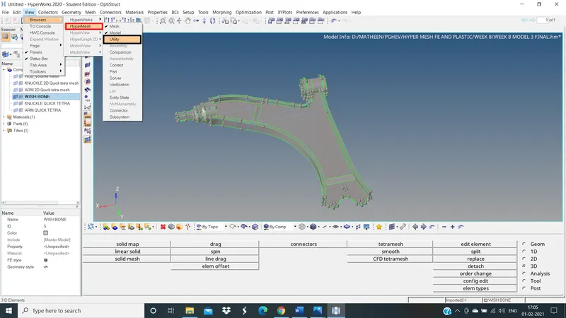
The Utility Menu will be opened in the Taskbar to the left of the UI.
Click on Geom/Mesh >> Mesh Tools >> Quick Tetra mesh
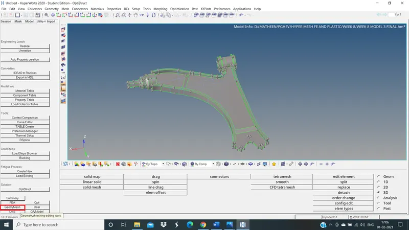
UTILITY TAB
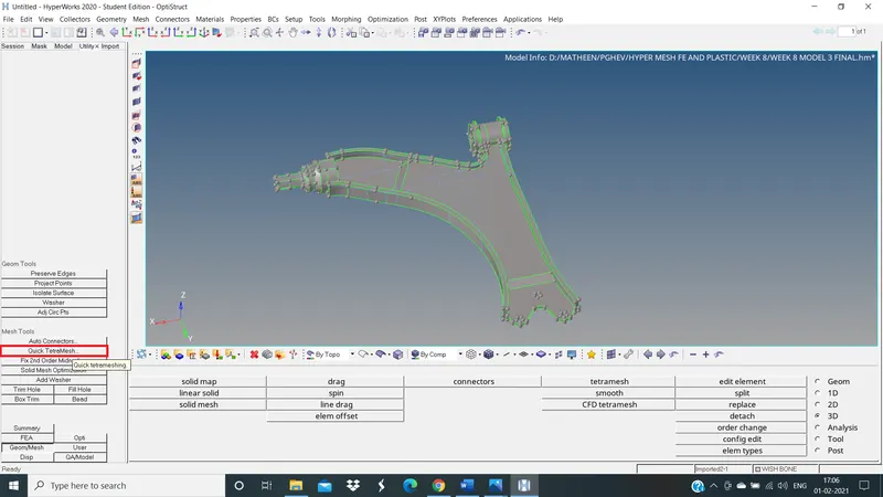
QUICK TETRA
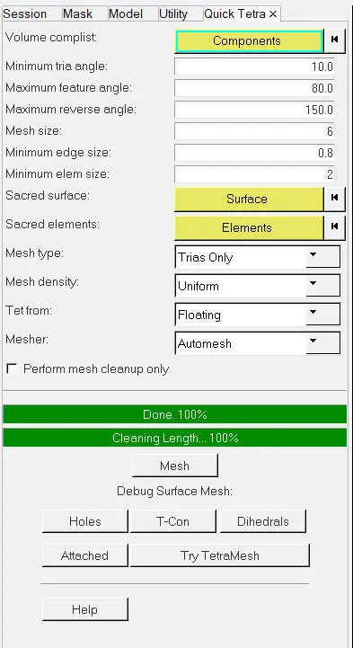
In the Quick Tetra mesh Tab:
We have to select the respective component we wish to mesh:
Volume comp list: Components (Command window will open)
Check for the Part you wish to 3D Mesh > Proceed
Enter the Quality criteria:
Mesh Size: 6 mm
Mesh Type: Trias only
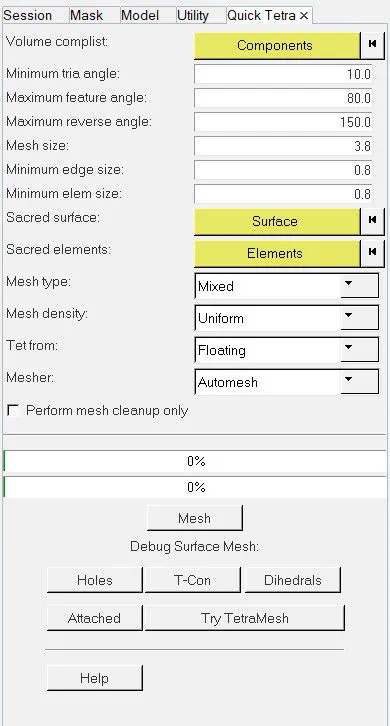
QUICK TETRA TAB
QUICK TETRA GENERATED
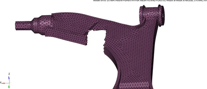
TETRA ELEMENTS
DIFFERENCE BETWEEN THREE TYPE OF 3D MESH:
- CONVERTING 2D ELEMENTS to 3D: Industry Preference: Most preferred as we have control of element and quality
Feature capturing: Very good feature capturing
Mesh Quality: Good mesh flow
2. VOLUME TETRA MESHING:
Industry Preference: Least preferred as it only gives a rough mesh
Feature capturing: Features are not captured well
Mesh Quality: Rough Mesh flow
3. QUICK TETRA MESHING:
Industry Preference: Preferred when quality is not important
Feature capturing: Complex features won't be captured well
Mesh Quality: Average Mesh flow
LEARNING OUTCOMES:
- Learned how to fix the geometrical errors to clean up the geometry.
- Learned how to Convert 2D mesh to 3D mesh.
- Learned how to fix quality errors.
- Learned how to meshed as per the given quality criteria.
- Learned how to mesh with volume tetra mesh.
- Learned how to mesh with quick tetra
- Learned how to resolve Tet collapse in 3D mesh.
RESULT: Tetra mesh is created for the given model's as per the given quality criteria using HYPERMESH
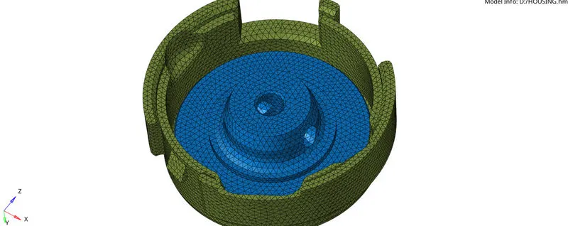
1. HOUSING MODEL
2. CRANK HOUSING MODEL
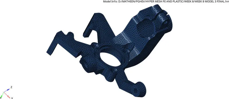
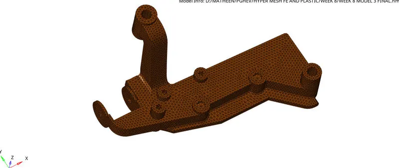
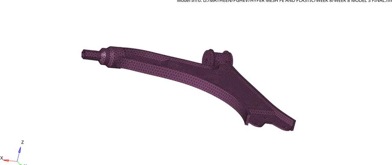
3. AXLE ASSEMBLY
CONCLUSION:
Here we learned the difference between all three type of 3D mesh compare to all three type of mesh converting 2D to 3D mesh will give good mesh flow but this will take more type compare to other 2 type but good feature capturing will be there in 2D to 3D