Week 8 - Challenge 2 - Base Bracket Design
BASE BRACKET DESIGN.
AIM: To create the solid part body of BASE BRACKET. From given bracket class A surface.
OBJECTIVE: The objective of this challenge is to create BASE BRACKET DESIGN along with solid part body from class A surface following OEM standards in CATIA SURFACE WORKBENCH and PART DESIGN.
INPUT CLASS A SURFACE:
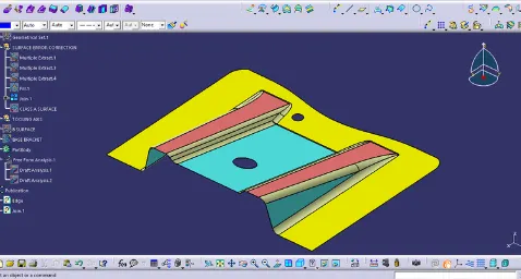
SOLID PART BODY
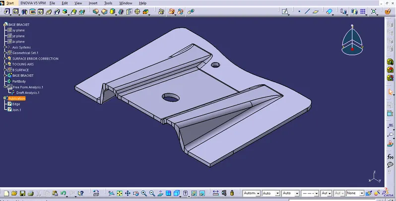
DESCRIPTION:
Four stages of design life cycle are as follows:
CONCEPT SKETCH: These are the imaginative and innovative sketches. Concept sketches can be defined as collection of visual cues sufficient to suggest the design to an informed observer. These are the basic sketches which provides general idea about design of the product. these sketches are provided to system either in 2D or isometric form. Example, concept sketch of an automobile.
Class a creation: Class A surface refers to those surfaces to those surfaces which are VISIBLE and abide to the physical meaning, in a product. For styling class-A surfaces of automobiles ALIAS software is used. These class A surfaces are used as an input for an Automotive plastic designer.
CLAY MODELLING: In clay modelling class A surfaces are provided to clay modeler who designers actual model is co-related using clay modelling physical representation of design is possible which helps in further modification in the design of the vehicle. Clay modelling of an automobile is the most common example of a clay modelling.
NPD CAD: NEW PRODUCT DEVELOPMENT. Computer aided drafting (CAD). This process involves forming strategy, organizing requirements, general concepts, creative product.
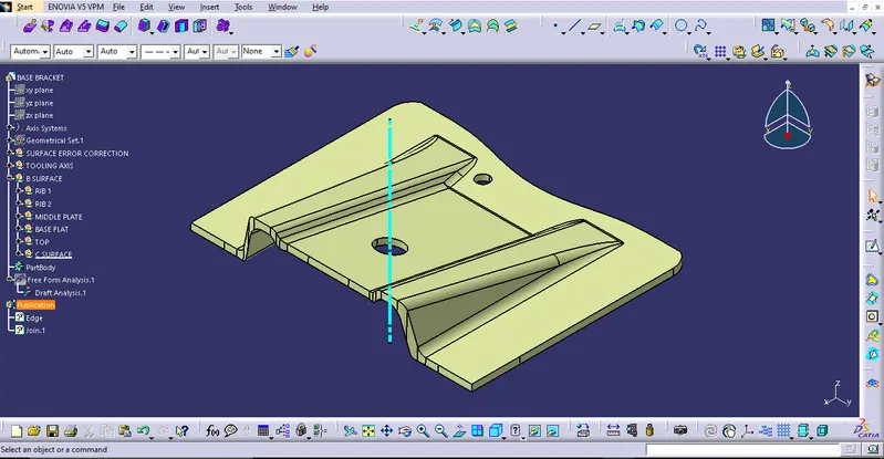
TOOLING AXIS CREATION:
CLASS A surface is first analysed to create tooling axis or tooling direction that moulds pull apart in injection moulding. Tooling direction is vital for plastic product design as it decides direction for mould separation.
Steps followed for creation of tooling axis:
1.References point is first created on extracted surface.
- New axis system is deployed to plot clearance surface.
3.The X direction and Y direction along class A were used to creating tooling axis
4.Two clearing lines were bisected to form Tooling axis.
5.Graphic properties of tooling axis were changed before publishing.
DRAFT ANALYSIS:
Draft angle: The draft angle is the amount of taper for modelled or cast parts perpendicular to the parting lines, it can be measured in degrees or mm/mm. As plastic cools, it shrinks and therefore shrinks into moulding surfaces. Because of this and a few other reasons, we draft(angles) the walls of the plastic part, so as the part is removed dragging. A functional part for injection moulding has to have drafts facing both cavity and core sides to reduce the risk of damages to the parts and ensure ejection. What’s also important is to overcome the vacuum forces by letting air in between the metal and plastic for the part to release properly. Adding an adequate draft angle ensures that wrappage upon ejection is prevented while maintaining a decent cosmetic finish.
Draft angles are generally a requirement of injection moulding design (though there are select few h
soft materials, like nylon, that can get away with draft angles of zero).
Draft should be a part of design for manufacture, and plastic product designer should be aware of its needs at the outset of the design process. This allows considerations for design requirements taken into account.

Nominal draft angles:
1.3-degree draft angles in nominal draft.
2.5 degree can also be manufactured. But it will increase the manufacturing cost.
3.7 degree for textured surface.
Importance of draft in injection moulding:
Reduces the chance of damage to the part due to friction during release
Reduces wear and tear and chances of damage to the mould
Ensures a uniform, smooth, unscathed finish when required.
Ensures high integrity and uniformity of other surfaces finishes and textures.
Reduces overall cooling time by lessening the or eliminating the need for unconventional ejection setups
Most, if not all, of these benefits offer direct or indirect overall production cost reductions.
Steps followed for draft angles:
- The part created has to be changed to material mode in display frame.
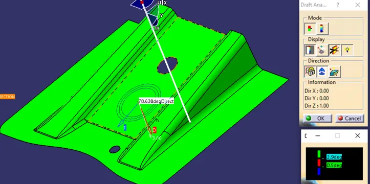
- Compass is enabled. Align compass along with tooling direction.
- Lock command is then applied to fix the compass along with tooling axis
- Colour codes are classified and draft angle is applied.
- Running point analysis is used to display permissible draft angle.
DRAFT ANALYSIS REPORT
DRAFT ANALYSIS ON CLASS-A SURFACE: