Week 8 - Challenge 2 - Base Bracket Design
CLASS A
In automotive design, a class A surface is any of a set of freeform surfaces of high efficiency and quality. Although strictly, it is nothing more than saying the surfaces have curvature and tangency alignment – to ideal aesthetical reflection quality, many people interpret class A surfaces to have G2 (or even G3) curvature continuity to one another (see free form surface modelling).
Class A surfacing is done using computer-aided industrial design applications. Class A surface modellers are also called "digital sculptors" in the industry. Industrial designers develop their design styling through the A-Surface, the physical surface the end-user can feel, touch, see etc.
A common method of working is to start with a prototype model and produce smooth mathematical Class A surfaces to describe the product's outer body. From this, the production of tools and inspection of finished parts can be carried out. Class A surfacing complements the prototype modelling stage by reducing time and increasing control over design iterations.
Class A surfaces can be defined as any surface, that has styling intent, that is either seen, touched or both and mathematically meets the definition for Bézier.
- Automotive design application
- Product design application
- Aerospace design application
- Clay modelling
- Notable software
CLASS B
It's the surface created from extracting the class A surface with all their faces and adding support features like ribs, dog houses, stiffeners for maintaining its stability and strength for the surfaces.
CLASS C
Class C is the thickness added to the Class B surface and it is in 3D since the direction is in the Z direction of the component.
Reason for tooling axis selection
- In both X and Y directions the fan cover geometry was not covered or visible so by selecting the Z direction entire geometry will be covered
- In X there is a side cut by reference to the boundary so the feature will not be captured.
- In Y there is a hole by reference to the boundary so the feature will not be captured.
PROCEDURE
*Create an intersection between the ZY plane and the Base Bracket.
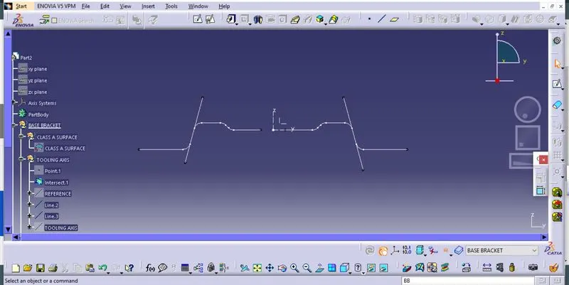
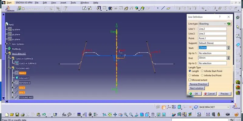
*Creating lines by point to point method and bisecting the lines to create the TOOLING AXIS.
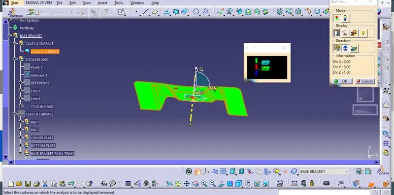
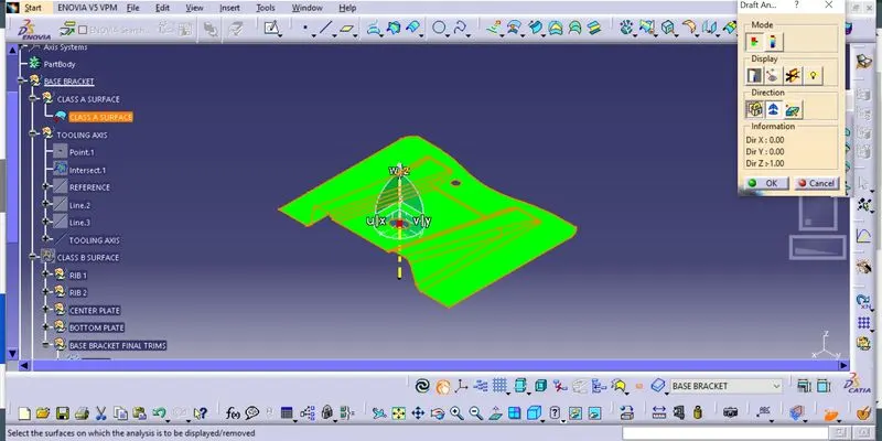
*Draft analysis for the Base Bracket by quick analysis mode.
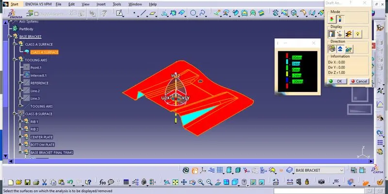
*Draft analysis for the Base Bracket by Full analysis mode.
*Draft analysis for the Base Bracket in Isometric view.
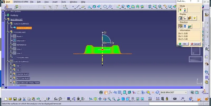
*Draft analysis for the Base Bracket in Front view.
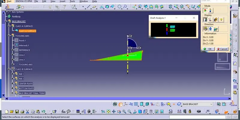
*Draft analysis for the Base Bracket in Side view.
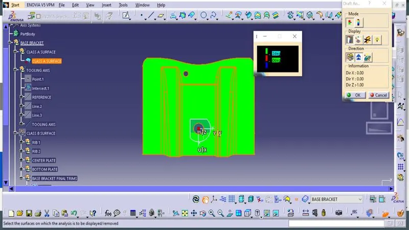
*Draft analysis for the Base Bracket in Top view.
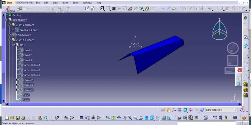
*Class B surface RIB 1 after extract, Surface Untrim, Extrapolate, Trim.
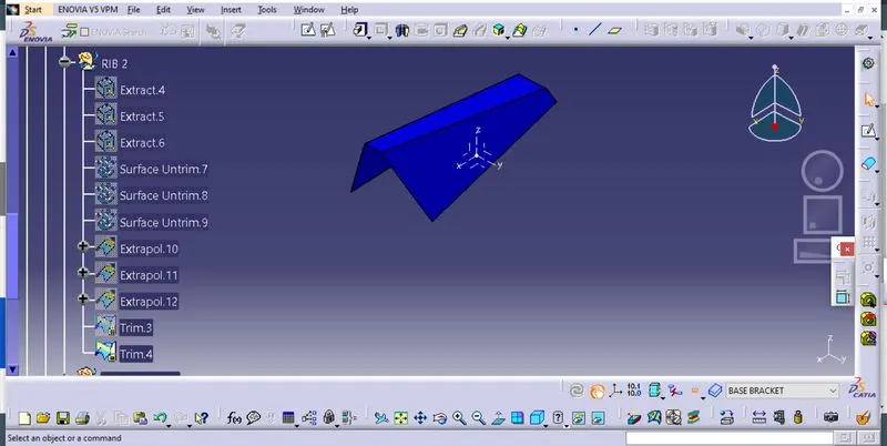
*Class B surface RIB 2 after extract, Surface Untrim, Extrapolate, Trim.
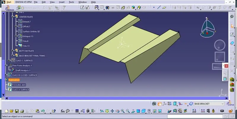
*Class B surface CENTER PLATE after Extract, Offset, Surface Untrim, Extrapolate, Trim.
*Class B surface CENTER PLATE after Extract, Offset, Surface Untrim, Extrapolate, Trim.
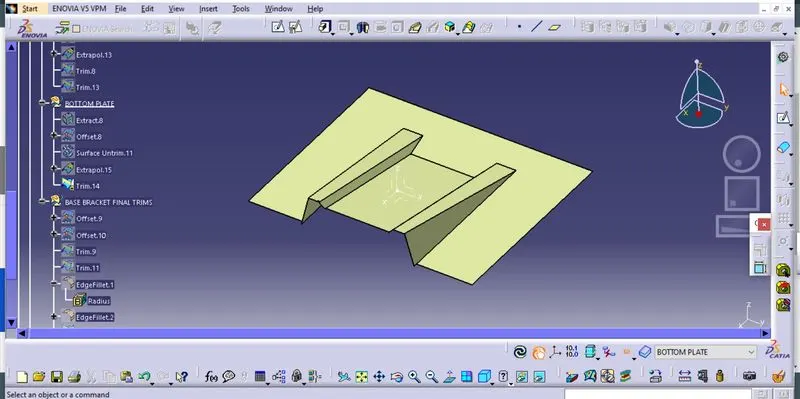
*Final Class B surface.
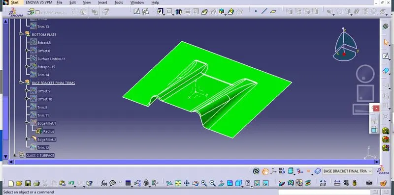
*Final Class C surface.
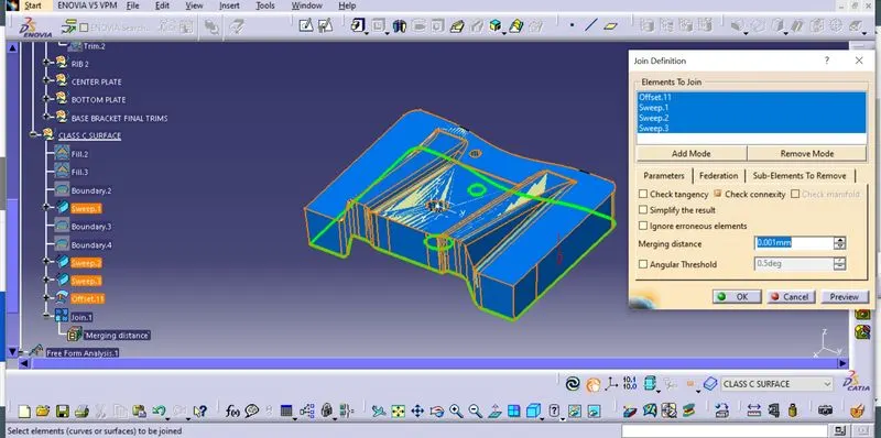
*Final surface of the back bracket with 2.5mm thickness.
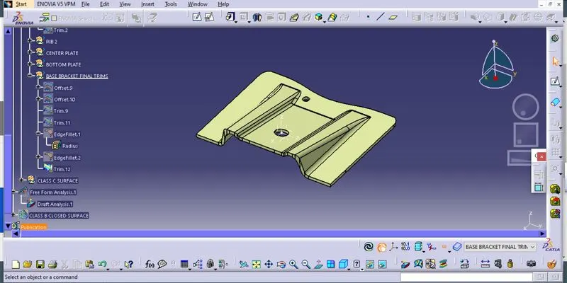
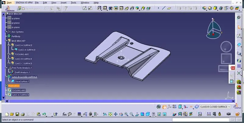
*Final surface of the back bracket with Close Surface.
CONCLUSION:-
- A detailed report is been done explaining the draft analysis and the tooling axis creation.
- An explanation is been given on the way of creating the tooling axis by Bisecting method.
- Screenshots of the Draft analysis report.
- Image of the complete Draft analysis.
- Images of the color scale variant.
- Screenshots of the model with the proper color code of the draft angle in various orientations (Isometric, Front, Side, and Top View.