Week 8 - Challenge 1 - Draft Analysis on a Fan Cover
Draft:
In engineering, Draft is the amount of taper for molded or cast parts perpendicular to the parting line. It can be measured in degrees or mm/mm (in/in) .The manufacture of a part that incorporates zero or negative angles may require a mold that can be separated into two or more parts, in order to release the casting.
Consider the fabrication of a hollow plastic box, without lid. Once the plastic has hardened around the mold, the mold must be removed. As the plastic hardens, it may contract slightly. By tapering the sides of the mold by an appropriate "draft angle", for instance 2° (two degrees), the mold will be easier to remove. This is a practice that is used, in applicable cases, when working with fiberglass.If the mold is to be removed from the top, the box should taper in towards the bottom, such that measuring the bottom internal dimension will yield a smaller length and width than measuring the top from which the mold is extracted.By specifying the opening length and width, a draft angle, and a depth, it is not necessary to specify the dimensions for the internal surface, as these may be calculated from the above.
Draft Analysis:
The Draft Analysis command enables you to detect if the part you drafted will be easily removed. This type of analysis is performed based on color ranges identifying zones on the analyzed element where the deviation from the draft direction at any point, corresponds to specified values.The draft analysis button within CATIA V5 will helps you quickly gather the draft angle on multiple surfaces without the need for tedious manual measurements.
Tooling Axis:
Tooling axis is the path thorugh which the tool moves through the core of the mold while creating a part in Molding process.Tooling axis should lie perpendicular to the surfrace and parting line.Tooling axis is very important in the process of molding as it is this axis which helps in the movement of tool.
Draft Analysis on a Fan Cover
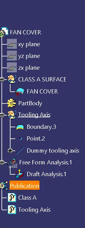
First the file was imported to Catia and then the Class A surface was retrieved. Then the Boundary was created and a point was created at the centre of the surface . And now as we have the centre of the surface the tooling axis was created at that point and then Draft analysis was performed on the surface and Analysis was carried out .
As mentioned earlier maximum of 3 degree is widely accepted in industry standards and 0 degree will allow contact of the moldedpart to the mold which we dont want and negative degree becomes impossible for th part to be removed from the mold unless it is destructable mold. And the quality of the draft angle is measured using varying colors in draft analysis. Here i have specified green for 3 degree draft and blue for 0 degree draft and red for negative draft.
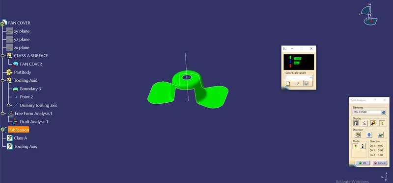
Tree structure:
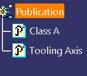
Publications:
Publications are used for easy reference , here Class A and Tooling Axis are clubbed under Publications.
- Screenshots of the model with the proper color code of the draft angle in various orientations (Isometric, Front, Side, and Top View):
Iso view:
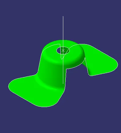
Front view:
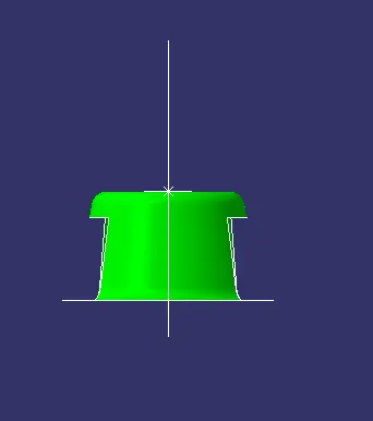
Back view:
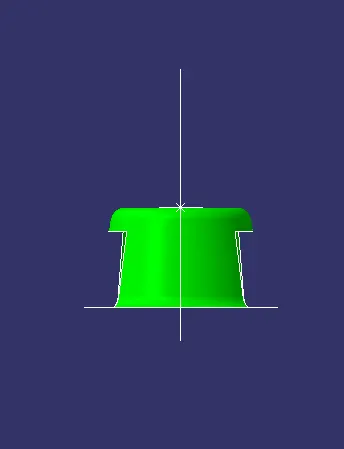
Left view:
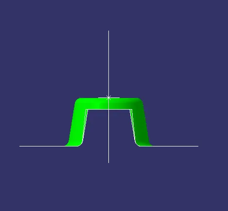
Right view:
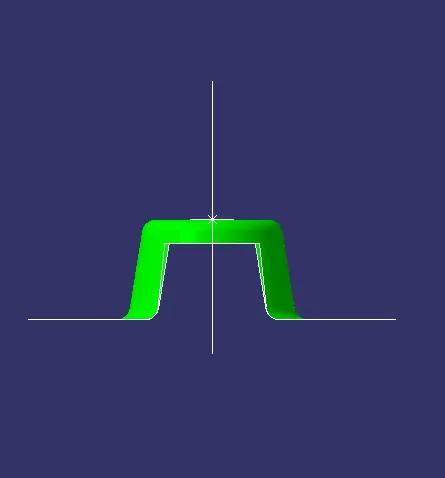
Top view:

Bottom view:

Conclusion:
Thus the draft analysis was performed after creating right tooling axis which goes perpendicular to the surface.