Week -2
Simulink model of Doorbell using solenoid block and Usage of a thermistor to sense the temperature of a heater & turn on or turn off the fan as per user conditions.
1.)Simulink model of Doorbell using solenoid block :
Aim:
To create a simulink model of a doorbell using a solenoid block.
Exaplantion of a Doorbell and Solenoid:
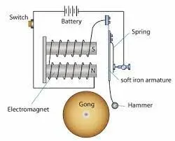
A doorbell is a signaling device typically placed near a door to a building's entrance. When a visitor presses a button the bell rings inside the building, alerting the occupant to the presence of the visitor.A solenoid is a device comprised of a coil of wire, the housing and a moveable plunger (armature). When an electrical current is introduced, a magnetic field forms around the coil which draws the plunger in. More simply, a solenoid converts electrical energy into mechanical work. Thus when a person presses the switch on the plunge gets triggered and moves to and fro towards the gong which is basically a piece of metal mostly made up of iron.
Simulink model of solenoid and doorbell connection:
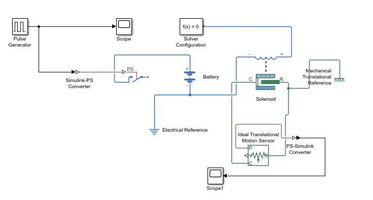
Blocks used to make this circuit:
Pulse generator:The pulse generator produces square wave pulse at regular intervals. The block wave form parameters,Amplitude,Pulse,Width,Period and phase delay determine the shape of the output waveform.
Scope:Display signals generated during simulation.
Simulink P-S converter:This block converts unitless simulink input signal to physical signal.
PS switch:This Switch is controlled by an external physical signal.
Battery:Battery block represents the a simple battery model which is the power source for the circuit.
Solenoid:It behaves as a model which shows electrical characteristics and generated force of solenoid.
Solver Configuration:The solver configuration block specifies the solver parameters.
Mechanical translational Reference:It is a block that represents the a reference point of all mechanical ports.
Electrical Reference:It is a block that represents the a reference point of all electrical ports.
Ideal Translational Motion Sensor:It is a block which senses the motion in mechanical translational ports.
P-S Simulink Converter:This block converts physical signal to simulink output signal.
Working Explanation:
- The pulse generator is used to give the unitless input signal , where Amplitude:1,Pulse width=50%,Phase delay =2 sec.
- The input signal is then converted into physical signal with the help of P-S converter and it is further sent to the switch.
- The switch once it gets signal from the user the loop is closed and it further send signal from battery to the solenoid .
- Now since the electrical signal is passed into the solenois a magnetic field is produced around the solenoid and it pulls the plunger to the gong.
- Thus here electrical energy is converted into mechanical energy.
- The ideal translational motion sensor then send signal to PS simulink converter where the output signal is displayed with the help of the Scope.
Output:
Scope:
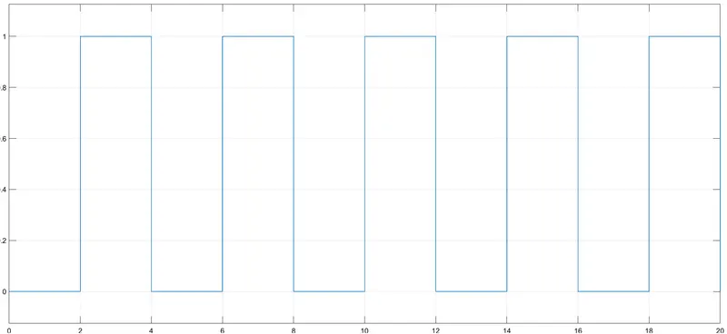
The above graphs represents the input signal in a graph .
Scope1:
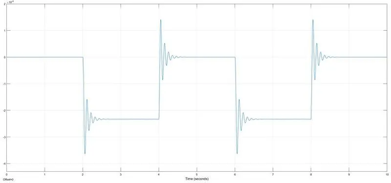
The above graph clearly shows that every 2 seconds the amplitude becomes 0 and at the end of every 2 seconds we can observe the plunger showing motion which is represented by the movement on the graph.
2.) Simulink modelling of a thermistor to sense the temperature of a heater & turn on or turn off the fan as per user conditions.
Aim:
To create a simulink model of a thermistor to sense the temperature of a heater & turn on or turn off the fan as per user conditions.
Explanation of a Thermistor:
A thermistor is a resistance thermometer, or a resistor whose resistance is dependent on temperature. The term is a combination of “thermal” and “resistor”. Thermistors are made from semiconductor materials, typically metallic oxides, using cobalt, manganese, or nickel.The working principle of a thermistor is that its resistance is dependent on its temperature, If we know the exact relationship between how changes in the temperature will affect the resistance of the thermistor – then by measuring the thermistor's resistance we can derive its temperature.

Above shown Image is a Thermistor.
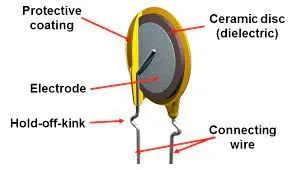
Above shown image are the parts inside a thermistor.
Simulink model :
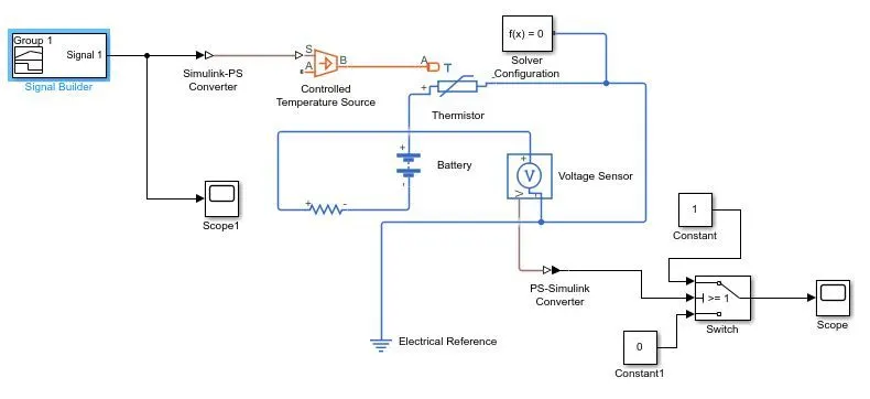
Explantion of model and Model blocks used:
Here in this model the signal builder is used for inputting the user signals which in this case is already specified and they are as follows:
Temperature source:
20 °C from 0 to 10 seconds,
27 °C from 10 to 30 seconds,
23 °C from 30 to 50 seconds , and these conditions are input into the signal builder in units of Kelvin , and these signals are then passed to the simulink PS converter to convert the input signal to physical signal. This signal is passed to the controlled temperature source which is the ideal source of thermal energy from here the signal passes to the Thermistor which is connected with the battery source then this thermistor and battery is coupled with the Voltage sensor to measure the volatge flowing thorugh the circuit the output from the voltage sensor is the converted into simulink signal with the help of PS simulink converter and this signal then goes to the conditional switch which has a threshold value with two constant values '1' and '0' , thus according to the input signal the switch evaluates the signal it is receiving and compares it with the threshold value and if the tempearture is above or equal to the threshold limit then '1' which is the 'switch on' comes as ouput else '0' which is the 'switch off' comes as ouput and this output is viewed with the help of the scope.
Input signal:
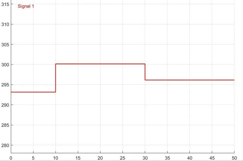
The above graph shows the input signal.
Output signal:
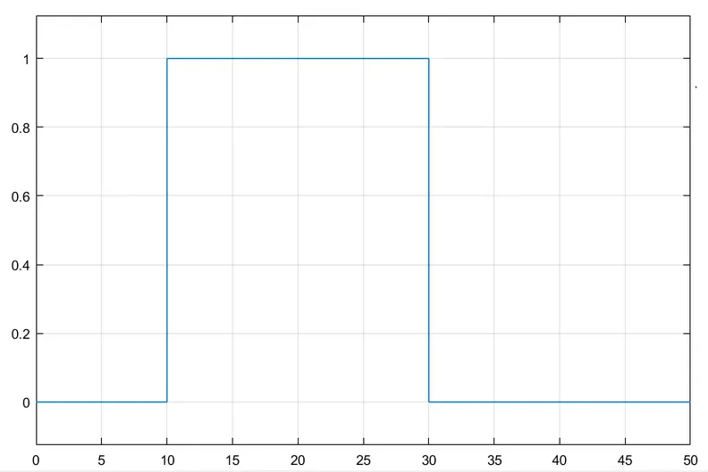
The above graph shows the output signal.
Conclusion:
Thus Simulink model of Doorbell using solenoid block and Usage of a thermistor to sense the temperature of a heater & turn on or turn off the fan as per user conditions is shown with the help of the models and graphs shown above and the experiment is successfully done.
Reference:
https://en.wikipedia.org/wiki/Thermistor