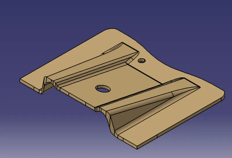
Week 8 - Challenge 1 - Base Bracket Design
TOOLING AXIS
The tool axis or the tooling direction is the direction in which the mold opens and closes.
Bisecting Method
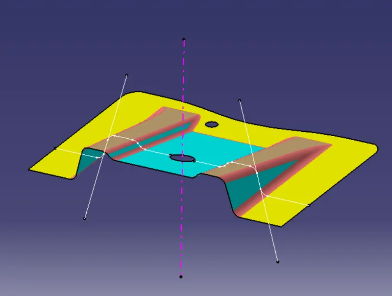
The bisecting method is the process of finding a secure tool axis for components along the draft direction. The method is to find the expected draft line that the tool axis draft angle may interfere with and make bisecting lines of the line to find the correct tool axis.
Procedure
- The given surface is inspected for opened boundaries, the inspection can be done using the ‘Boundary’ or ‘Join’ tool.
- All the possible tooling axis is considered after visual inspection and the best one is picked as a dummy tooling axis. To create the dummy tooling axis the surface with a large flat portion of the surface with holes is taken as reference.
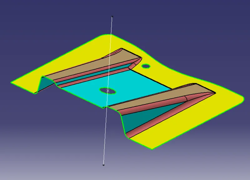
- The intersection boundaries are marked along the direction where the draft angle may be a problem.
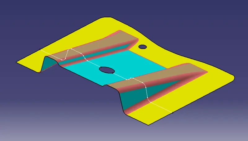
- Line is made along the direction where the draft angles expect to cause problems.
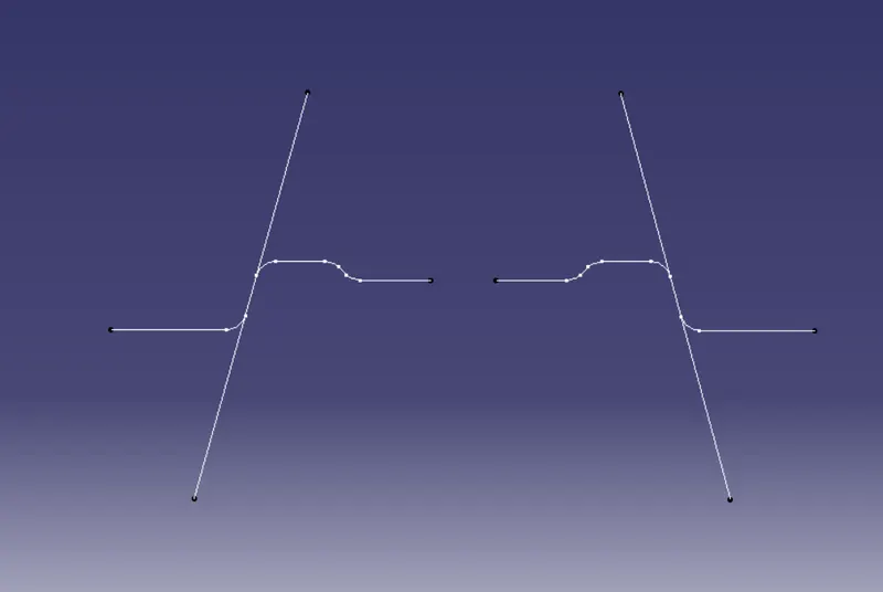
- The bisecting lines of these are made for every intersection. If there are multiple bisecting lines based on different intersection boundaries. These lines are bisected again to create the final tooling axis.
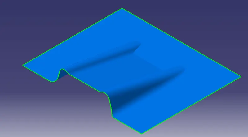
Class A surface
Class A surface is the given input surface of the model.
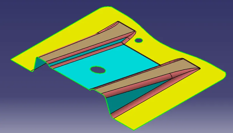
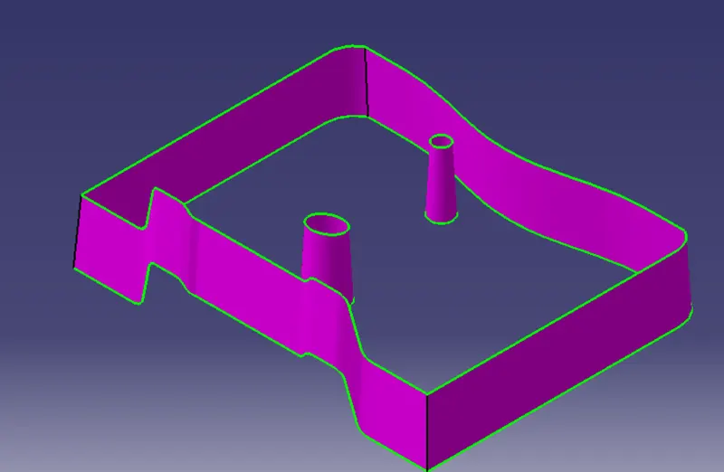
Class-B and Class-C Surface
Class B and C surfaces are the engineering and drafting surface based on the class-A surface. The class-B surface usually is an offset replica of the class-A surface and the class C surface is the surface connecting these two surfaces.
Draft Analysis
Draft analysis is the command or tool used to make sure the component that is made is maintaining the minimum draft angle with tool direction or not. Maintaining the minimum draft angle helps to retract or eject the model after the molding process. In CATIA there is a tool to check these processes called ‘Draft Analysis. After inputting the tool axis and the component to check the draft the toll color-coded the surface indicating the draft angle ranges that clear the minimum requirements and that failed to maintain the minimum requirements.
Class-A Surface Drafteng Analysis
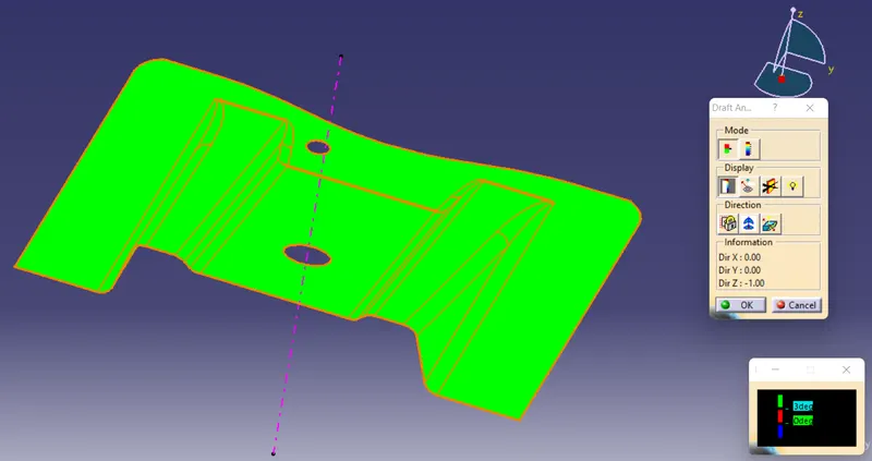
Closed Model Draft Analysis
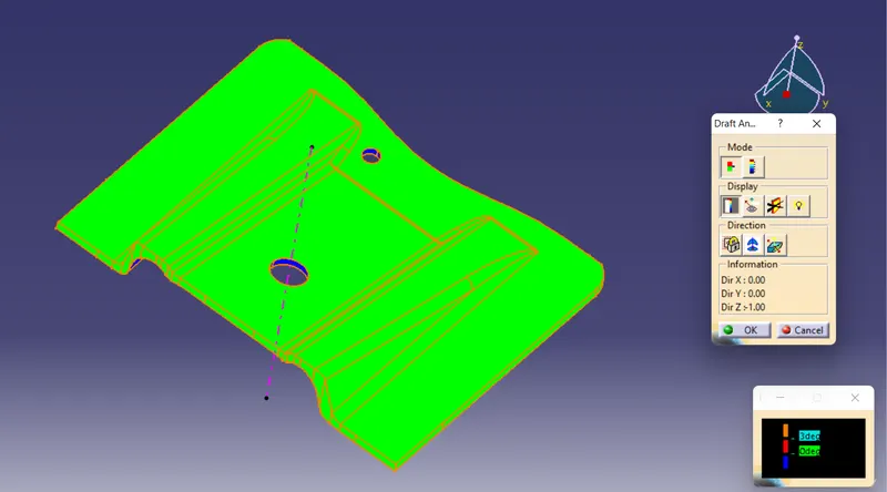
Solid Model
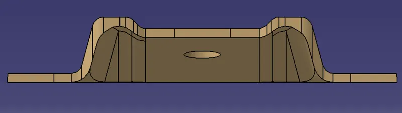
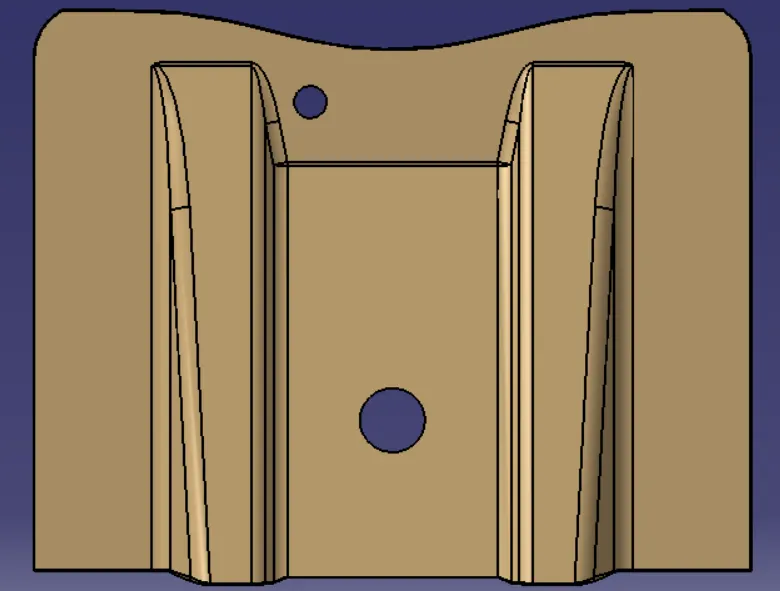
Front View
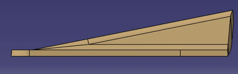
Side View
Top View
Isometric View