Week 8:- 3D Finishing Challenge 2
AIM
Perform 3D finish and create Rough locators for the Assembly design created for the challenge on week 7.
What is 3D Finishing
This is the final stage where the design process is completed and getting freezed (no modification in design after this). Then it is ready for final simulation to check for flaws and feasibility and 2D detailing.
The points need to be taken care of while finishing the design
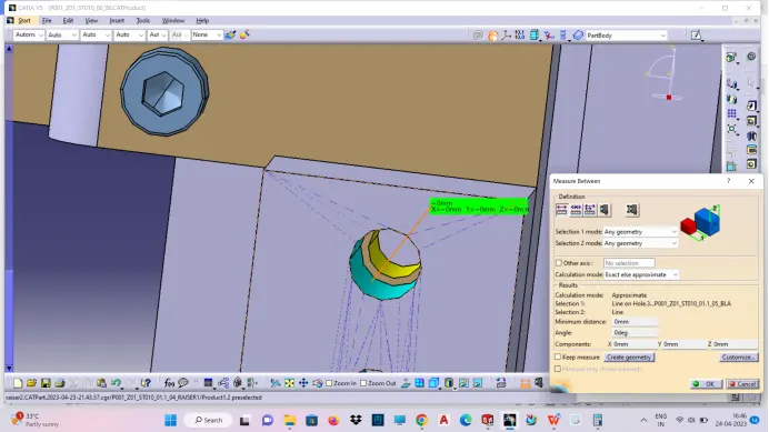
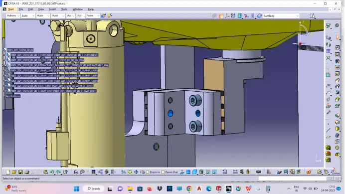
- Hole concentricity and sizes:All the holes of mating part in the fixture should be checked for hole concentricity.
- Avoiding clash between different parts:Standard gap should be maintained to avoid clash between different parts.
- Pneumatic Layout:pneumatic layout is collection of different pneumatic pipes which works as a inlet to the pneumatic cylinder. It should be done properly for proper functioning of the units.
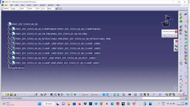
- Proper renaming of parts or assemblies as per the standards:It is done in the design tree consists of lot & lot of parts which ease in identification and modification of parts.
- Follow the hole colouring standard:It should be done as per the customer requirements.
- Machining area:The area should be defined and identified using standard colour code.
- Mylar splitting as per panel profile:The mating face of both rest and clamp mylar should be splitted along with the shape of work piece.
Hole concentricity and sizes
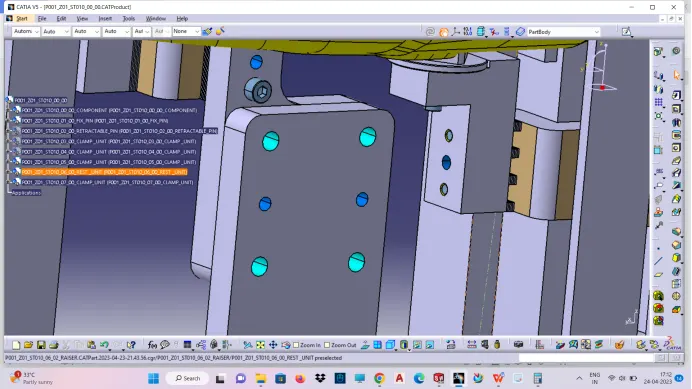
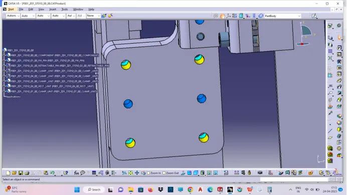
Follow the hole coloring standard
Yellow color - Threaded holes.
Cyan color - Free holes.
Blue color - Dowel pin holes.
Machining area
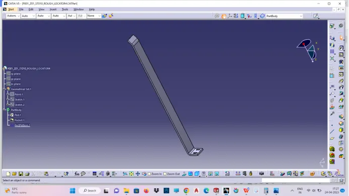
Rough Locators & what is their uses
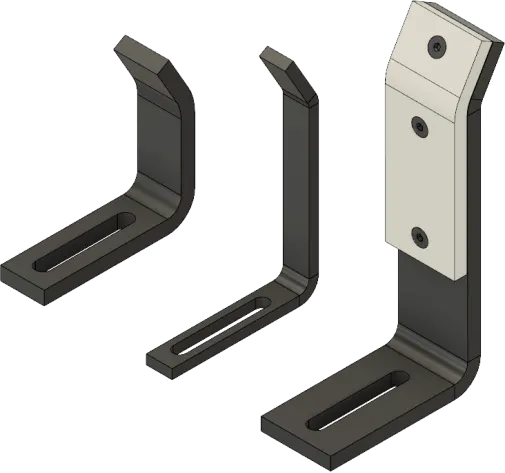
- Rough locators are used to position or locate the work pieceon the fixture pin in the automation process.
- The accuracy in the location of work piecedefines the quality of the final product.
- It is a fool proofingmethod because it positions the part/work piece with respect to the angle of respective panel.
The points you need to consider while designing a rough locator?
- The pin top must be above 10 to 15 mm from the top surface of workpiece at the particular location.
- The tip of rough locator is designed with a particular entry angle it ranges between 30 t 45 degree which eases the entry of workpiece.
- Rough locator has to be placed in the same angle of the car part edge with a minimum distance of 2-5 mm from the edge of the car part.
- The rough locator must have slot in the direction of car panel guiding.
- The rough locator should guiding the panel before 10 to 15 mm to the start of pin engagement.
The gun study process
- It is the process of checking feasibility of whether the gun is able to weld at the car panels selected weld spot point.
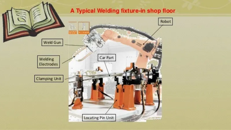
- The below images shows the weld gun doing spot welding and the weld location where the spot is created on the car panel.
- Gun study is necessary as the BIW fixture design.
- In 3D software gun study is done by actually introducing welding gun in fixture that we have designed, at all the individual points by placing the electrode using constrain option and check for clash between gun assembly and car panel or some other components in fixture.
- If the clash occurs between any of the component, rectify it by adjusting the shape or size or orientation of the parts.
- According to that units are designed so that there's no problem while welding process.
The points need to consider during the gun study
- The weld electrode axis must be perpendicular to the surface of the workpiece.
- Check for standard clearance between gun assembly and parts while at welding and movement from one weld point to other point.
- It ensure that the gun should not colloidor clash with any of the component in the assembly.
- The number of weld spots and the time required for welding at each spot shows the total time required for spot welding.
- Robot cycle time is calculated while doing proper gun study.
Collision checking is done on simulation software to check whether the welding process is done without any collision with any units in fixture.
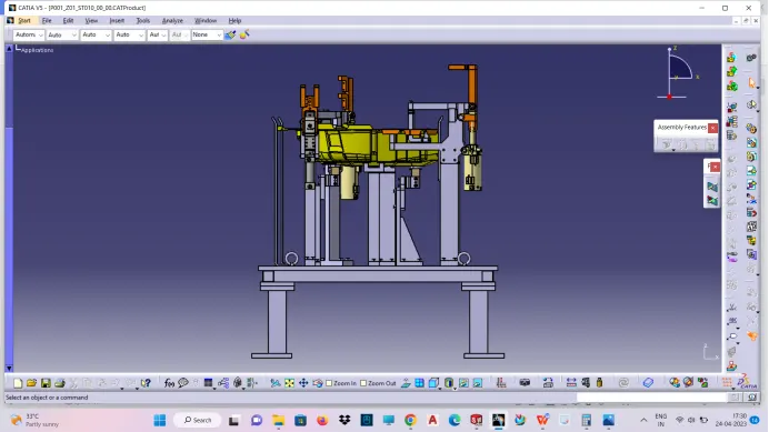
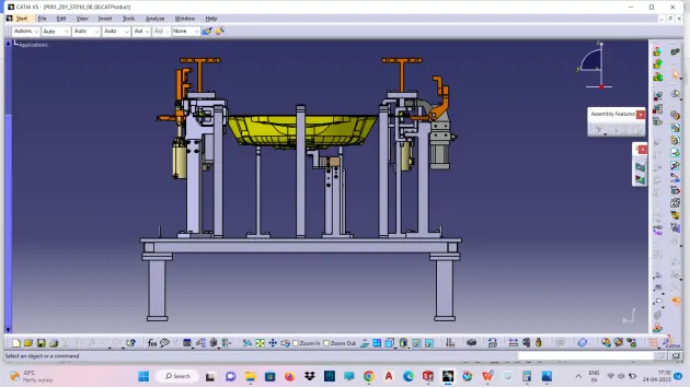
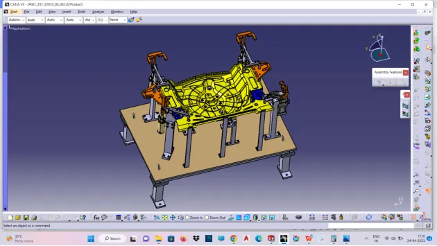
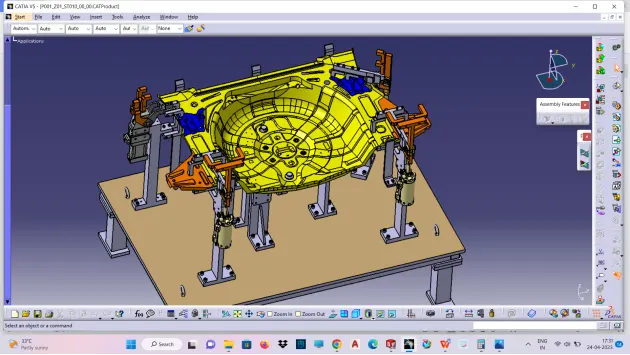
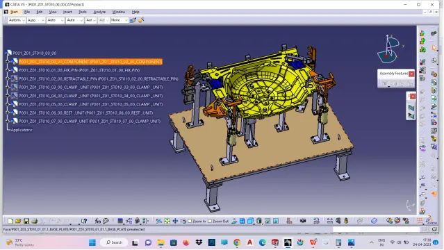
Tree Structure of Fixture Assembly