Week 7 State of charge estimation
1.Simulate the 3 test cases from harness dashboard and write a detailed report on the results
2.What is coulomb counting? Refer to the above model and explain how BMS implements coulomb counting for SOC estimation ?
Solution:
Simulation of closed loop BMS:
The BMS model consists of a BMS ECU and a plant. the control unit with its various monitoting and conr=trol algorithms is connectes to a block with the representation of the battery pack and associated circuitry and peripherals.
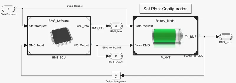
State machine in the BMS ECU defines the main operatung state of the BMS. The state machine has four parallel states
- The first one defines the vairables the variable BMS_ state which indicates standby. Driving, charging, and fault charging comprises constant current and constant voltage stages.
- The ssecond state switches the fault state ON in case a current, voltage, or trmparature value reaches on unsafe level.
- Thirs and fourth states define the contractor ON and OFF switching sequence fro the charger and inverter.
- This is needeed to avoid an excessively large current inrush at the beginning of the charging stage.
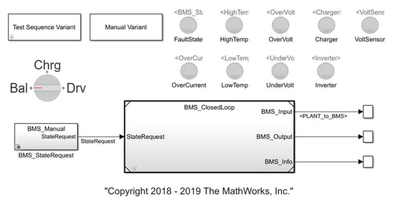
The harness dashboard is used to control and identify the test case states in the state machine. It consists if the tesr sequence variant subsystem which holds three different test cases. This dashboard also helps in determining the fault states and other parameters as shown in the figure . The green color indicates that the system is working without any errors while the red signal will indicate that ther is a fault in the system.
Case:-1: Drive balance-charge balance, there are no errors and faults

When the simulation begins initially the vehicle is in a driving state and the SOC will decrease or this time period. After a time period of 3000 sec, the next step is balancing mode and the vehicle is in standby condition. After another 1000 sec, the vehicle is in the charging phase and the battery's SOC increases almost to 100%. The next phase is the post charging phase in which the vehicle again goes for the stanby mode.
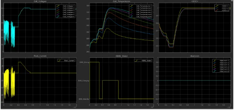
- The inputcycle can be seen in the BMS_state plot in which the vehicle initially undergoes driving, then charging till SOC=90% and then later in the standby state.
- During charging the battery pack voltage is increrased up to 4.2V.
- The cell temparature increases during the driving and charging cycle and starts falling off in stand by mode.
- The SOC drops to less than 50% after driving cycle and then later put into charging until SOC reaches 100%.
- The current supplied to the EV during the driving phase can be seen in the current plot.
Case:-2: Drive-charge, High-Temparature fault

After 10000 sec the driving is over the fault condition occurs and so the SOC doesnot increase even for the charging phase.
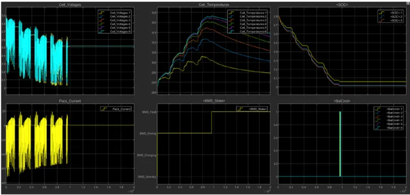
- Cell temparature increases during driving, and since it is higher than recommended, BMS stops the battery from charging, so we can see a gradual decrease in tempararure.
Case:-3: Charging , there is no fault

The SOC increases from 80 to 100% and then remains in standby mode.
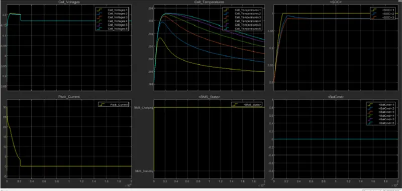
- During charging SOC increases from 80 to 100 %, temparature increases during charging and reduced in the stand by mode of BMS.

Coulumb counting:
Coulumb counting is a technique used to track the state of track of a battery pack. It works by integrating the active flowing current over time to derive the total sum of energy entered and leaving the battery pack. This produce a capacity that is typically measured in amp-hours.
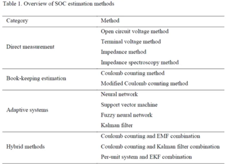
Coulomb counting is a reliable technique to predict remaining battery capacity. A buckboost architecture is advantageous since it regulates Vout when the input is equal to, above or below the output, which maximizes run time when battery-powered. Effectively powering a low-current remote monitoring application can prove very challenging; however, Linear Technology offers a portfolio of leading-edge products capable of very high performance at low power levels. One particular device with nanopower consumption, the LTC3335 buck-boost regulator with integrated coulomb counter and current limiting, makes for an extremely compelling solution for a variety of nonrechargeable, light load applications to save battery run time.
The Coulomb counting method is associated with monitoring the input and the output current continuously. Since capacity is the integral of current with respect to time, by measuring the input and the output current, change in capacity or capacity degradation of a battery can be measured easily.
Limitations of Coulomb's Counting:
Coulomb counting can be very accurate technique, with two limitations.
- Leakage current within a cell doesn't go through the current sensor and is therefore not taken into account.
- The offset in the maesurement of the battery current will result in the SOC drifting up over time.
Coulomb counting is not a preferred method for SOC estimation when a battery must be operated a long time without full charge or discharge. Neverthless, if the initial condition is known and the battery is operated for a relatively short period of time, then this method does provide a reliable measurment. This is important because, in order to design any estimator, a true measurment must be exist for purposes of comparison.
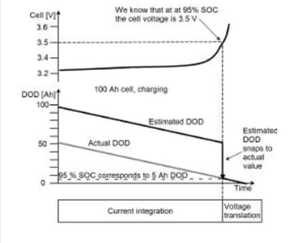
One way of making up for the shortcomings of coulombs counting is to introduce periodic resets to the current integration. Obviously if the battey is fully charged or discharged then a reset should be done. But in vehicel operations batteries are never fuly discharges because that can significally shorten the life of the battery. Also in electrical vehicle and HEV applications, a full xharge never happens because that also asversly affects the life of the battery. Another way to reset the current integration operation to use the batterys open circuit voltage. The fully relaxed OCV of the battery has an approximate one to one relation sho[ with the SOC. However, the relaxed OCV can only be measured when the internal battery chemistry has reached equilibrium.
Coulombs counting works well with Li-ion cells because they have low leakage. Drift remains a major limitation due to the offset in the current sensor, especially Hall effect sensors.
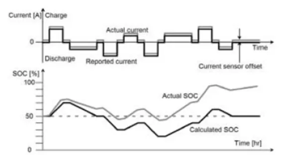
Drifts can become significant in appllications that, for long perios, use very litte battery current or shuttle currentback and forth, in particular.
Standard batteries: Even if the battery is full a small offset in the current sensor in the discharging direction will result in the reported SOC drifting all the way to 0% SOC over time.
HEV Pack: Uses energy from the battery when it needs it, and replenishes it when it can, trying to maintain a 50%SOC.While the reported SOC may very well stay around 50 over time and the actua;l soc will drift due to the small offset in the current sensor. Eventually, the actual battery vharge will approach either the full or the empty state.
Implementation of Coulombs counting in BMS
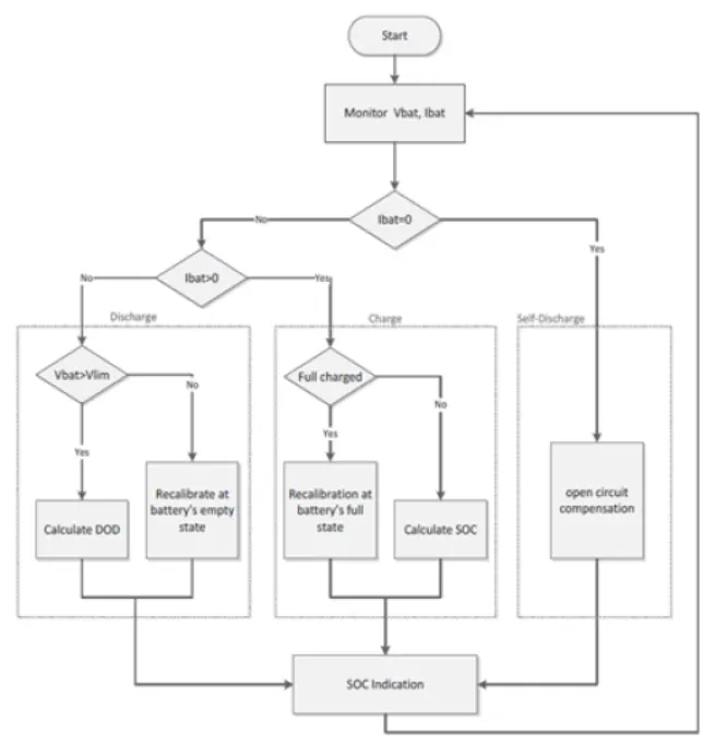
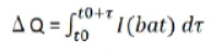
The estimation of the SOC of a Li-ion battery in this method is based on monitoring both the voltage and the current.the operation mode of the battery is recognized by the direction of the current through the battery system, When hte battery is open-circuit flowing through it, and the operating temparture, Coulombs counter Q in an operating period t is obtained by temporal integration of a measured charging/discharging current as
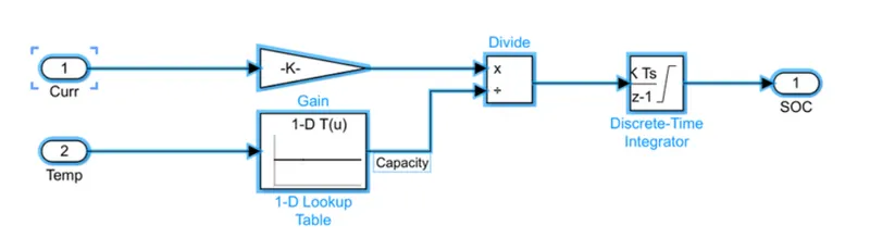
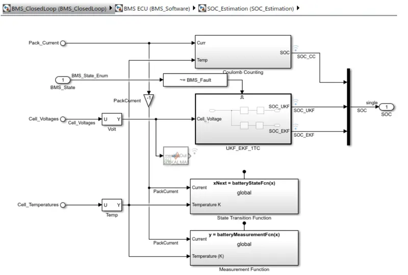
The estimation of the SOC of a Li-ion battery by the developed method is baised on monitoring the voltage, current and temparature. The peration mode of the battery is recognized by the direction of the current through the battery.
Reference:
- Battery managment systems for large lithium battery packs, Andrea Davide
- Implementation of an improved coulomb-counting algorith based on placewise SOC-OCV relatioship for SOC estimation of Li-ion battery, lines baccouche, sabeur jemmali, asma miayah international journal of renewable energy reasearch.