Week-7 Head Impact
WEEK -7 PEDESTRIAN HEAD IMPACT CHALLENGE
AIM :
To simulate a pedestrian head impact test on the given models which are provided for three different cases scenarios and to get the required output data given below for three different cases.
OUTPUT DATA:
- The impact simulation of a simple head impact with the rigid wall.
- The impact simulation of the headform provided with the rigid wall with the stress/ strain plots and acceleration plot.
- The impact simulation of the head form with the hood with the stress/strain plots and accelerations plot. For the hood here aluminum is used.
- The stress/strain plot from the rigid wall simulation has to be compared with the stress/ strain plots from the hood simulation and there should be a detailed explanation if there is any difference in plots.
INPUT DATA :
- For the first case (simple head model), the bonnet should be considered a rigid wall.
- For the second case (Head impact model ), the bonnet should be considered as a rigid wall.
- For the third case, (meshed hood model), the hood is used instead of the rigid wall and elastoplastic material aluminum is used for the hood.
- The files have to be organized using a multi-include file model using, the keywords *INCLUDE,*INCLUDE_TRANSFORM,*DEFINE_TRANSFORMATION.
- The impact angle of the pedestrian head is between 35-75 degrees.
- The HIC must be calculated manually with the help of LS-PRE POST.
PROCEDURE: (SIMPLE HEAD MODEL )
- The simple _head_Model.k file is opened using LS- prepost.
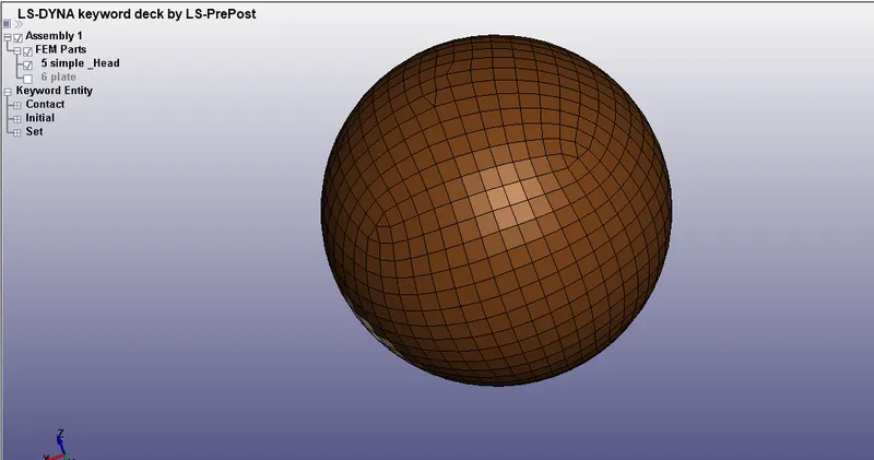
Fig, represents the simple head model opened in LS-PREPOST
- Then, the rigid wall is created by using the 4N-SHELL node option.
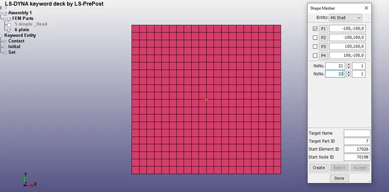
Fig, represents the creation of a rigid wall, by using the 4N shell option.
- After, creating the rigid wall, the head is translated by using transform option.
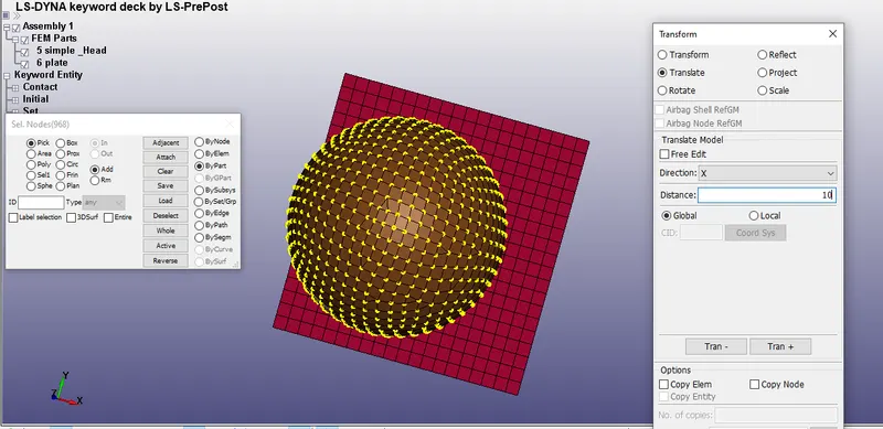
Fig, represents the translation of head with respect to the rigid wall
- Then, the section for the rigid wall is defined by using a shell section.
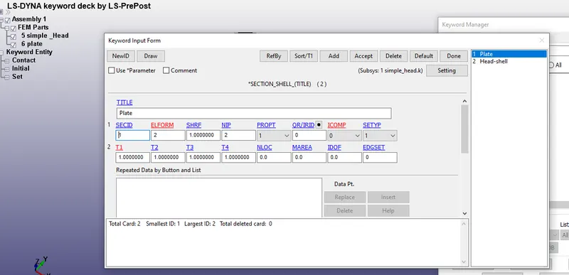
Fig, represents the section shell defined for the rigid wall.
- The head and the rigid wall have the shell section since both of them have a shell mesh.
- Then, the material properties for steel have been assigned to the rigid wall by using keyword manager →MAT→020 Rigidwall.
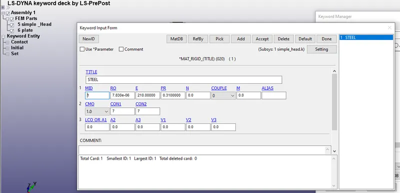
Fig, represents the selection of the rigid wall material and the properties of steel has been assigned to it.
- Then, for the head material the elastic material properties are assigned and here the material properties of the aluminium are assigned to it.
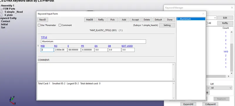
- Fig, represents the assignment of material properties of aluminum to the elastic material
- Then, we go to the part and assign the section and material properties to the simple head and the rigid wall.
- The material properties and section properties for both parts are assigned successfully.
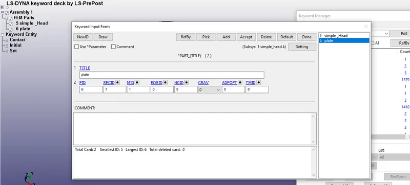
Fig, represents the assignment of SECID and MID for both the parts.
- After, that we need to assign the contacts in order to capture the interactions of the simple head with the rigid wall.
- In this case, an automatic surface to surface contact is used to define the contacts.
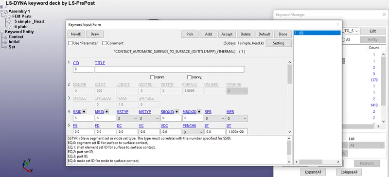
Fig, represents the automatic surface contact used for this case.
- The part Id for both the slave and Master are defined. For the Master, the part id of the Rigid wall is defined and for the slave part, the part ID of the simple head is defined.
- once, everything is done an NSET id is created by using create entity option to define the velocity for the head.
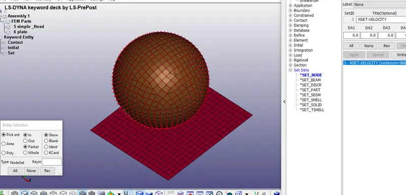
Fig, represents the creation of NSET to define the velocity.
- Here, for the pedestrian impact test, we have considered that the velocity of 40 Km/hr which we converted to 11.11 mm/ms to our unit system.
- Then, we assign the velocity by using the initial velocity card and we assign the velocity in the VZ direction which is in the Z direction.
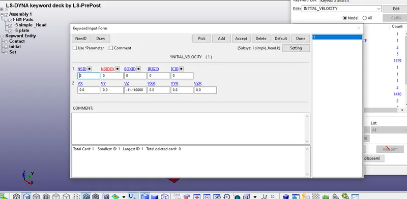
Fig, represents the assignment of velocity (-11.11 mm/ms )in the VZ direction
- once, everything is done in the keyword manager we request here in the database, we request for our required output such as ASCII option, Binary D3 plot, and extend binary plot
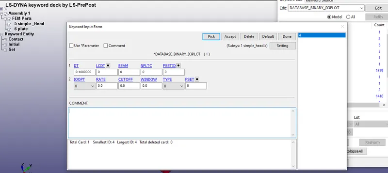
Fig, represents the time step dt is assigned for the Database_Binary_D3 plot.
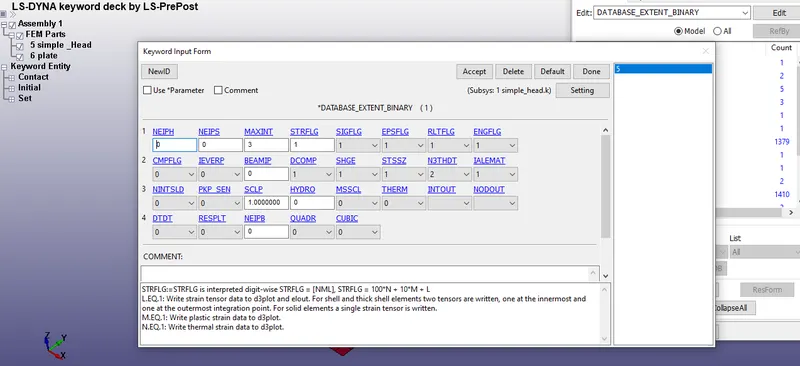
Fig, represents the assignment of STRFLG for requesting plastic strain in the output using Database_Extend _ binary
- Then, the final thing is to define the termination time of the simulation and this can be done by calculating the ratio of distance / velocity
- The distance between the head and the rigid wall is around 37 mm and the velocity is -11.11 mm/ms.
Time = Distance / velocity
T = 3.33 mm/ms
- We provide an extra time around 6 ms to see the bouncing back of the head and to see what is happening after the impact.
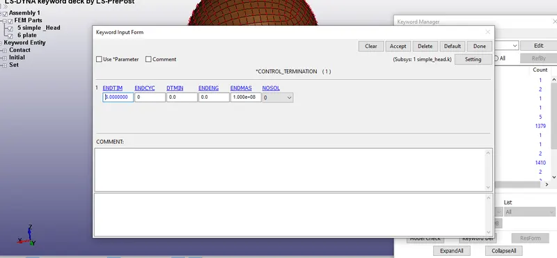
Fig, represents the termination time provided in the control_Terimination card.
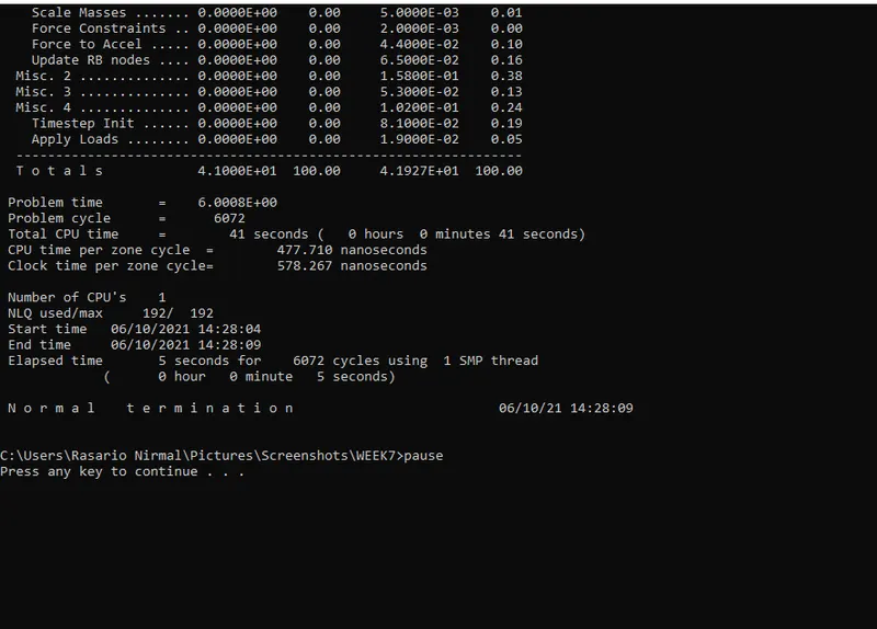
Fig, represents the Normal termination of the simple head simulation.
OUTPUT
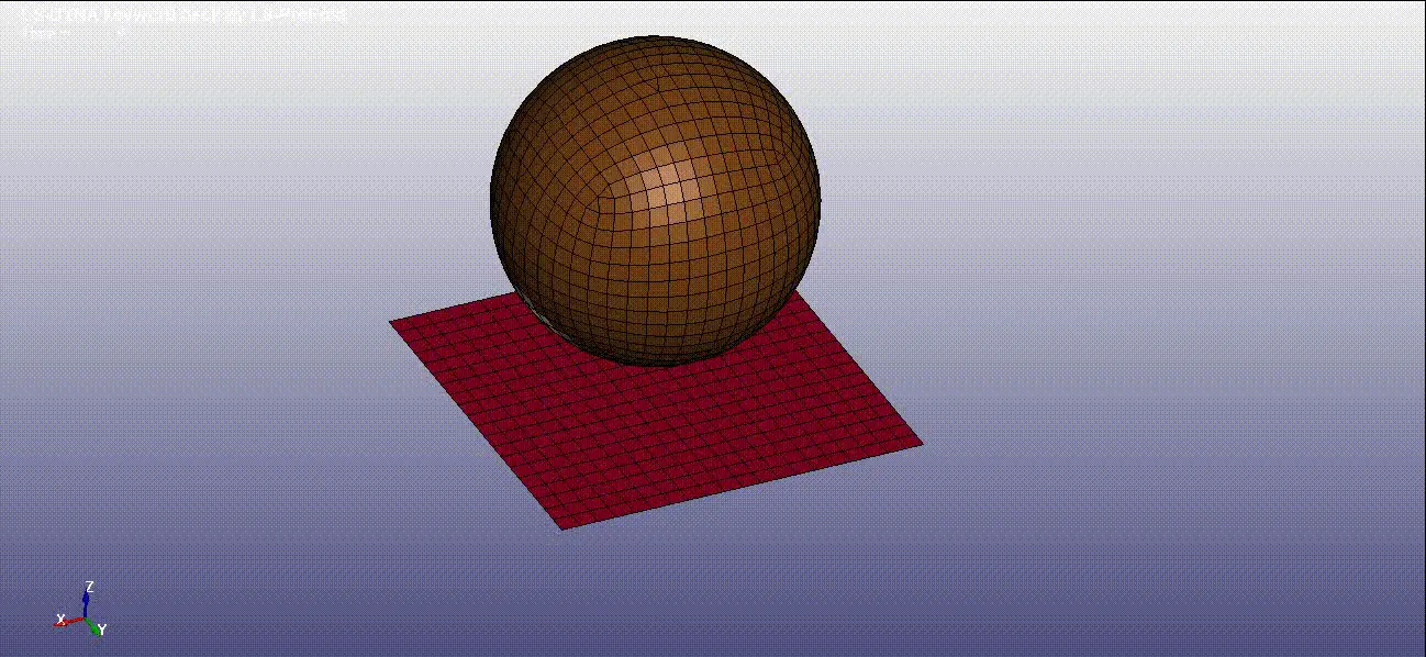
Fig, represents the impact of the simple head simulation with the rigid wall
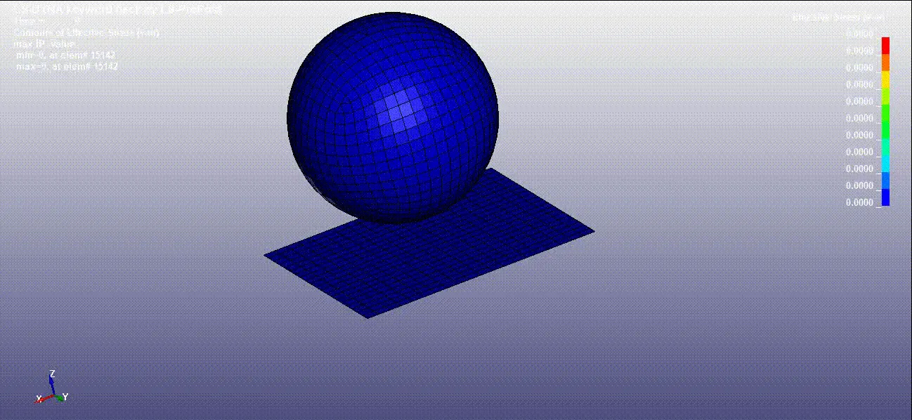
Fig, represents the Von-mises stress generated in the rigid wall while the simple head is impacted on the rigid wall.
PROCEDURE (CASE 2)
- A pedestrian head impact file is downloaded, firstly, and then a new .k file is created in the LS prepost.
- Then, in the .k file, by using *Define transformation, the head form of the model is oriented at an angle of 37 degrees with respect to the x-axis.
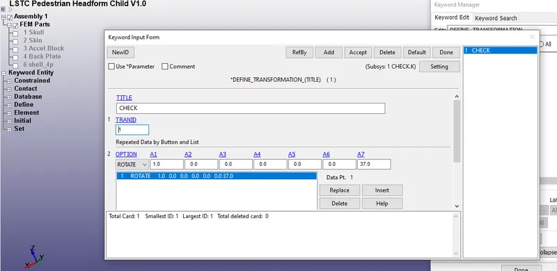
Fig, represents the assignment of *Define transformation in the card.
- The head is orientated with respect to the x-axis and TRANID is assigned in the *Define transformation card.
- Then, in the keyword manager → include →transform , by using the include transform the file of Pedestrian head form is included in the newly created .k file .
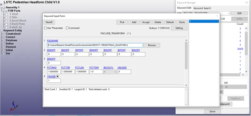
Fig, represents the Pedestrian head form is been included using *Include transform
- After including the file it's been saved and it is opened in LS-PRE POST.
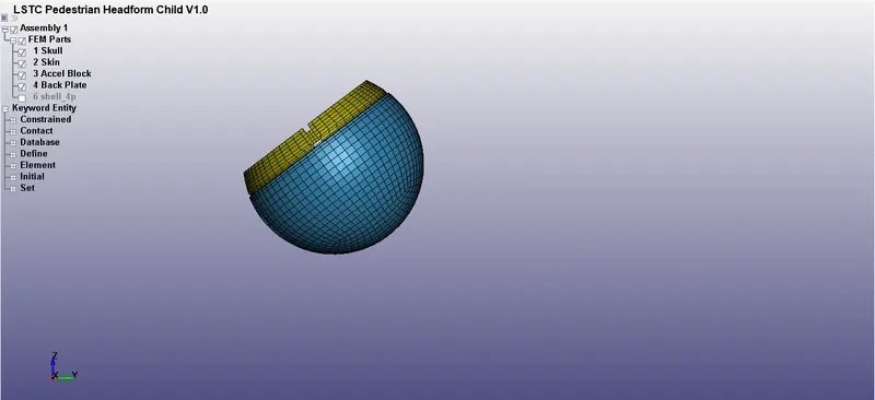
Fig, represents the orientation of head form in the new file.
- Then, the rigid wall is created by using the 4N-SHELL node option.
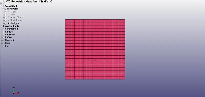
Fig, represents the rigid wall creation using 4N shell
- After, creating the rigid wall, the head is translated by using the transform option.
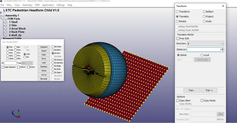
Fig, represents the translation of rigid wall with respect to the head
- Then, the section for the rigid wall is defined by using a shell section.
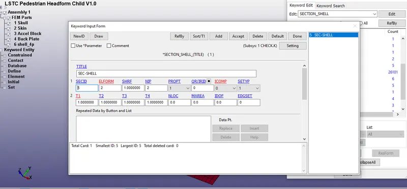
Fig, represents the section shell defined for the rigid wall.
- The head and the rigid wall have a different section, for the rigid wall it's a shell section and it involves the assignment of thickness and the head is defined by a solid section.
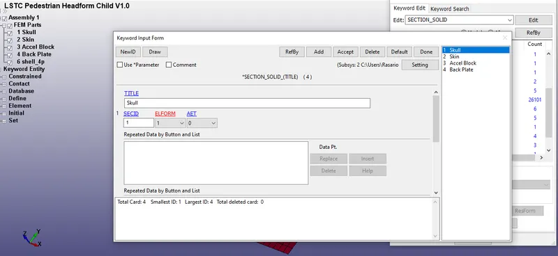
Fig, represents the section solid which is predefined in the included pedestrian headform model.
- Then, the material properties for steel have been assigned to the rigid wall by using keyword manager →MAT→020 Rigidwall.
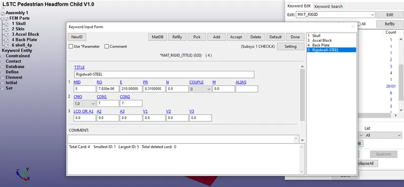
Fig, represents the selection of the rigid wall material and the properties of steel has been assigned to it.
- Then, the material properties of the head are predefined in the included headform model.
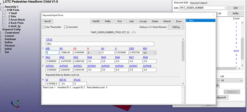
Fig, represents the predefined material assigned to the included headform model
- Then, we go to the part and assign the section and material properties to the included head form model and to the rigid wall.
- The material properties and section properties for both parts are assigned successfully.
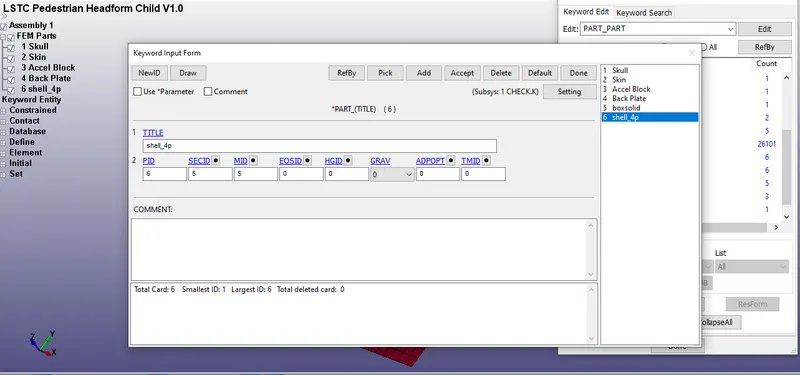
Fig, represents the assignment of MATID and SECID to the rigid wall.
- The sec Id and MAT Id for the head form file are been predefined and we don't need to define them.
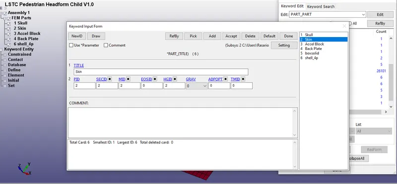
Fig, represents the predefined MATID AND SECID for the headform model.
- After, that we need to assign the contacts in order to capture the interactions of the pedestrian head form with the rigid wall.
- In this case, an automatic surface to surface contact is used to define the contacts.
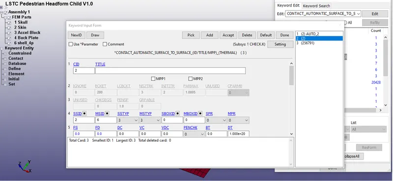
Fig, represents the Automatic surface contact is assigned to the skin and to the rigid wall by using part ID's
- The part ID of the skin is assigned to the SSID and the part ID of the rigid wall is assigned to the MSID.
- once, everything is done an NSET id is created by using create entity option to define the velocity for the head.
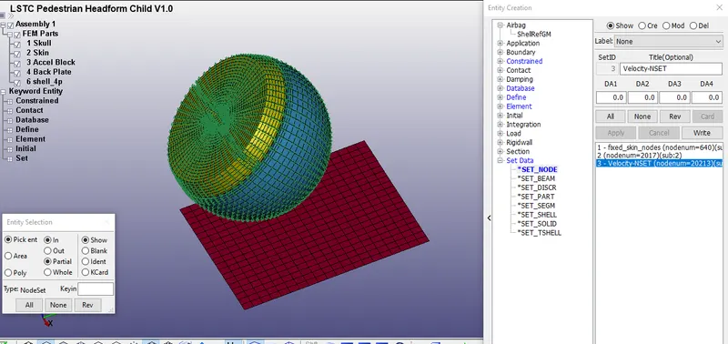
Fig, represents the creation of NSET for defining the velocity for the head.
- Here, for the pimpact test, we have considered that the velocity of 40 Km/hr which we converted to 11.11 mm/ms to our unit system.
- Then, we assign the velocity by using the initial velocity card and we assign the velocity in the VZ direction which is in the Z direction.
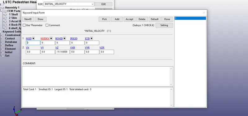
Fig, represents the assignment of velocity (-11.11 mm/ms )in the VZ direction
- once, everything is done in the keyword manager we request here in the database, we request for our required output such as ASCII option, Binary D3 plot, and extend the binary plot
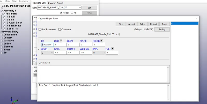
Fig, represents the time step dt is assigned for the Database_Binary_D3 plot.
- The database_Binary_D3plot is defined to get the output animation process.
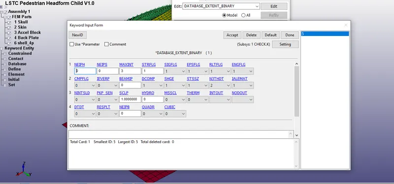
Fig, represents the assignment of STR to get the plastic strain data in the *Database_Extend_Binary.
- Then, the final thing is to define the termination time of the simulation and this can be done by calculating the ratio of distance/velocity
- The distance between the head and the rigid wall is around 52 mm and the velocity is -11.11 mm/ms.
Time = Distance / velocity
T = 4.68 mm/ms
- We provide an extra time around 7 ms to see the bouncing back of the head and to see what is happening after the impact.
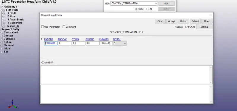
Fig, represents the assignment of termination time.
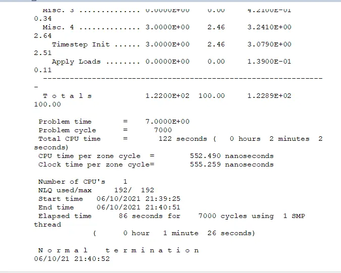
Fig, represents the normal termination of the problem.
RESULTS
OUTPUT (CASE2)
EFFECTIVE STRESS
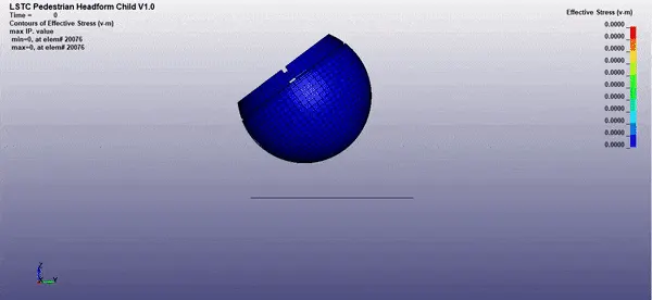
Fig, represents the effective stress of the head during impact
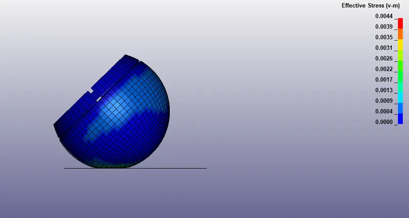
Fig, represents the effective stress of the head under static.
- From, the figure it has been observed that the maximum effective stress of the head was found to be 0.0044 Gpa and it was also observed that there is no stress observed on the rigid wall since it is a rigid member and all the stress were found to be on the head. We conclude that if a head hits on the rigid member the stress on the head would be higher since the rigid wall cannot plastic deform or takes the impact load and so the possibility of a head injury would be high.
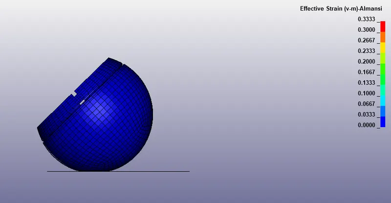
Fig, represents the effective strain developed on the headform model
- From, the figure it is observed that the maximum effective strain during the impact was found to be 0.3333 since the rigid wall doesn't take up any load during impact the impact was found to be higher.
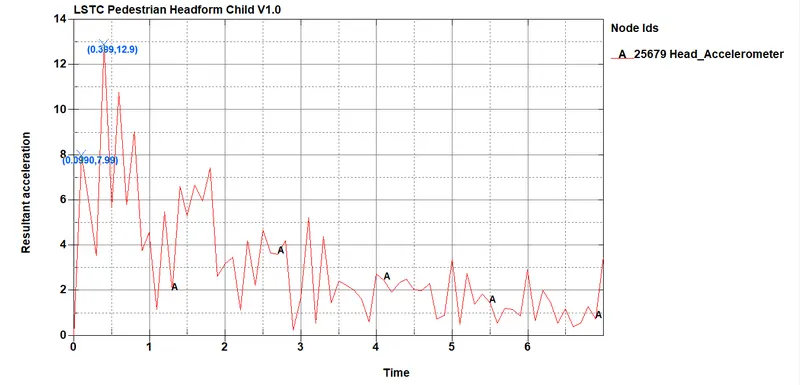
Fig, represents the acceleration plot of the head form model.
- From, the figure it has been observed that the acceleration of the head was increasing till 8 mm/ms^2 and after the impact the head starts to deaccelerate and during the rebounce the acceleration and deceleration happen until the termination time.
MESHED HOOD MODEL (CASE-3 )
PROCEDURE:
- The meshed hood.k file is initially open in the LS - prespost.
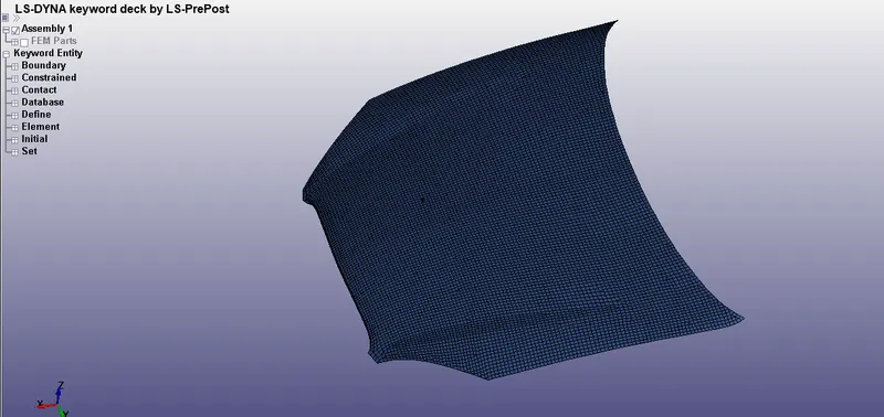
Fig, represents the meshed hood model.
- Then, in the .k file, by using *Define transformation, the head form of the model is oriented at an angle of 37 degrees with respect to the y-axis.
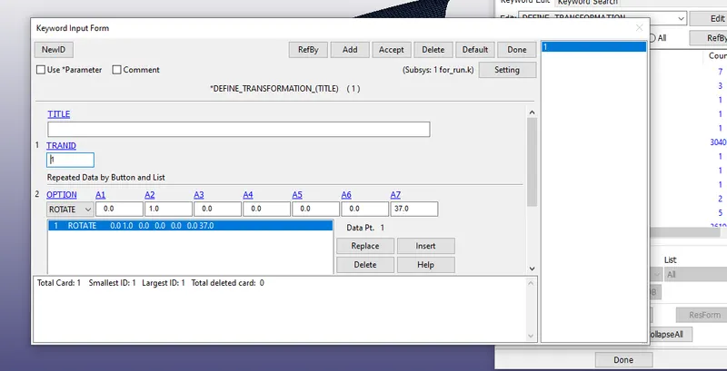
Fig, represents the assignment of *Define transformation in the card.
- The head is orientated with respect to the Y-axis and TRANID is assigned in the *Define transformation card.
- Then, in the keyword manager → include →transform , by using the include transform the file of Pedestrian head form is included in the meshed hood file.
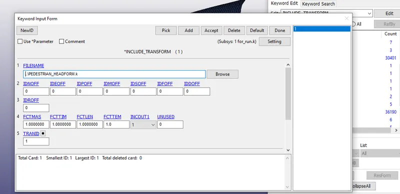
Fig, represents the Pedestrian head form is been included using *Include transform
- After including the file it's been saved and it is opened in LS-PRE POST.
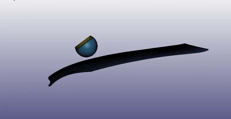
Fig, represents the orientation of the head towards the meshed hood model.
- Then, the section for the rigid wall is defined by using a shell section.
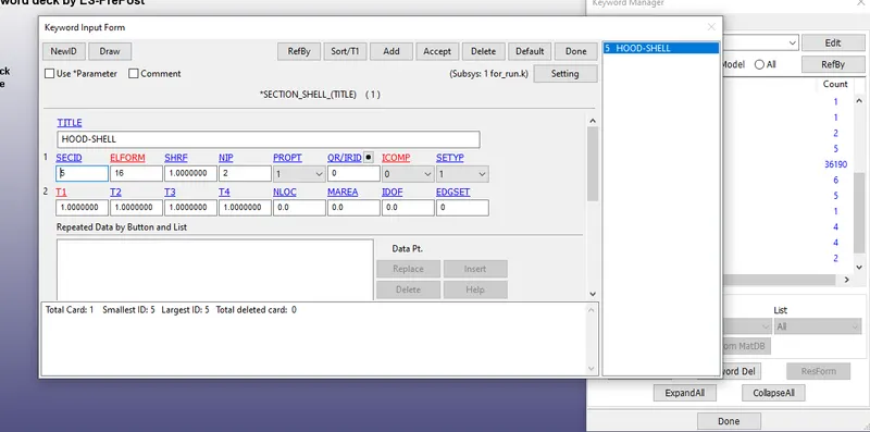
Fig, represents the assignment of the section to the hood
- For the head, the section solid is already predefined.
- Then, the material properties for steel have been assigned to the hood by using keyword manager →MAT→024 *MAT_PIECEWISE_LINEAR_PLASTICITY
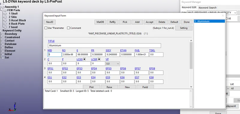
Fig, represents the assignment of aluminium properties to the hood.
- Then, we go to the part and assign the section and material properties to the included head form model and to the meshed hood model.
- The material properties and section properties for both parts are assigned successfully.
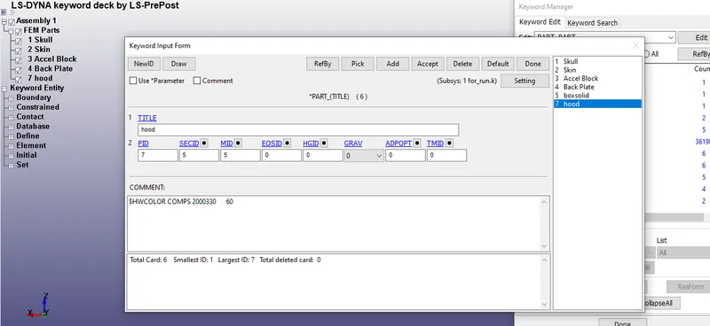
Fig, represents the assignment of SECID and MID for the hood part
- For the headform model, containing the parts, the SECID and MATID are predefined in the model.
- Then, the boundary conditions are given or defined to the model, the outer edges of the hood are constrained in all directions.
- This is done by selecting all the edges which contain nodes in the hood.
- A node-set is created by selecting all the edges in create entity → boundary →spc card
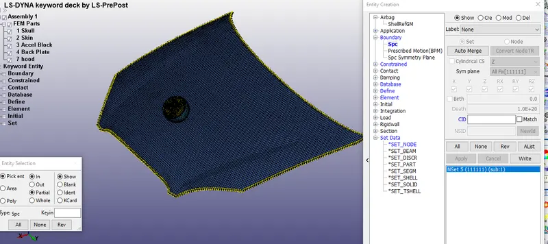
Fig, represents the outer edges that are constrained in the hood model.
- All the DOF'S are constrained at the outer edges of the model.
- Then, a node-set id is created for defining the velocity, before that a velocity for the head impact is resolved into horizontal and verticalcomponents to get the resultant velocity .
- Here we take the initial velocity as 40km/hr which is converted to our unit system as -11.11 mm/ms and when it is resolved into vx = -8.8699 and Vz= -6.67 mm/ms
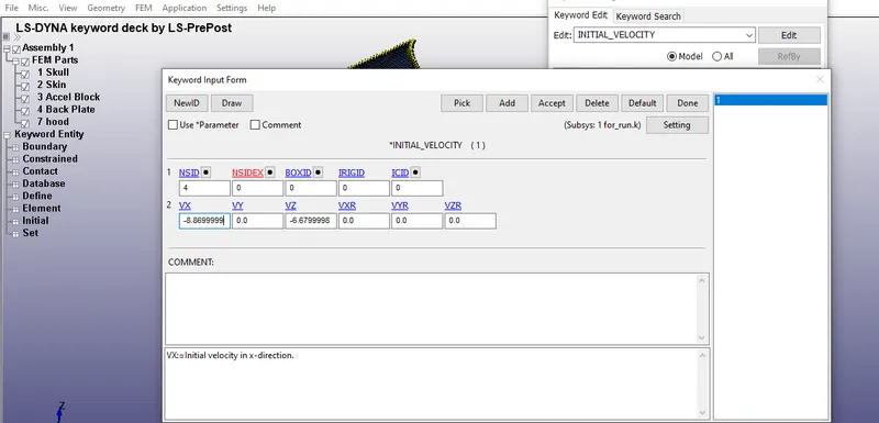
Fig, represents the assignment of resolved velocities to the initial velocity card
- once , the assignment of velocity is done and we need to assign the contacts and in this case an automatic surface-to-surface contact is used.
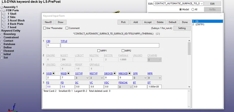
Fig,represents the assigment of MSID and SSID to the automatic surface to surface contact
- In this case , the hood part Id is given as MSID and the head is given as SSID
- Then , the necessary outputs such as ASCII output , Extend binary and Binary D3 plots are defined.
- Finally, the terimination time is defined in the control terimination card.
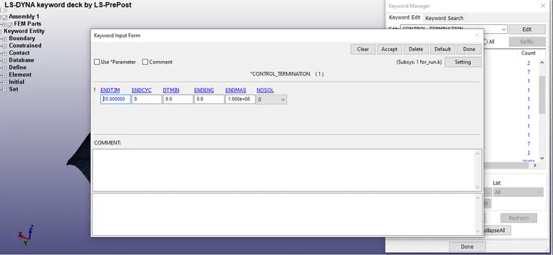
Fig, represents the termination time given to the control termination card.
- Here, we give the termination around 35 ms in the control termination card.
- Once, everything is done the file is opened in LS run and the file is run to execute the problem.
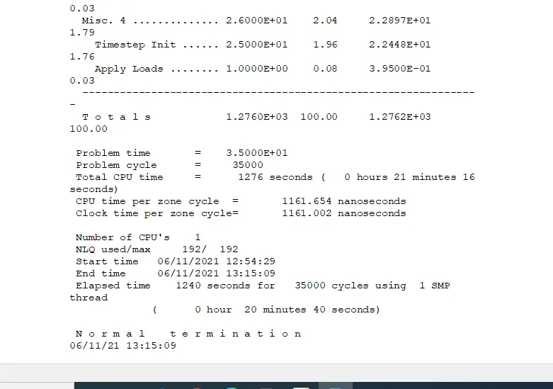
Fig, represents the normal termination of the problem using the LS-RUN.
- From, the figure it is seen that the normal termination of the problem takes 20 minutes & 40 secs for the execution or for the termination since the end time is given as 35 ms and so it takes a long time for the execution.
RESULTS
OUTPUT
ANIMATION OF EFFECTIVE STRESS OF THE HOOD
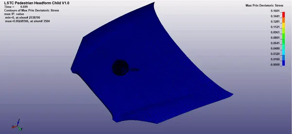
Fig, represents the von-mises stress of the hood
- From, the animation it is clear that the von-mises stress increases in the hood when the head is getting impacted on it for every time interval.
VON-MISES STRESS OF THE HOOD (STATIC)
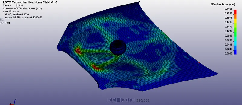
Fig, represents the von-mises stress of the hood on the static condition.
- From, the figure it is clear that the von-mises stress was found to be maximum around 0.2464 Gpa during the impact of the head on the hood and the von-mises stress are getting increased because of taking the impact load of the head and the material is elasto-plastic , so the hood material is subjected to von-mises stress. In case of the rigid wall , the von-mises stress was found to be zero, since the wall is rigid in nature.
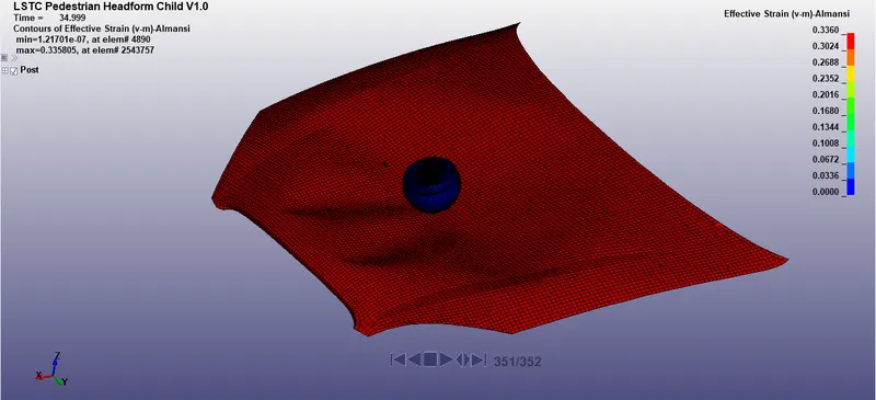
Fig, represents the effective strain of the hood.
- From, the figure it is clear that the effective strain of the hood is increased because of the impact load on the hood. The hood material is made up of aluminum and since it is elastoplastic in nature, the material deforms slightly due to the impacted load (head ). The hood takes some strain and provide lesser injury to the head. In the industry, the hood is made up elasto-plastic material where it deforms and takes some strain to provide less injury to the head. on, the other hand there is no-strain occurs in the rigid wall when the head is getting impacted on the rigid wall. In such a case, there is a high risk of head injury since there is no load absorption or no plastic deformation of the rigid wall. In such cases, the injury would be severe.
ACCELERATION PLOT OF THE HEAD
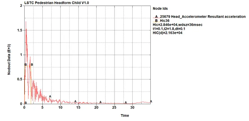
Fig, represents the acceleration plot by using a head accelerometer
- From, the figure it is seen that the acceleration plot of the head can be obtained by the head accelerometer and we see the head is getting accelerated and after the impact, the deacceleration of the hood drastically reduces up to the termination time. This is due to the increase of mass increases the forces and with a higher momentum when the head is getting impacted, the hood takes some impact energy and after that deacceleration of the head takes place. This is due to the increase in momentum.
HIC 36 plot
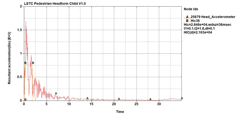
Fig, represents the HIC-36 plot of the head by using a Head accelerometer
- From, the graph it is clear that the HIC lasts for a shorter interval of time (t=0.1 to 1.8), indicating that the acceleration and deacceleration last for an only shorter interval and also tells that the head injury would be less since the acceleration and deacceleration last for a shorter period of time.
COMPARISON OF STRESS / STRAIN PLOTS OF RIGID WALL WITH THE HOOD WALL
- CASE 2 (RIGIDWALL): In the case of the rigid wall, the stress is getting increased in the head, since the rigid wall is not taking the load and corresponding stress and strains are getting increased in the head since the wall is rigid. Also, we notice that the strain develops on the head indicates that the probability of head injury occurring in the head is high. The stress value is found to be 0.0044 Gpa and the strain is found to be 0.33
- CASE3:In, the case of the meshed hood, the meshed hood is taking all the stress & strains, indicating that the hood takes the load when the head is getting impact. The hood takes the load since the material of the hood is made up of elastoplastic material. The material takes the impacted head and deforms the hood. Here as we observe the effective stress on the hood was to be 0.2464Gpa and the effective strain of the hood is found to be 0.33. We can clearly see that the hood is taking the load and the head getting stressed is less. The probability of head injury is less since the hood is taking the impacted load.
DIFFERENCES IN STRESS / STRAIN PLOTS FOR BOTH THE CASES
case 2: For case 2, the head is getting stressed and there is no deformation in the rigid wall. The stress and strains are found to be on the head. The probability of head injury is high for case 2 since the rigid wall doesn't take the load.
case 3: For case 3, the hood is getting stressed and there is a deformation that occurs in the hood and not on the head. The probability of head injury is less since the hood takes the load (head). The stress and strains are found on the hood.
CONCLUSION
- Thus, the head impact test is simulated for three different cases and the results are obtained.
- The stress/strain plots of the rigid wall simulation have been successfully compared with the rigid wall and the differences are spotted.
- The Hic 36 and acceleration plot for the meshed hood is been plotted successfully.
- Thus, the goal of the project is successfully accomplished and output data are successfully obtained.