Week 7: Gearbox simulation
Part 1:
- 20% Immersion, Fluid - Engine oil.
- 30% Immersion, Fluid- Engine oil.
- 20% Immersion,Fluid-n-heptane (c7h16).
- 30% Immersion,Fluid-n-heptane (c7h16).
Part 2:
- What is Dynamic meshing? Give some other examples where dynamic meshing can be used.
- What is the fluid Sloshing effect? Discuss whether the sloshing effect is good or bad? Explain.
- What is the use of UDF?
- Discuss the common errors that occurred in the simulation. A] 'Dynamic mesh failed' error. B] 'Negative cell volume detected' error.
Your Answers
Aim: To perform simulation of fluid sloshing effect inside a Gearbox.
Introduction:
A gearbox is a mechanical device utilized to increase the output torque or change the speed (RPM) of a motor. The motor's shaft is attached to one end of the gearbox and through the internal configuration of gears of a gearbox, provides a given output torque and speed determined by the gear ratio.
The physical components of gearboxes vary from one gearbox type to another, as well as differences between manufacturers. Most gearboxes are constructed from steel materials such as iron, aluminium and brass. Unlike other gearbox types, spur gearboxes can also be made with plastics such as polycarbonate or nylon. Here in our project gearbox is constructed from aluminium. Other than the raw materials used, the orientation of the gear teeth plays a major role in the overall efficiency, torque and speed of the system. Straight gear teeth gearboxes are typically used in low-speed applications. These gearboxes can be noisy and may have lower overall efficiency. Helical gearboxes are typically used in high-speed applications. These gearboxes are quieter in operation than straight gear teeth gearboxes, which may improve their overall efficiency.
Types of Gearboxes:
Bevel gearbox:
There are two types of bevel gearboxes which include either straight or spiral teeth gears. Straight bevel gears have straight and tapered teeth and are used in applications requiring slow speeds. Spiral bevel gears have curved and oblique teeth and are used in applications requiring high-performance, high-speed applications.
Helical gearbox:
Helical gears are cut at angles which allow for gradual contact between each of the helical gear teeth. This type of innovation provides for a smooth and quiet operation. Gearboxes using helical gears are applicable in high horsepower and efficient applications.
Spur gearbox:
Spur gears are made with straight teeth mounted on a parallel shaft. The noise level of spur gears is relatively high due to colliding teeth of the gears which make spur gear teeth prone to wear. Spur gears come in a range of sizes and gear ratios to meet applications requiring a certain speed or torque output.
Worm gearbox:
Worm gears are able to withstand high shock loads, low in noise level and maintenance-free but are less efficient than other gear types. Worm gears can be used in the right-angle configuration. The worm gearbox configuration allows the worm to turn the gear with ease; however, the gear cannot turn the worm. The prevention of the gear to move the worm can be used as a braking system. When the worm gearbox is not active, it is held in a locked position.
Planetary gearbox:
Planetary gearboxes are named so due to their resemblance to the solar system. The components of a planetary gearbox include a sun gear, ring gear and planetary gears. The sun gear is the central gear which is fixed in the centre, ring gear (annulus ring) which is the outer ring with inward-facing teeth, and the planetary gears which rotate around the sun gears and mesh with both the sun and ring gear.
Lubrication:
Gearboxes rely on lubrication to reduce friction and provide cooling for optimal operation and life. Gearbox manufacturers provide recommendations for the type of lubrication to be used and the typical lubrication intervals, but the actual gearbox lubrication requirements depend on the environmental conditions the gearbox is exposed to, whether it is properly maintained, and whether it experiences overloading.
There are several methods of lubricating a gearbox, few of them are mentioned below
- Grease lubrication
- Oil splash lubrication
- Forced oil lubrication
Oil splash lubrication:
Oil splash lubrication is often used for helical, spur, and bevel gearboxes. This method is also referred to as an oil bath because it uses a reservoir is filled (or partially filled) with oil. As the gears rotate, they dip into this oil bath and splash the oil onto the other gears and bearings. But if the gear teeth are fully submerged, a condition is known as “churning” occurs.
The effectiveness of oil splash lubrication is heavily dependent on the speed of the gears. A common rule of thumb is that a tangential speed of at least 3 m/s is required in order for splash lubrication to be effective.
Objective:
The objective of this project is to perform simulation of fluid sloshing effect inside a gearbox, to understand and implement the dynamic meshing option and optimize it to obtain an accurate result, to use the UDF to define the motion of the gear in pair, to compare the cases with two different lubricants by varying the immersion volume.
Geometry:
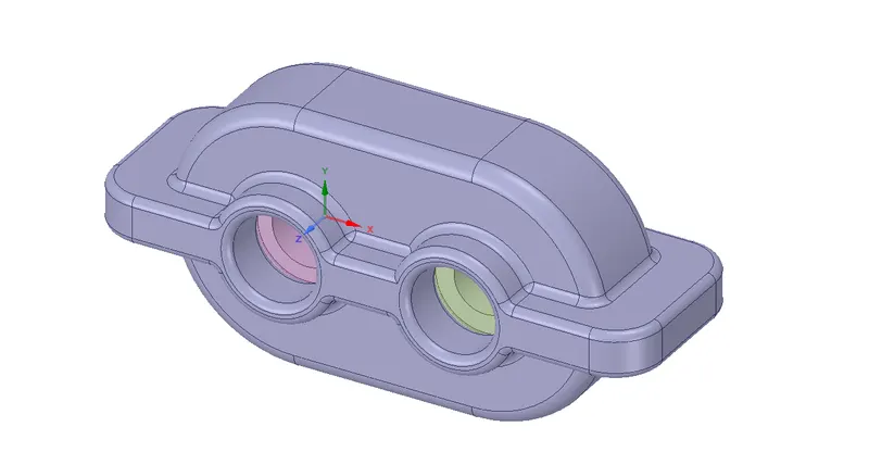
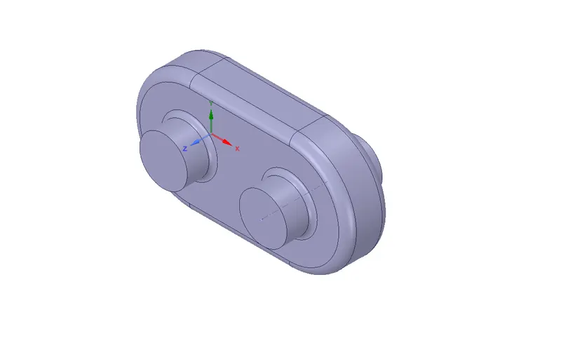
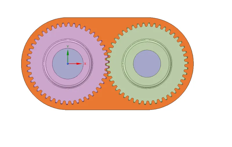
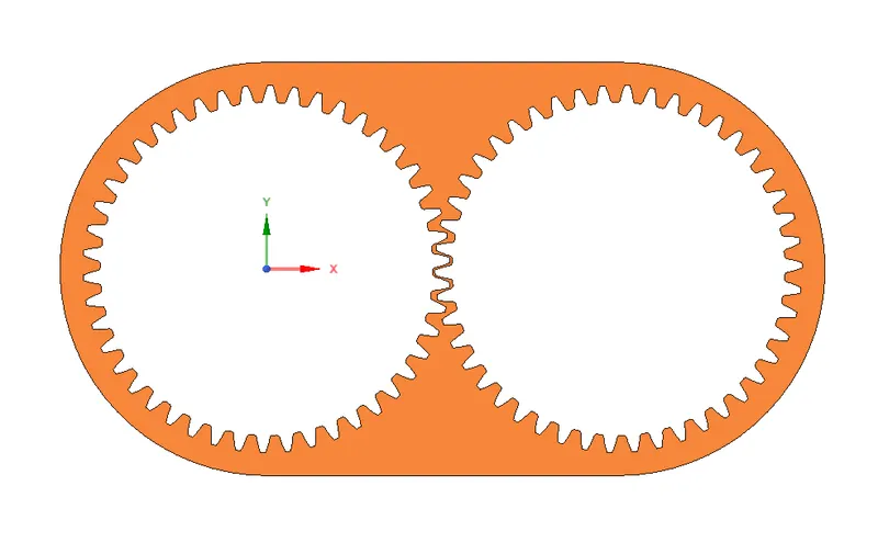
The 3D model of the gearbox is imported to Spaceclaim. Extraction of fluid volume is done by volume extraction. Once the extraction of the volume is done, the body is split into half in order to extract the 2D geometry in the middle plane. This is done by selecting the fluid domain and copy-pasting it to the new design. Share topology is set to share.
3D Model
Fluid volume
Sectional view
2D geometry
Mesh:
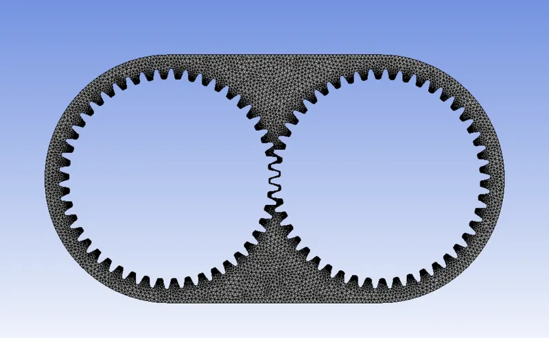
Triangle meshing method is assigned. Element size of the mesh is 2mm. Capture proximity is enabled. The number of cells across the gap is given as 3. The naming of left and right set of gear teeth is done so that while importing the UDF we can give a left motion to the left set of gears and right motion to the right set of gears.
Number of elements = 17731
Number of nodes = 10408
Mesh metric:
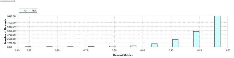
The mesh metric that identifies the elements according to their quality was employed and it can be seen that the elements of lowest quality are minimal, most of the elements have very high quality in the range of 0.9-1.
Setup:
Solver Type – Pressure based
Time – Transient
Gravitational acceleration (Y )= -9.81
Models - Multiphase – Volume of fluid – Implicit formulation
Viscous model – K-epsilon Realizable with enhanced wall treatment.
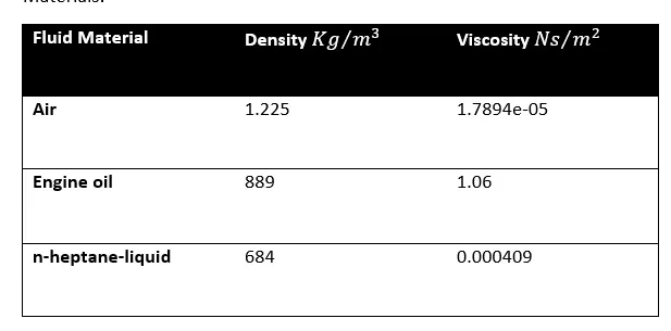
Materials and its properties:
Dynamic meshing:
Mesh methods:
Smoothing: Diffusion
Remeshing: Local cell
Minimum length scale: 0.0001
Maximum length scale: 0.0033
Maximum cell skewness: 0.5
Size re-meshing interval: 0
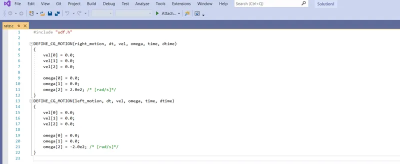
The motion is assigned using User-defined function and centre of gravity location for both the gears were mentioned i.e. (0,0) and (0.115,0).
Primary phase – air
Secondary phase – Engine oil or n-heptane-liquid
Initialization method – Hybrid
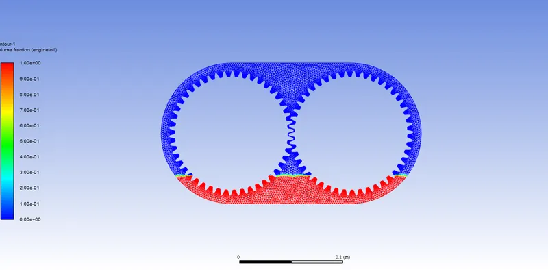
Mark/Adapt cell: Using mark option we have to define the fluid region
For 20% immersion:
Xmin = -0.054m Xmax = 0.169m
Ymin = -0.0405m Ymax = -0.0675m
For 30% immersion:
Xmin = -0.06183m Xmax = 0.17683m
Ymin = -0.027m Ymax = -0.0675m
Once the marking is done, we have to patch it.
Phase - Engine oil/ n-heptane-liquid
Variable – volume fraction
For engine oil/n-heptane-liquid we shall give a value 1 so that automatically the air will take the value 0.
20% immersion:
30% immersion:
Here we will take angular velocity w = 200 rad/s
But w =(2*3.14*N)/60 --------(1)
From equation 1 we can find N
N =31.83 rps
By cross multiplication method, we can find the time required to complete one full rotation and it was found out to be 0.0314s.
So, in order to complete minimum of 2 rotations we need N = 2*0.0314s = 0.0628s.
From the available data, we can find the number of time steps, it can be found out using the formula mentioned below.
Time step size * number of time steps = Total flow time
Let us take time step size to be 0.0001
We get,
0.0001* Number of time step = 0.0628
Therefore, the number of time step = 628
We shall take the number of time step as 700.
Results:
Case 1: 20% Immersion, Fluid - Engine oil.
Case 2: 30% Immersion, Fluid - Engine oil.
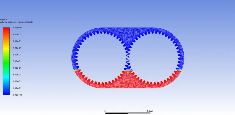
Case 3: 20% Immersion, Fluid - n-heptane-liquid.
Case 4: 30% Immersion, Fluid - n-heptane-liquid.
Case 1:
Residuals:
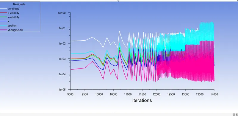
Contour at 0.07 flow time :
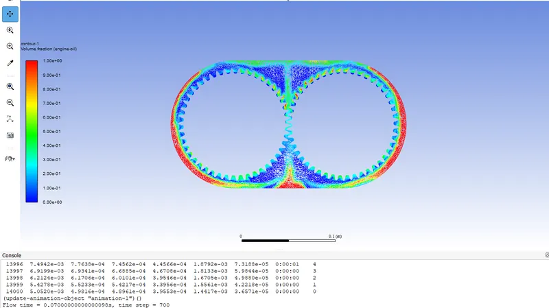
Animation:
Case 2:
Residuals:
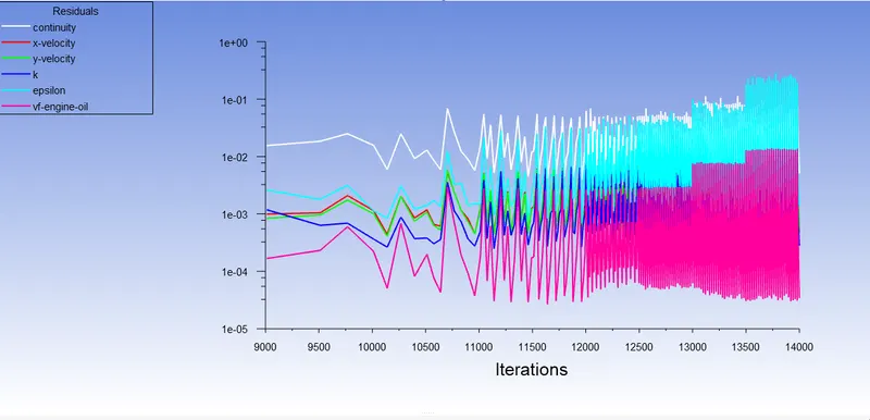
Contour at 0.07 flow time :
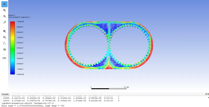
Animation:
Case 3:
Residuals:
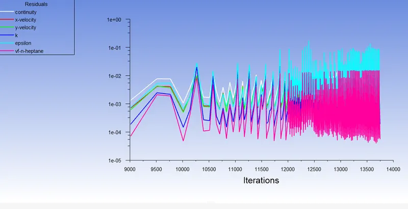
Contour at 0.07 flow time :
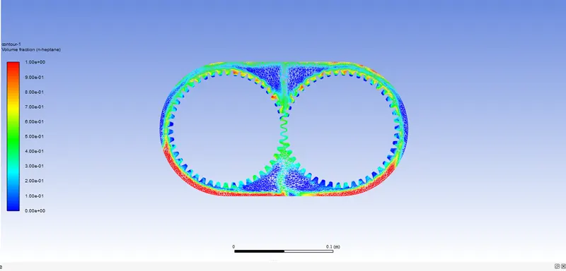
Animation:
Case 4:
Residuals
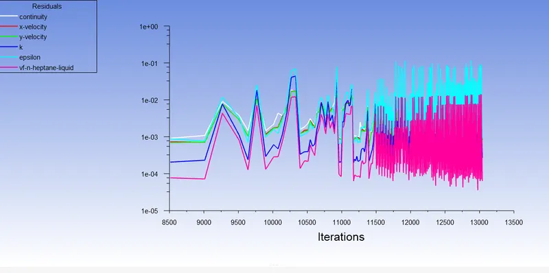
Contour at 0.07 flow time :
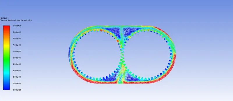
Animation:
Dynamic Meshing:
The dynamic mesh model allows us to move the boundaries of a cell zone relative to other boundaries of the zone, and to adjust the mesh accordingly. The boundaries can move rigidly with respect to each other (that is, linear or rotational motion), and/or deform. The motion of the boundaries can be rigid, such as pistons moving inside an engine cylinder or a flap deflecting on an aircraft wing, or deforming, such as the elastic wall of a balloon during inflation or a flexible artery wall responding to the pressure pulse from the heart. In either case, the nodes that define the cells in the domain must be updated as a function of time, and hence the dynamic mesh solutions are inherently unsteady. An important special case of dynamic mesh motion is called the sliding mesh in which all of the boundaries and the cells of a given mesh zone move together in a rigid-body motion. In this situation, the nodes of the mesh move in space (relative to the fixed, global coordinates), but the cells defined by the nodes do not deform. Furthermore, mesh zones moving adjacent to one another can be linked across one or more non-conformal interfaces. As long as the interfaces stay in contact with one another (that is, “slide” along a common overlap boundary at the interface), the non-conformal interfaces can be dynamically updated as the meshes move, and fluid can pass from one zone to the other. The dynamic mesh model in ANSYS Fluent can be used to model flows where the shape of the domain is changing with time due to motion on the domain boundaries. The dynamic mesh model can be applied to single or multiphase flows (and multi-species flows). The update of the volume mesh is handled automatically by ANSYS Fluent at each time step based on the new positions of the boundaries. To use the dynamic mesh model, we need to provide a starting volume mesh and the description of the motion of any moving zones in the model. ANSYS Fluent allows you to describe the motion using either boundary profiles, user-defined functions (UDFs), or the six degrees of freedom solver. ANSYS Fluent expects the description of the motion to be specified on either face or cell zones. If the model contains moving and non-moving regions, we need to identify these regions by grouping them into their respective face or cell zones in the starting volume mesh that we generate. Furthermore, regions that are deforming due to motion on their adjacent regions must also be grouped into separate zones in the starting volume mesh. The boundary between the various regions need not be conformal. we can use the non-conformal or sliding interface capability in ANSYS Fluent to connect the various zones in the final model.
Sloshing effect:
In fluid dynamics, slosh refers to the movement of liquid inside another object. The liquid must have a free surface to constitute a slosh dynamics problem, where the dynamics of the liquid can interact with the container to alter the system dynamics significantly. Such motion is characterized by an inertial wave. The sloshing of fluids exerts stress and hydrodynamic pressure on the walls of the object and can result in failure of the assembly. In the case of the gearbox, the lubricant oil is subjected to motion due to the rotation of the gears. The restoring forces developed due to rotational motion of the fluid results in the development of inertial waves. These inertial waves cause irregular fluid flow of the lubricant affecting its ability to lubricate the gear mesh throughout the range of motion. Also, the forces and hydrodynamic pressure exerted on the gears and casing due to the sloshing effect could cause wear and tear and reduce the fatigue life of the transmission system. The property which influences the sloshing effect is the viscosity of the fluid. Higher the viscosity, lesser the fatigue life of the transmission system.
User-Defined function:
A UDF is basically a C program or a C function that can be dynamically loaded with ANSYS FLUENT to enhance its standard features. The features of a typical UDF are as follows :
- Must be defined using DEFINE macros supplied by FLUENT
- Must have an include statement for the udf.h file
- Use predefined macros and functions to access FLUENT solver data and to perform other tasks
- Are executed as interpreted or compiled functions
- Are hooked to ANSYS FLUENT solver using a graphical user interface dialogue boxes
UDF can be used for a number of applications like :
- Customize boundary conditions
- Material property definitions
- Adjust computed values on a once-per-iteration basis
- Initialize with a previous solution
- Execute at the end of an iteration
- Upon exit from ANSYS FLUENT
- Enhance post-processing
- Enhance existing ANSYS FLUENT models.
UDF used for our work is shown below
Errors encountered:
Negative cell volume detected:
Negative cell volume usually means that the mesh moved too far in a single time step so that the cells have collapsed. In other words,remeshing done by the Fluent in the dynamic zone is too coarse and the distance moved per time step may be greater than the edge of cell size in the dynamic region. To solve this error, check whether the named selection of the boundaries is continuous, mesh generated is of high quality, local re-meshing parameters. Reducing the size of the timestep and the remeshing usually solves this error.
Reducing the size of the timestep usually solves this problem.
Floating-point exception error:
Floating-point exception means that the solver detects an arithmetic operation, which it cannot compute, for example, division by zero, or if the numbers exceed the bounds for the numerical data, types used in the code. Mathematically speaking, we are dealing with a divergence here.
Ways to avoid the error:
- Use upwind convection schemes
- Double-check the initial and boundary conditions
- Limit the time step
- Apply under-relaxation
- Use coupled implicit solver
- Running series or parallel with a single processor
- Mesh Quality
Dynamic mesh failed error:
Dynamic meshing failed refers to situations in which the computational grid changes dynamically during the run of the Computational fluid dynamics simulation. This opens up for the possibility to simulate flows where the geometry changes with time.
Conclusion:
In this project simulation of fluid sloshing effect inside a gearbox was performed and the following observations were made.
For 30% immersion, the number of gear teeth’s which are immersed in the lubricant is more when compared with the 20% immersion.
With 20% immersion, sloshing effect is more in case of n-heptane liquid as a lubricant for gearbox when compared with the same percentage of immersion of gears in engine oil as a lubricant. This is due to the fact that the viscosity and density of the n-heptane liquid are lower than that of the engine oil. But the formation of lubricant film over the gear tooth is more stable with engine oil than with n-heptane, this is due to their difference in properties as mentioned in the table previously i.e. viscosity.
With the help of fluid splashing, we can see the spreading of lubricant inside the gearbox with both 20% and 30% immersion. With 30% immersion, the availability of lubricant is more, when the gear is at rest (at time = 0s) the number of gear teeth’s that are already in contact with lubricant is more and with the increased number of rotation lubricants can be reached to all the teeth of the gear.
So its better to go for higher immersion and lubricant with lower viscosity in our case.