Fuel cell powered vehicle model using Simulink
AIM:
To make a fuel cell model in MATLAB and comment on the simulation results.
EXPLANATION:
The simulink model associated with fuel cell model is as follows
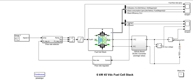
The input to the fuel rate selector block is the output of the signal builder block which is essentially drive cycle data and feedback from the fuel rate regulator.The signal builder signal is constructed using the time and current data associated with the UDDS drive cycle.A variable current_profile is created which has the time and current data. Each of the variables ie. the time and current is extracted. The variables are extracted using the following command
time=current_profile(:,1);
current=current_profile(:,2);
In the builder block in the signal option in new a custom signal can be created by the individual values.
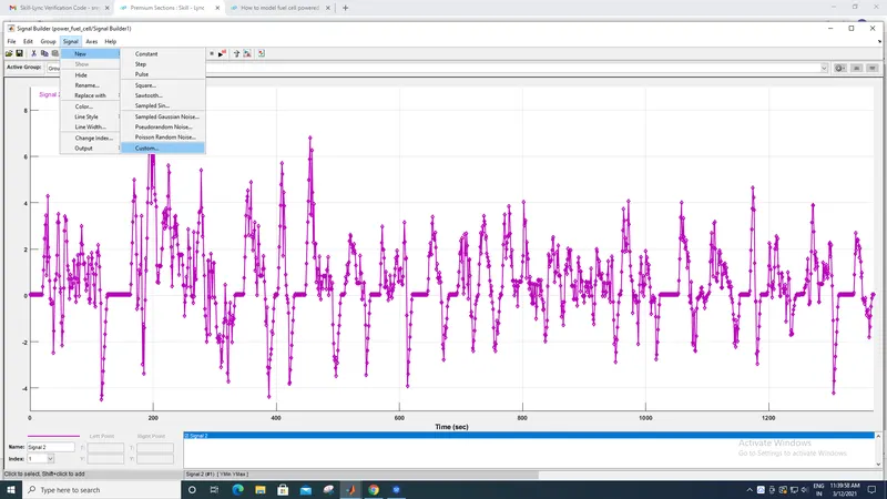
After the option is selected a box opens up asking to input the time and y axis variables.For the time option the variable time is entered and the y axis values the variable cuurent is entered.After the values are inputed the signal that is generated is the one above.
The drive cycle data along with the feedback from the fuel rate regulator is given as input to the fuel rate selector block.The fuel rate selector block subsystem is as follows
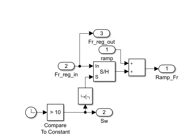
The clock output is continously checked with against a constant. This is also the sampling frequency. This is given as input to the edge detector block which is of rising edge type, this means the logic becomes 1 when there is a rising edge detected.The output of the edge detector block along with the fuel rate is given as input to the sample and hold block. The output of the sample and hold block is given to an adder whose other input is the drive cycle data.The outputs of the fuel rate selector block is given to a switch where the condition for passing the first signal is u2 should be greater than the threshold value.
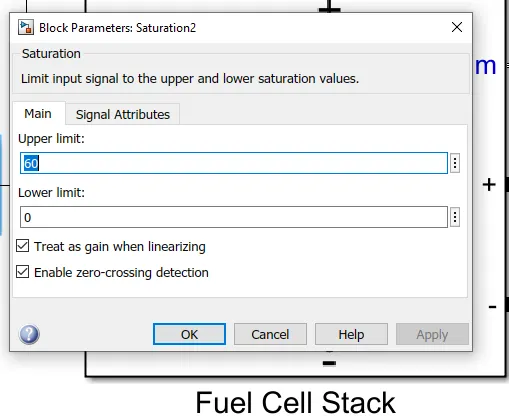
The upper limit for the flow has to be the maximum speed that is achieved in a drive cycle.The maximum speed in the UDDS drive cycle is 56.7.
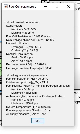
The fuel cell is the device that is responsible for producing power in a fuel cell car. The fuel that is hydrogen in this case has to be continously supplied to the cell and it can generate power. Compressed hydrogen along with oxygen has to be continously supplied to generate power. Unlike chemical cells the fuel cell cannot store energy.The fuel cell parameters are as follows
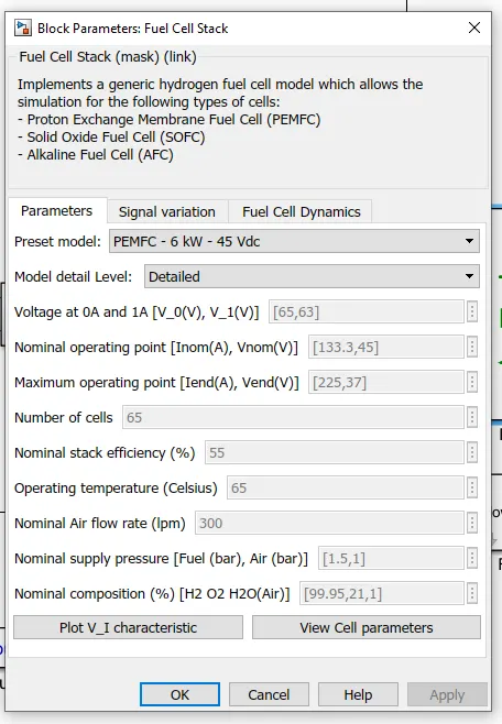
The fuel cell stack parameters are as follows
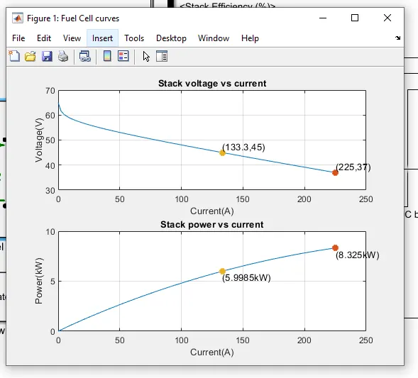
The VI characteristics of the fuel cell are as follows
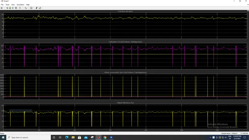
The fuel flow rate is 50 lpm for most of the drive cycle though it varies between 45 and 55 lpm. The oxygen utilisation is constant at 60% while that of hydrogen is as high as 100% to as low as 0% which means it load and power dependent.The fuel flow rate of hydrogen is not allowed to go more than 60 lpm and that of air is as high as 3750 lpm. The fuel cell stack is around 60% though at times it can become 0.
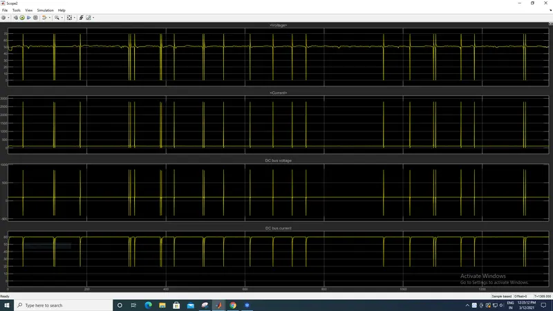
The voltage hovers at around 50V for most of the drive cycle but at times it does decrease to zero during the the same interval the current shoots up to 2750A otherwise it has average value of 118A. The DC bus voltage is at an average 100V but at times it can go as high 850V and 412V in the opposite direction.The DC bus current is at 60A for most of the drive cycle though it can drop to 20A at times. There tends to be a flactuation in the values when there is stress on the fuel to delivery high perfromance.
RESULT:
The fuel cell is modelled using MATLAB and its performance is commented upon.