Door Bell and Thermistor Controlled Fan using SImulink
AIM:
1.To create a simulation in such a manner that the switch is closed every two seconds
2.To create a simulation where the fan is turned on if and only if the temperature is more than 25C.
MODEL SETUP:
1.DOOR BELL:
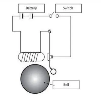
The circuit associated with the scenario is shown below
The block diagram with respect to the scenario is below
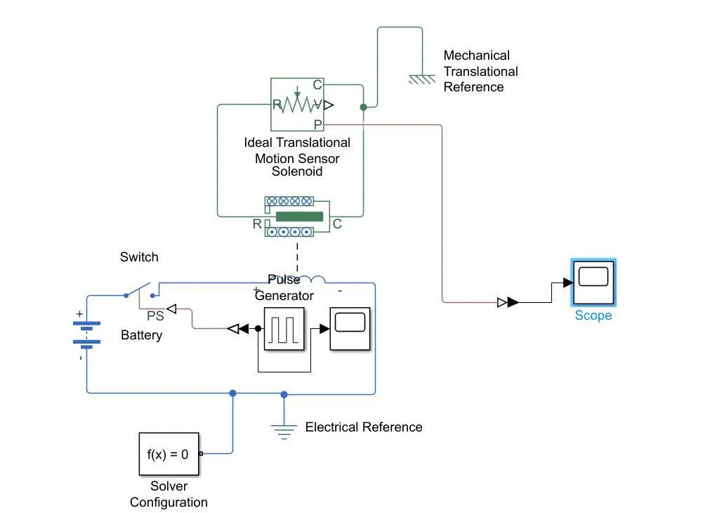
The PS switch is connected to a pulse generator through a Simulink PS covertor with appropriate parameters. The pulse generator is also connected to a scope. The PS switch is connected to a solenoid. The solenoid is connected to an ideal translational motion sensor. The position port of the ideal translational motion sensor is connected to a scope through a PS Simulink convertor. A battery is connected to complete the circuit. All the mechanical components are connected to a mechanical translational reference while the electrical components are connected to an electrical reference.
2.THERMISTOR CONTROLLED FAN:
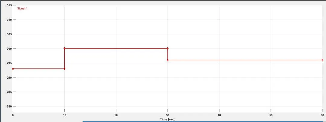
The temperature source is at 20C for the 10s then between 10s and 30s it is at 27C and then from 30s to 50 s it is at 23C. This kind of input is generated using a signal builder where the signal will look like the one below. The temperature which is to be plotted is to be in Kelvin only
The block diagram associated with the scenario is as follows
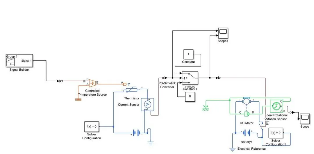
The required signal generated by the signal builder is given as input to the controlled temperature source through a Simulink PS convertor. The A terminal of the controlled temperature source is connected to a thermal reference. The controlled temperature source is connected to a thermistor which is then connected to an ammeter. A battery is also connected to the thermistor. The ammeter is connected to the middle port of the switch through a PS Simulink convertor. The other two ports are connected to constants. The input to the switch and its output are connected to a scope. The output of the switch is connected to a PS switch through a Simulink PS convertor. The PS switch is connected to DC motor and battery. The DC motor is connected to ideal rotational motion sensor which is connected to a scope through a PS Simulink convertor. All the electrical components are connected to an electrical reference while the mechanical components in this case are connected to a mechanical roational reference.
EXPLANATION:
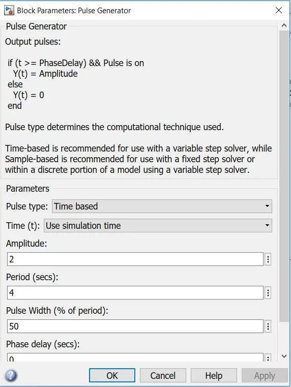
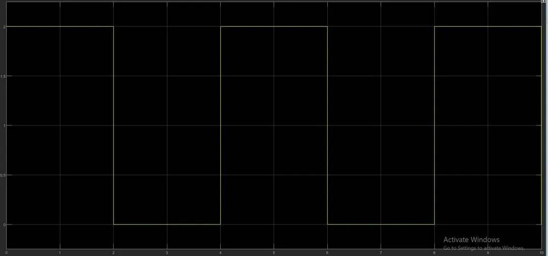
The pulse generator should caliberated in such a manner that the solenoid is energised every two seconds only. This can be acheived by the changing the parameters of the pulse generator. The amplitude is assigned the value 2 while the time period is 4 and the pulse width is 50% of the time period.
The signal generated will look like the one below
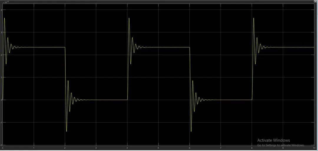
Unfortunately in Simulink there is no sound producing block and only the movement of the plunger can be observed through the plot which is as follows
2.THERMISTOR CONTROLLED FAN:
According to the condition in the scenario the fan is supposed to run only if the temperature is greater than 25C. For the above condition a constant is introduced into the simulation and run. The output of the ammeter is given as the threshold value to the switch.
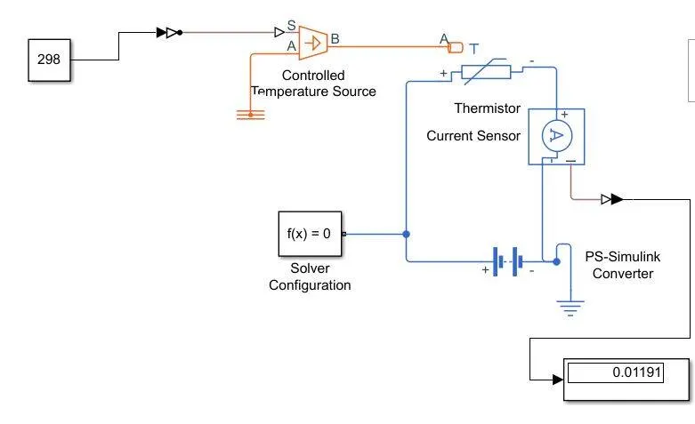
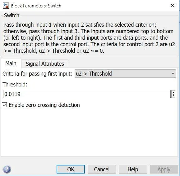
Then placing the signal builder back into the circuit the simulation is run again an the results are observed
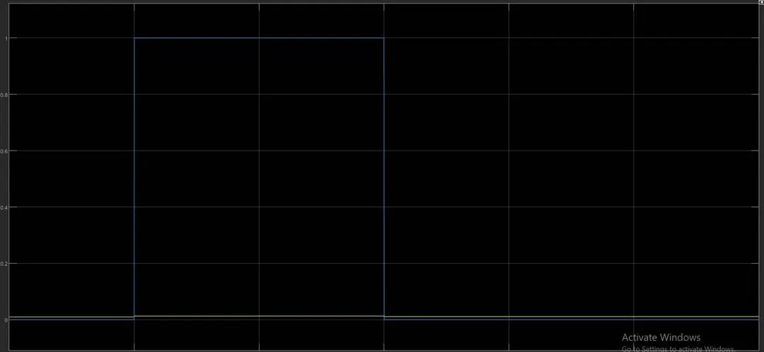
It can be observed that the switch toggles 0 to 1 for the time duration between 10s to 30s and while that happens the current can be observed to 0.01191 A, which means that the fan was on for only this duration and off during the others
RESULT:
1.The model is simulated where the switch is closed for 2s and then released and the movement of the plunger is observed.
2.The model is where the fan is turned on at temperature 25C or above using thermistor as the temperature sensor.