DC motor control using BJT H bridge and Modelling an EV using Four Quadrant Chopper DC drive
AIM:
1.To understand the speed control of DC motor using BJT H bridge
2.To understand the differences between the Four Quadrant Chopper DC drive model and H bridge model
3.To model an EV using the DC7 block
MODEL SETUP:
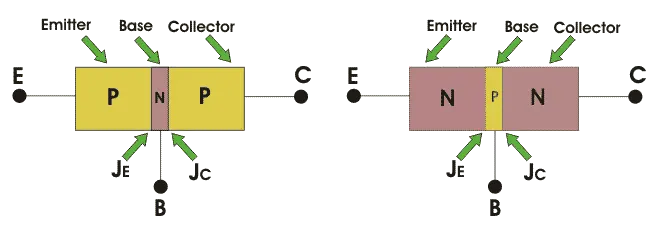
1.A BJT(Biploar Junction Transistor) is a three terminal semiconductor device.It is a current controlled device.The three terminals in the BJT are emitter, collector and base. In this type of device both electrons and holes are charge carriers. There are two types of BJT's NPN and PNP. In a NPN device a p type semiconductor is sandwhihced between two layers of n type semiconductor while in a PNP device a n type semiconductor is sandwhiched between two p type semiconductors.They look like as follows
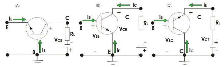
The device works in three different modes which are common base, common emitter and common collector configuration.In the common base mode the base is connected to ground while the other terminals either have inputs or outputs.In the common emitter mode the emitter is connected to ground while the other terminals either have inputs or outputs.In the common collector mode the collector is connected to ground while the other terminals either have inputs or outputs.The circuit for the same is as below
Under appropriate conditions the IGBT can be used in place of BJT's for simulation purposes
A MOSFET is a semiconductor device where the voltage determines the state of the device(Voltage controlled device).It is a three terminal device, the terminals are gate, source and drain.A MOSFET looks like the one below
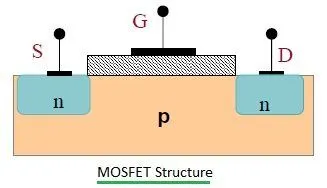
MOSFET's are primarily of two types enhancement type and depletion type MOSFET.A depletion type MOSFET requires the application of Gate Source Voltage in order to turn it off while the enhancement type MOSFET requires the application of Gate Source voltage in order to turn on the device
The IGBT(Insulated Gate Bipolar Transistor) is a combination of a BJT and MOSFET.It is three terminal semiconductor device which is voltage controlled.The three terminals are gate, collector and emiiter
The speed control of DC motor using BJT H bridge block is given below
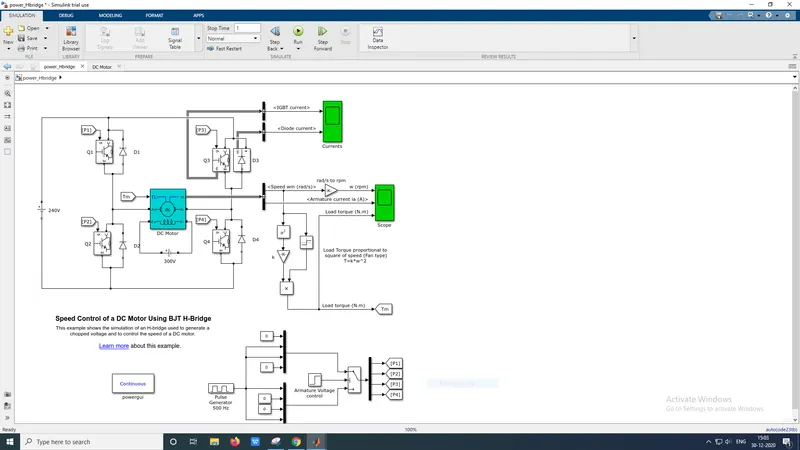
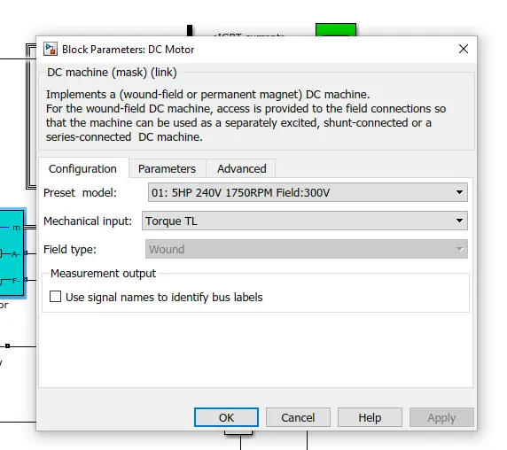
There is an external torque load on the motor.The DC motor takes a rated supply of 300V with 5HP and a maximum speed of 1750 RPM.
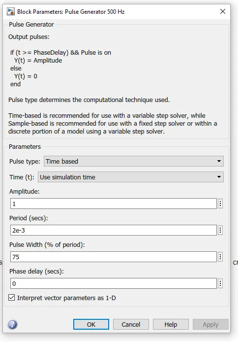
The H brigde consists of 4 IGBT's and diodes where a pair of them are connected in parallel. The IGBT switching sequence is responsible for the direction of rotation of motor.The pulse generator creates pulses which are given as input to the IGBTs. It has a duty cycle of 75% and a time period of 0.002s
When the model is simulated the following output is obtained in the scope
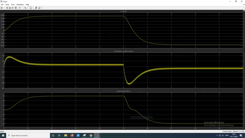
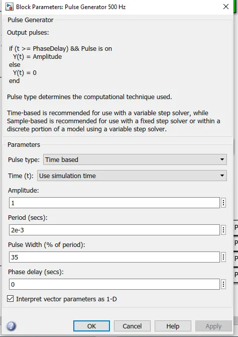
It is to be noted that at time t=0.5s the torque value starts to fall and gradually becomes zero, during this interval the armature current falls to a minimum value of -66A.Once the torque starts to become negative the value of current starts to shoot In order to avoid the sudden increase in the value of armature current the Pulse width of the pulse generator block can be changed.Initially the pulse width is set at 75% and then it is changed to 35%
After changing the value of the pulse width the model was again simulated and the output displayed on the scope is as follows
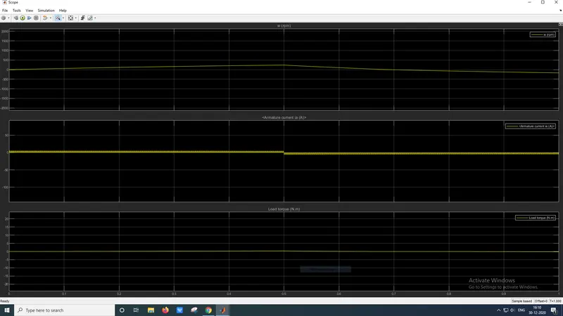
It is to be noted that the value of armature current is only slightly above zero and value doesnt shoot up when the direction of rotation of the motor is reversed.
2.The Four Quadrant Chopper DC drive has four different modes which are forward motoring, reverse motoring, forward braking and reversing braking while the BJT H bridge has only two modes of operation which are forward and reverse. It is the Four Quadrant Chopper DC drive is the component that is predominently used in electric vehicles
In BJT H bridge the polarity of the conducting devices decide the direction of the motor while in the Four Quadrant Chopper DC drive the gear in which the vehicle is in (forward or reverse) and the speed at which it is travelling decides the direction in which the motor rotates
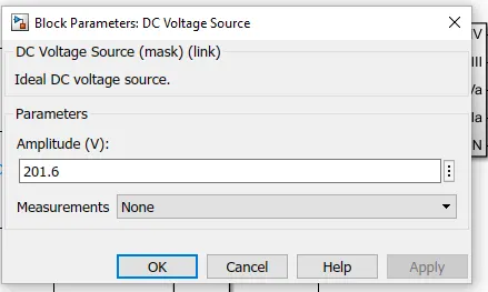
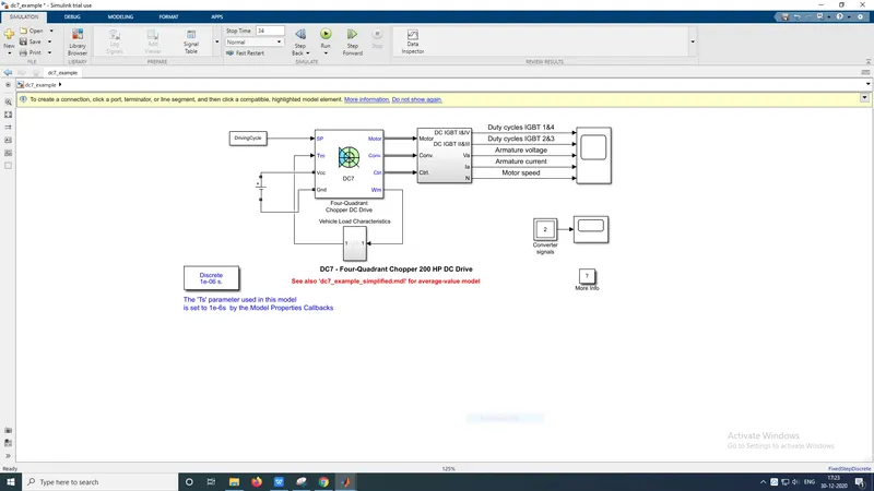
3.The energy source for the block is DC voltage source which has a capcity of 201.6V. The positive terminal of the DC voltage source is connected to the VCC input port of the Four Quadrant Chopper DC drive block while the negative terminal of the DC voltage source is connected to ground port of the Four Quadrant Chopper DC drive block. The parameters of the Dc voltage source block is below
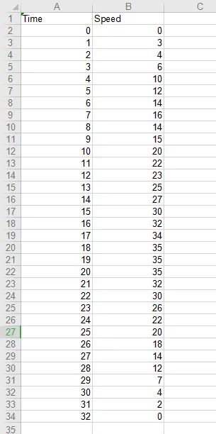
The driving cycle is imported from an exel file in the numerical matrix format which is then accessed using the from workspace block where the data parameter is given the value DrivingCycle
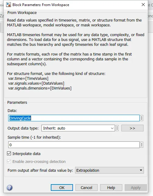
The from workspace block is then connected to the SP input port of the Four Quadrant Chopper DC drive block
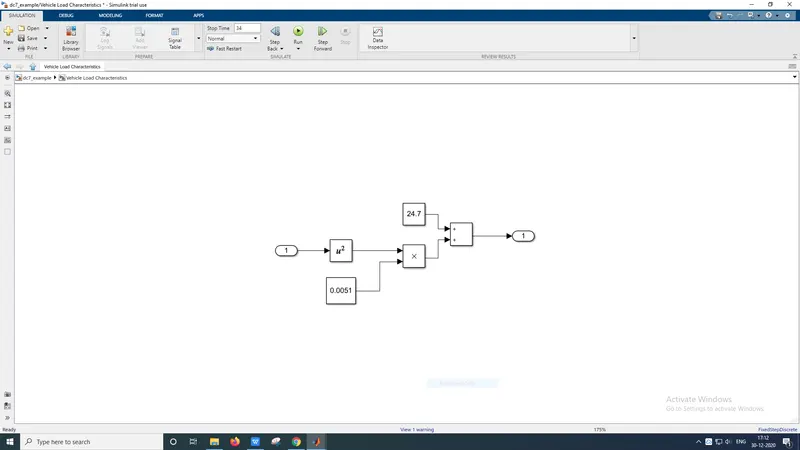
The vehicle load characteristics is modelled based on the equation 24.7+(0.0051)*w^2 which is created as a subsystem. The subsystem block is in the feedback loop.Since it is there in the feedback loop the input is obtained from the Wm output port of the Four Quadrant Chopper DC drive block. It is then squared and it is multiplied with the a constant value of 0.0051. The output of the product block is given as one of the inputs to add block along with a constant of 24.7. The output of the add block is given to the output port of the subsystem. The output port of the subsystem is connected to the Tm input port of the Four Quadrant Chopper DC drive block thus completing the feedback loop.
The entire EV block model will look as follows
The simulation time was changed to 34s in accordance to the driving cycle that has been provided.The model was simulated and the output on the scope is as follows
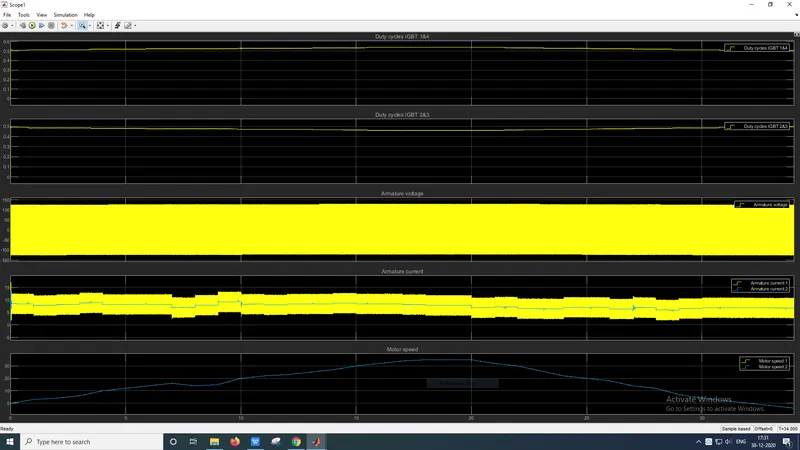
It is to be noted that the armature voltage osscilates between 120V and -120V. The armature current on the hand increases when the motor speed increases and decreases when the motor speed decreases.
RESULT:
1.The speed control of DC motor using BJT H bridge is modelled and understood
2..The differences between the Four Quadrant Chopper DC drive model and H bridge model are understood
3.An EV using the DC7 block is modelled