EV Drivetrain Analysis
AIM:
1.To explain about the various power converter converter circuits that are employed in an electric and hybrid electric vehicle
2. To find the steady state speed of the EV with the given parameters
3. To conclude whether the induction motor is better than the brushless motor or vice versa
MODEL SETUP:
1. Power converters can be classified into the following catagories:
AC to DC converter(rectifier):
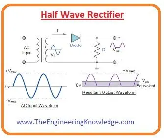
The AC currrent supply is continous in nature and has a frequency of 50Hz in India which means for every 0.01 second the supply switches polarity from positive to negative or vice versa. Rectifiers can be either full wave rectifiers or half wave rectifiers. In a half rectifer either only the positive half cycle or negative half cycle is converted into DC which is unidirectional in nature while the other half cycle is ignored. There is no output produced for this half cycle. The circuit of a half wave rectifier along with its input and output waveform is as follows:
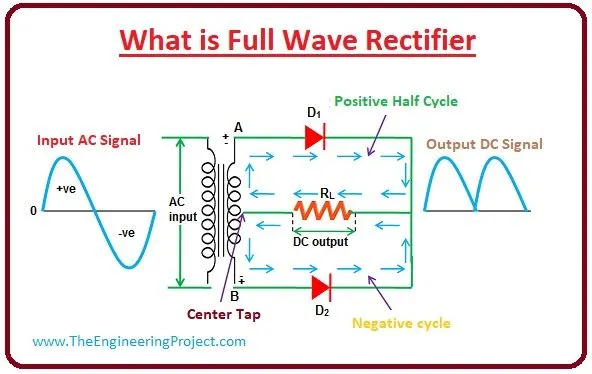
In a full wave rectifier the current passes through the diode D1 in the positive half cycle and unlike in the half wave rectifer there is a second diode D2 through which the current passes in the negative half cycle.The circuit of the full wave rectifier along with the input and waveform is given below
The drawbacks present in the full wave rectifer are as follows:
i.The cost of the center tap transformer is high
ii.The DC output voltage is small since each of the diodes use only half the secondary voltage of the transformer.
iii.When a small voltage has to be rectified the full wave rectifier is not suitable
All the above said disadvantages are overcome in a bridge rectifier.
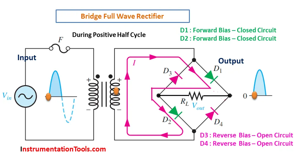
In a full wave bridge rectifier during the positive half cycle the diodes D1 and D2 are forward biased and D3 and D4 are reverse biased as a result of which D1 and D2 conduct while D3 and D4 dont.During the negative half cycle the diodes D1 and D2 are reverse biased and D3 and D4 are forward biased as a result of which D3 and D4 conduct while D1 and D2 dont.The input and output waveform along with circuit diagram of the full wave bridge rectifer is given below
During the process of regenerative braking the current produced is alternative in nature which cannot be used by the battery directly. This is given as input to the AC-->DC converter. The output of the converter can be used to charge the battery
DC to AC converter(inverter):
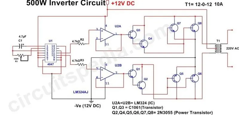
The inverter circuit basically converts Dc to AC.The output voltage, frequency and power all depend on various components used and its applications.The 3 major types of inverters include sine wave inverter,modified sine wave inverter and square wave inverter.The inverter circuit where the input voltage is 12 V DC and the output is 220V AC as in a typical inverter circuit used at home is given below
The applications of inverter include:
i.In solar energy power systems
ii. As standalone inverters
iii.Can be UPS systems
In an electric or hybrid electric vehicle the output of the battery is DC in nature while the required input to the motor is AC.The battery output is given to an inverter circuit and the output is given to the AC motor.
DC to DC converter(chopper):
A chppoer circuit basically converts a fixed DC voltage/power into variable DC voltage/power.The chopper can be classifed into the following:
i.Type A
ii.Type B
iii.Type C
iv.Type D
v.Type E
The type A and type B choppers are single quadrant choppers(A is first quadrant while B is second quadrant), the Type C and D are two quadrant choppers(C is first and second quadrant while D is first and fourth) , Type E is a four quadrant chopper.
The chopper circuit along with the input and output waveforms is given below
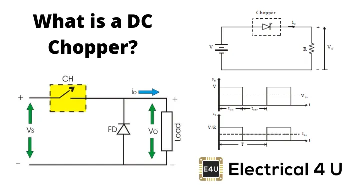
In an electric or hybrid electric vehicle the battery capacity is say 100V, all the auxillary components work at much lower voltages and such a high voltage is not required. The output from the battery is given as input to the chopper circuit which reduces the DC voltage to the required value which is then given as input to the auxillary devices.
AC to AC converter:
The AC to AC converter is a circuit which converts input which is AC with one frequency and power to AC with another frequency and power. The AC to AC converter is used in Variable frequency drive is given as input to the induction motor.The single phase to single phase cycloconveter circuit is as follows:
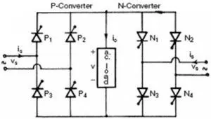
This kind of converter does really find an application in an electric or hybrid electric vehicle. The best application for such a converter is a fan regulator where the input voltage to the motor of the fan can be varied in order to be able to control the speed of the fan.
2.
The electric vehicle power train has a battery pack of 72V, with rated armature voltage Va of 72V and rated armature current Ia of. The armature resistance value Ra is 0.5Ω. The motor constant kΦ is 0.7 Vs.The chopper switching frequency is 400 Hz. The vehicle speed torque characteristics is define by the following equation
Tv=24.7+(0.0051)ω2
The speed torque characteristics of DC machine relates torque and speed as follows
ω=((V/kΦ)-(Ra/(kΦ)2))*T
The duty cycle is 70% and hence the voltage changes from 72V to 50.4V
ω=(50.4/0.7)-(0.5/0.49)*T
=72-1.02T
T=(72-ω)/1.02
=70.58-0.98ω
For steady state condition Tv and T must be equal
24.7+(0.0051)ω2=70.58-0.98ω
(0.0051)ω2+0.98ω-45.88=0
ω=38.921 or -231.078
Since the vehicle cannot move with negative speed ω=38.921 rad/s
3.The author feels that the industry of electric vehicles is constantly evovling and that the DC brushless motor and induction motor are equally good to propel vehicles. In the start there were DC brush motors and lead acid batteries which were replaced by DC brushless motor or induction and lithium ion batteries eventually. The replacement proved to be more effcient.
In a DC brushless motor the heating of the rotor is lesser when compared to that of an induction motor.The motor can operate at unity power factor which means at peak point performance the efficiency of the DC brushless motor will be higher than that of the induction motor.In an ideal motor the magnetic field is produced by permamnent magnets.When there is maximum torque requirement the magnetic field has to be maximum in order to reduce the motor and inverter currents.This ensure efficiency. Likewise when there is low torque demand the magnetic field strength should be dcreased so as to decrease the eddy current losses and hysteresis losses.With a permanent magnet in place the mechanism to change the magnetic field strength is compicated. The cost of the the permamanent magnet is also higher. As the size of the machine increases the magnetic losses associated with it also increases.
In an induction motor the magnetic field strength is adjustable since the voltage is proportional to the frequency.At lower loads the inverter can reduce the voltage therby reducing the magnetic losses and increasing efficiency. When the size of the achine is increased it doesnt necessarily result in reduced efficiency in case of an induction motor. This being the case it is preffered when peak performance is needed.
Overall the DC brushless motor and induction motor are equally competent each with its pros and cons according to the author