Week 6 Fuel cell powered vehicle model
The objective is to model a fuel cell powered electric vehicle using simulink.
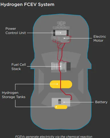
A fuel cell powered electric vehicle derives its power by converting energy stored in an electrochemical reaction into electrical energy. The fuel typically hydrogen is used to make a reaction with oxygen which yields water, electricity and heat as products. The reaction is clean, effcient and quiet.
PEM( proton exchange membrane) type fuel cell is the widely used type of hydrogen fuel cell in the industry.
--MODEL--
A fuel cell model is already present in the matlab. It can be accessed by typing "power_fuel_cell" in the command window of matlab.
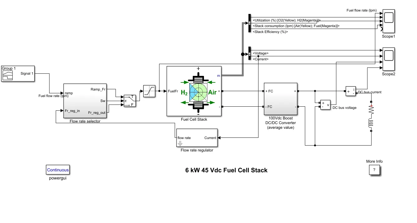
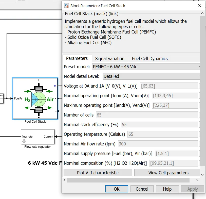
The model consists of a fuel cell stack PEMFC with a power rating of 6 kW and the nominal voltage of 45 VDC. The fuel flowing into the cell is controlled by the flow rate selector. In the default model, the initial ramp block is used to define the flow rate and the time of flow.Usually, for the sake of modeeling , drive cycle data is used instead of ramp.
We use a user defined signal builder to analyse the behavior of the fuel sell stack. The signal builder has the following data:
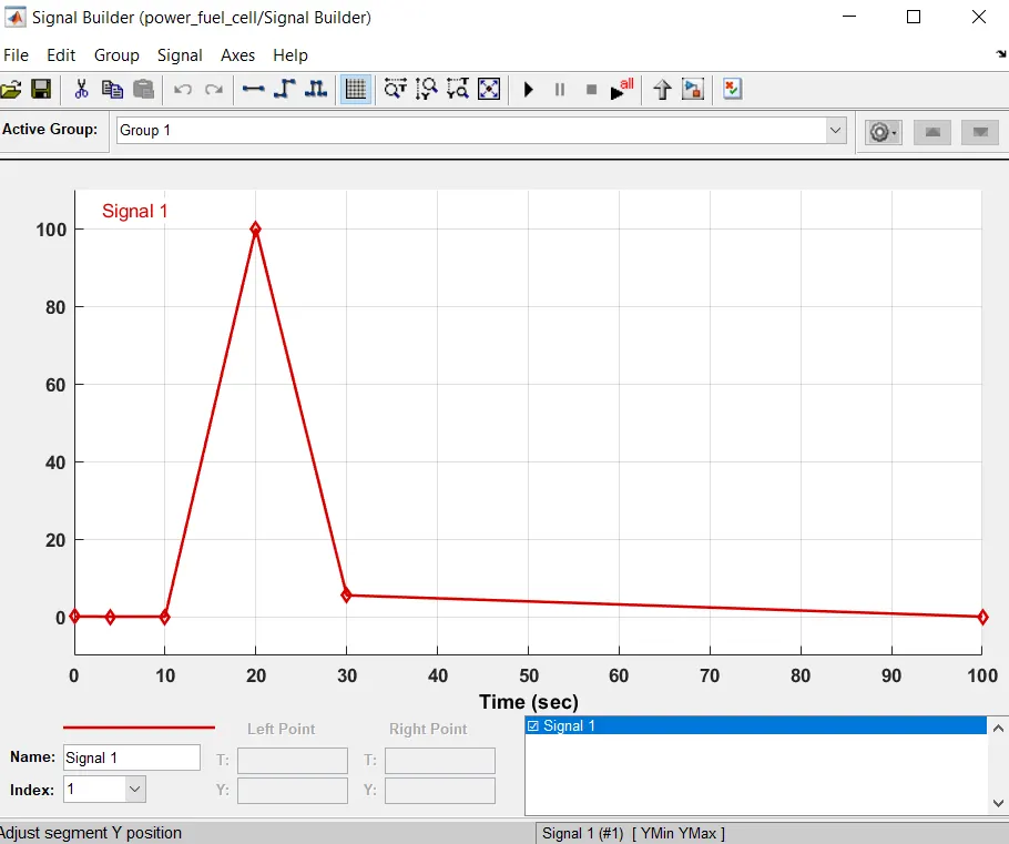
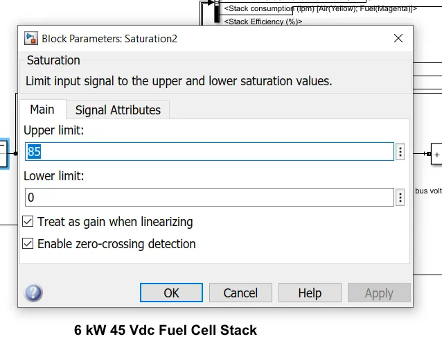
The block then sends the signal to the fuel cell. The signal is constricted to value of 85 using saturation block.
During the first 10 seconds, the signal builder block sends a value of 0. The signal received by the current output is converted into equivalent fuel requirement by the fuel regulator block and this value is fed into the fuel cell. After 10 seconds, the value of the flow rate is dictated by both the signal builder and fuel regulator output, by switching the ports in flow rate selector. The saturation block then constraints the value between 0 and 85 lpm.
The Voltage and the curent produced by the Fuel cell stack is obtained by connecting the ports to the scope
A DC/DC boost convertor is used to increase the voltage porduced by the fuel cell and supply it to the vehicle represented by the series RLC branch to the right. The voltage and current are measured using DC voltage and current measurement blocks. These are also fed into thescope.
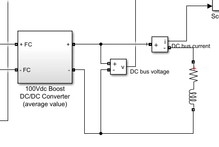
The fuel cell stack parameters related to fuel consumption, flow rate, Hydrogen and Oxygen utilization, air consumption and efficiency are then studied by feeding their output ports to a different scope. The bus selector blocks are used to isolate the required outputs and study them individually.
The values taken in the simulation are default. We can change the values are required by pening respective blocks. For the fuel cell stackblock, the model used can be changed using the drop down menu.
--Result--
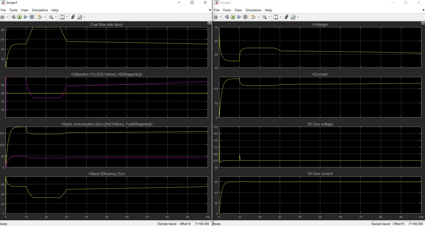
From the plots, we can observe :
- The oxygen consumption remains constant through out.
- even though the fuel flow rate increase at t=10 secs, the utilization of H2 decreases.
- The voltage at the beginning , of the cell stack is around 70 and the converter applies the voltage at 100 volts. The convertor tries to keep the voltage at 100 v and ripples are observed when there is momentary changes in the cell voltage.
- at t=10 secs, the flow rate increases, the voltage increases. This results in reduction in current value. This results in decrease in stack consumption. When there is a reduction in stack consumption, the stack efficiency also reduces.