Creating connection for Rear door Using ANSA
Aim:
The aim of the challenge is to deploy connections to the given Rear Door FEA model.
Objective:
- Analyze the FEA model and apply Property ID to each individual component.
- Add appropriate connections were needed in the FEA model.
Types of connections.
The different types of connections we will be using in the challenge are mentioned below.
- Cluster RBE2
- Two Node RBE2 elements to represent the bolt with the body.
- RBE2 Element with Mass representing components attached to the door frame.
- RBE3-HEXA-RBE3 type joint representing Spot welds.
- Overlap-SHELL type joint representing Overlap Seam Welds.
- RBE3-CBUSH-RBE3 type joint representing damping Areas. (Rubber window line)
Procedure.
First and foremost we will analyze the FEA geometry provided. (Rear Door model)
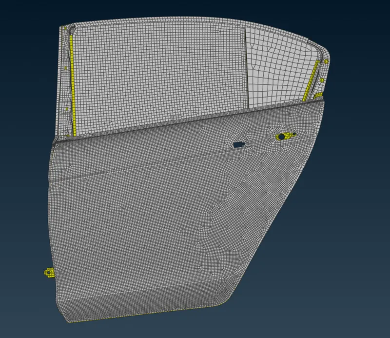
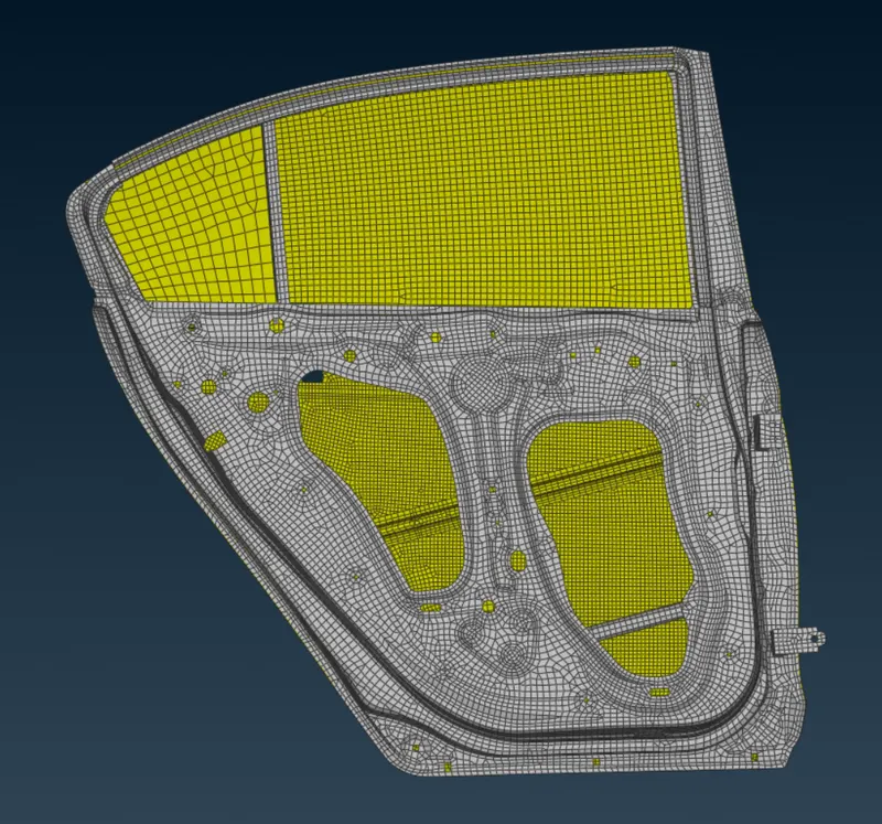
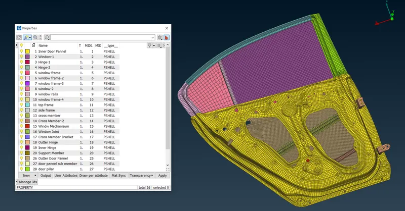
All the components have one property ID.
We assign different property IDs to each component.
Cluster RBE2
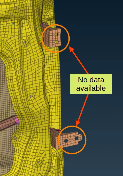
In some of the locations where we don’t have bolt or weld data, we use Cluster RBE2 to represent a connection.
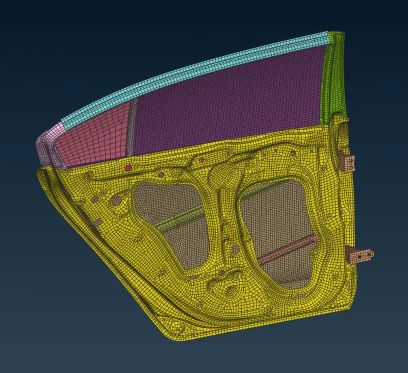
To apply an RBE2 element we must go to the DECK menu in ANSA. In the DECK menu, there is a command name RBE2.
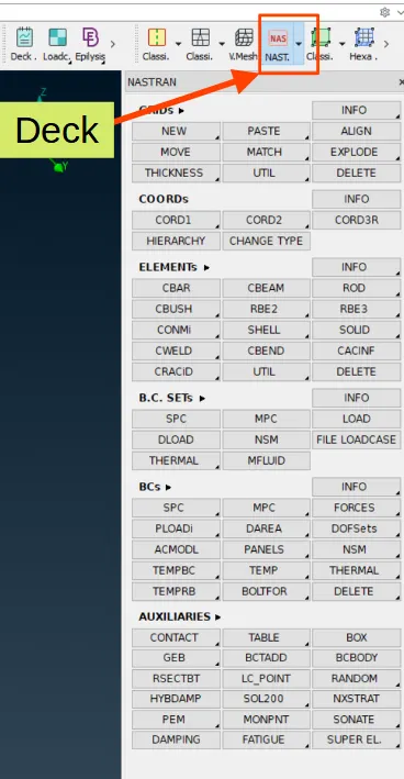
The RBE2 command has 2 options
- Many nodes RBE2.
- Two node RBE2.
For the cluster RBE2 element we will select the first option.
Now we must select the hole perimeter to deploy the RBE2 element.
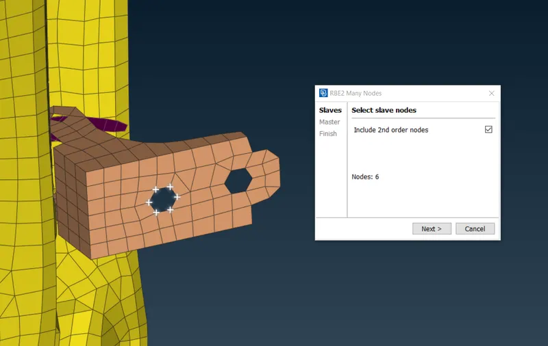
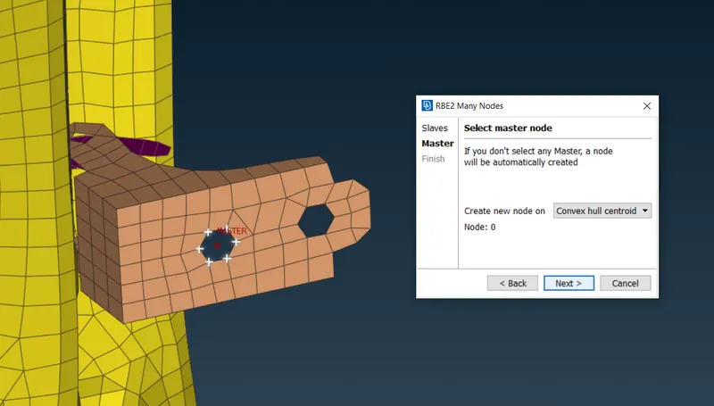
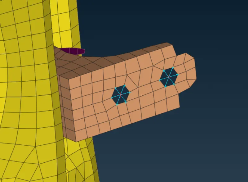
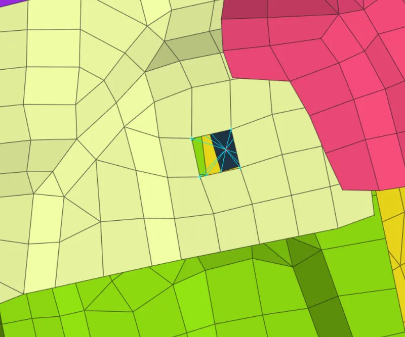
we can also connect multiple components with one RBE2 Element.
Two Node RBE2 elements to represent Bolt with Body of a Hinge.
When we have two components with match holes, and we know for sure there will a bolt to connect these two features or hinge, this method can be used.
First, we define the COG point for the holes.
Now we convert this point into a feature that will represent a connection,
As we know this is going to be a bolt, we will select BOLT as an option.
Now we can deploy the RBE2 element using Connections Manager.
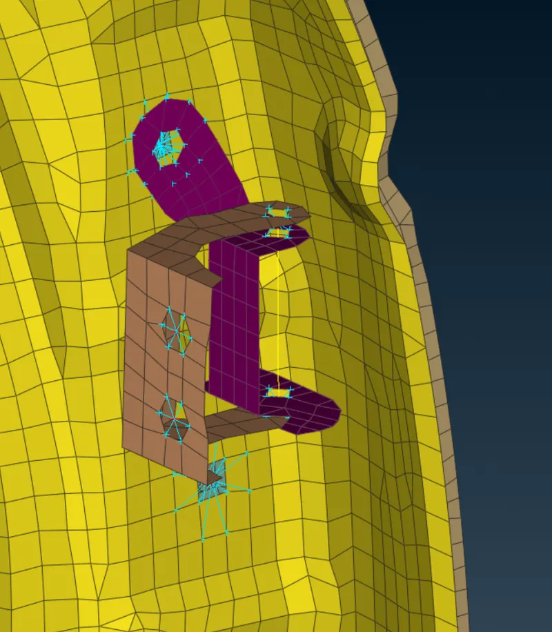
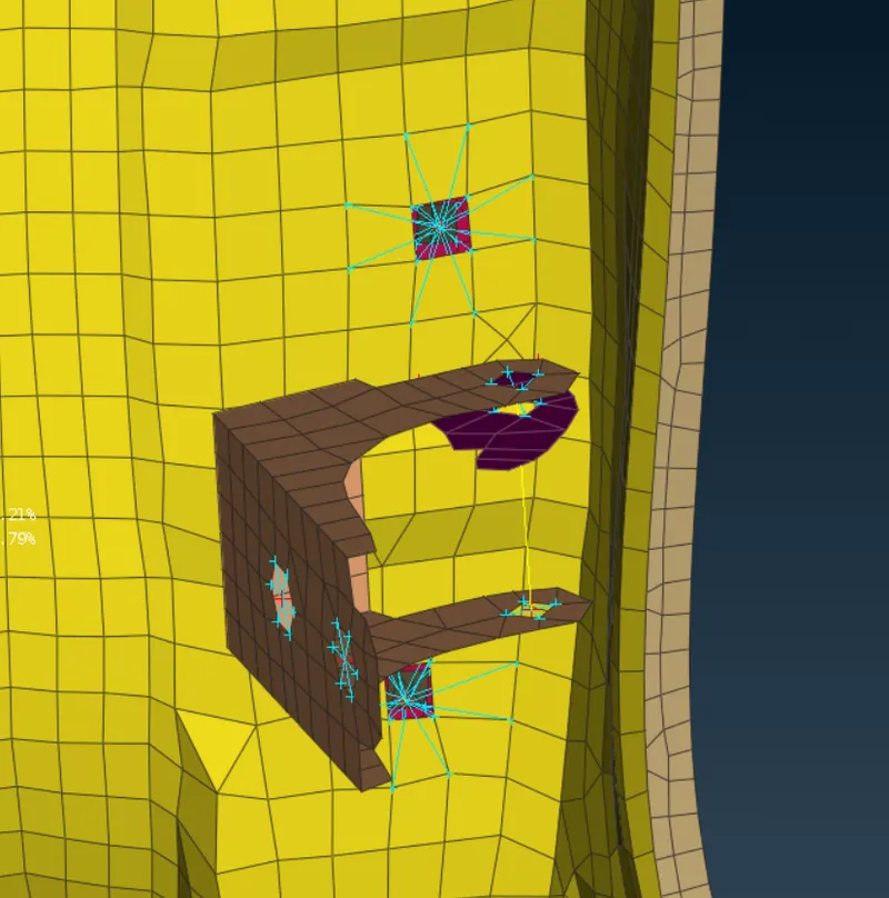
RBE2 Element with Mass representing components attached to the door frame.
Some components or mechanisms will be attached to the door with definite mass. We can define those components in ANSA.
For this situation, we take the example of the door handle.
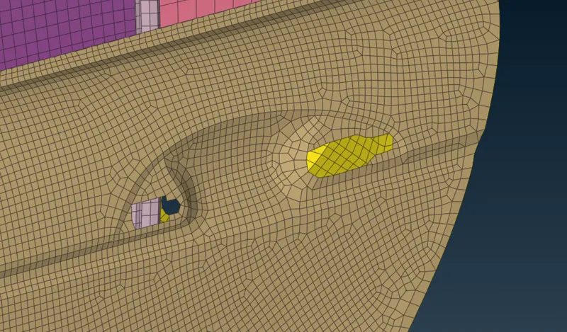
First, we deploy cluster RBE2 on the 2 slots where we attach the door handle.
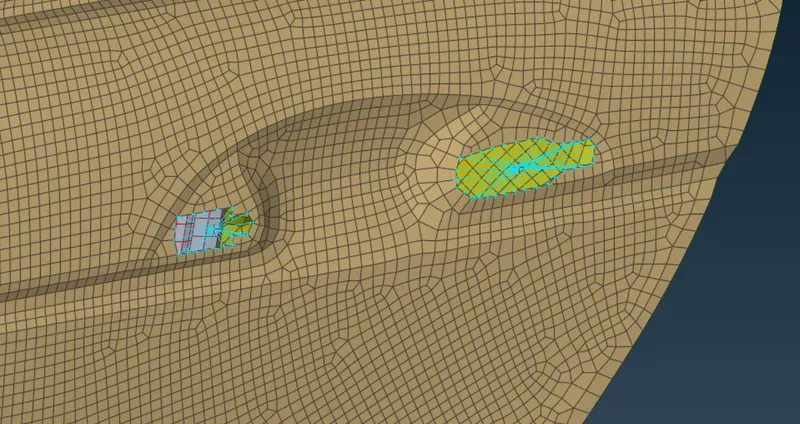
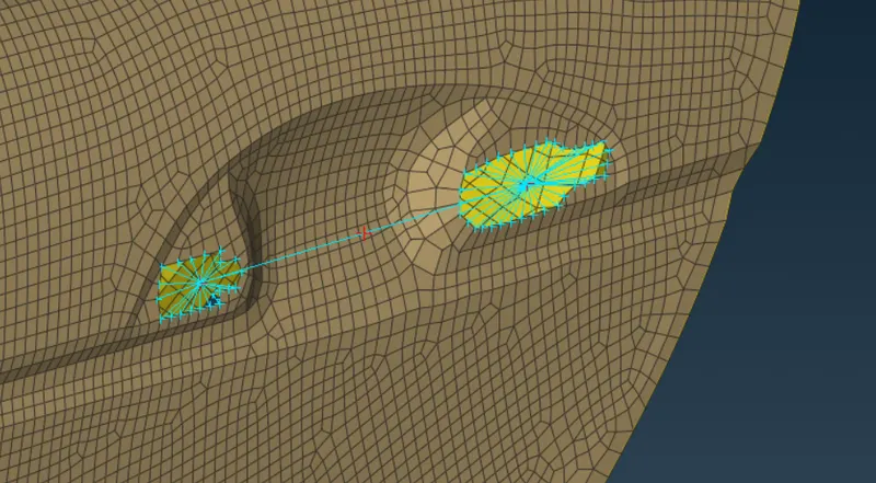
Now we deploy another RBE2 element which will connect the 2-door handle RBE2 element.
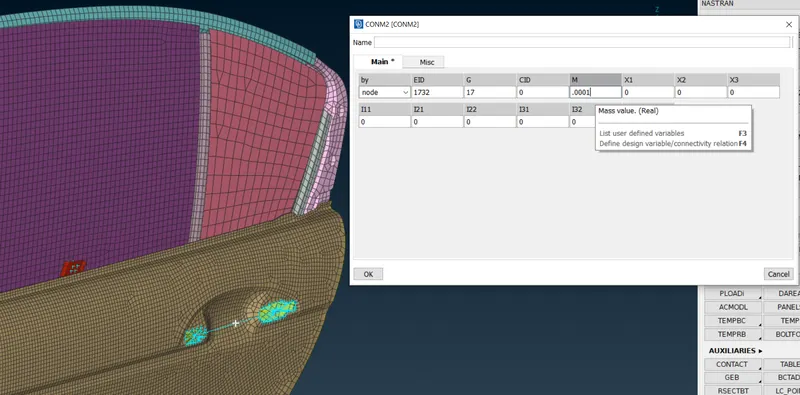
Now we use the CONMi command present in the DECK menu. This command is used to assign mass to the RBE2 elements.
RBE3-HEXA-RBE3 type joint representing Spot welds.
Some components will be joined together with the weld. Generally in automotive 2 types are widely used.
- Seam welds
- Spot welds.
In ANSA Spot welds can be represented using REB3-HEXA-RBE3 type joint.
We have two components in our challenge that are connected to each other using spot weld, to deploy the REB3-HEXA-RBE3 joint first we define the area we want spot weld.
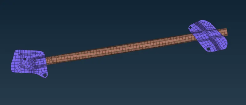
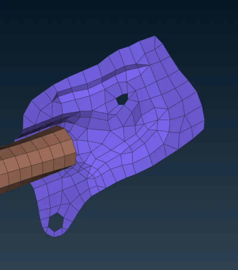
We will create a COG point on the feature where we want spot weld
The COG point can be converted into a spot weld point using the CONVERT command in ANSA.
Now we use this point to deploy connections using the CONNECTION MANAGER command in ANSA.
We must input the 2 PIDs of the components we want to join, select the connection type to be REB3-HEXA-RBE3, and create a new PID for the Spot Weld.
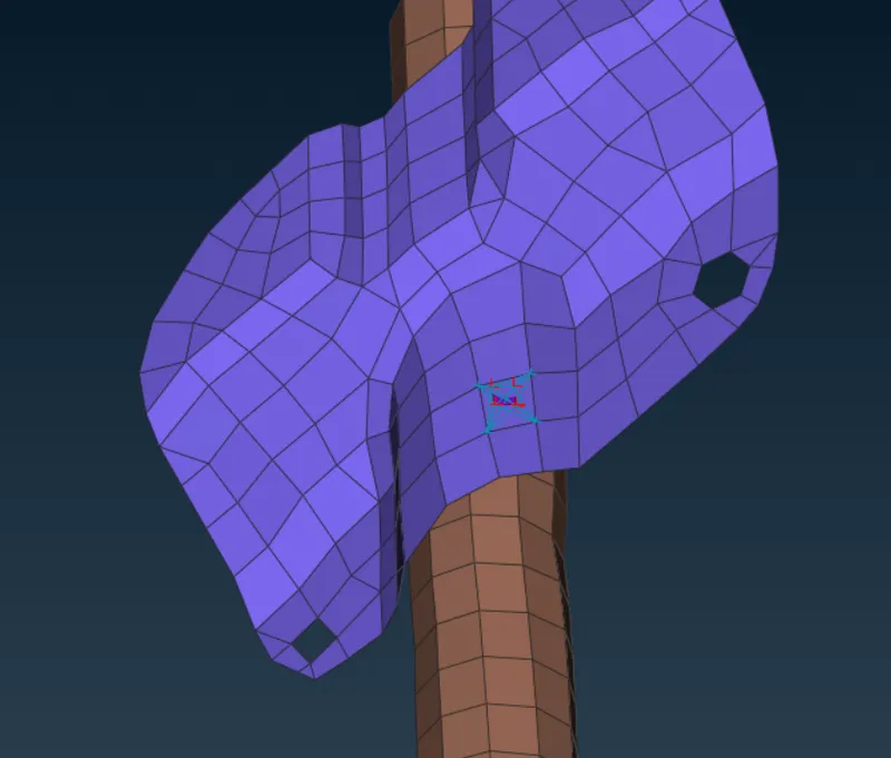
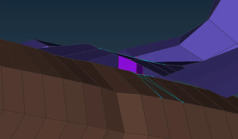
This is how a spot weld is represented in ANSA.
RBE3-CBUSH-RBE3 type joint representing damping Areas. (Rubber window line)
In the real world, almost every automotive window will have a Rubber window line attached to the door frame.
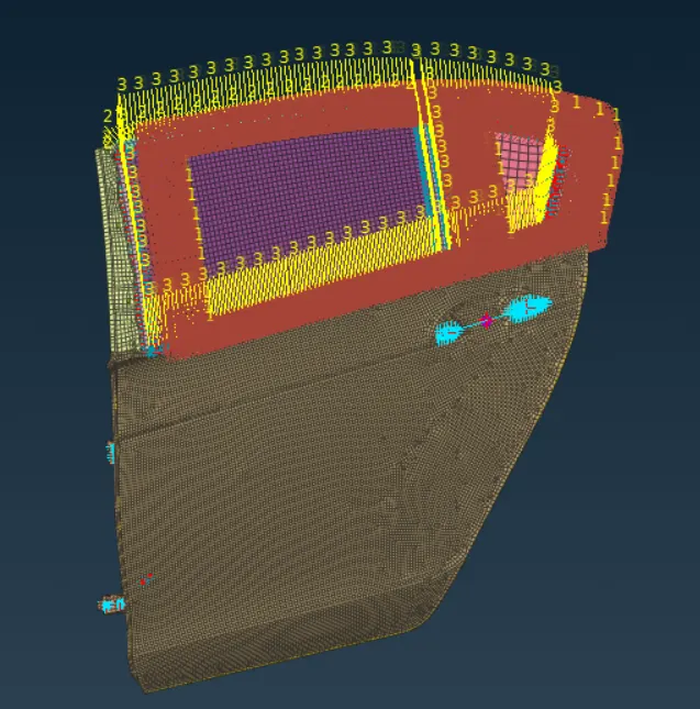
This rubber line will have some damping properties, we can represent the rubber line using the RBE3-CBUSH-RBE3 joint in ANSA.
To deploy this joint we must first define the periphery of the rubber line. This can be done using 3D curves.
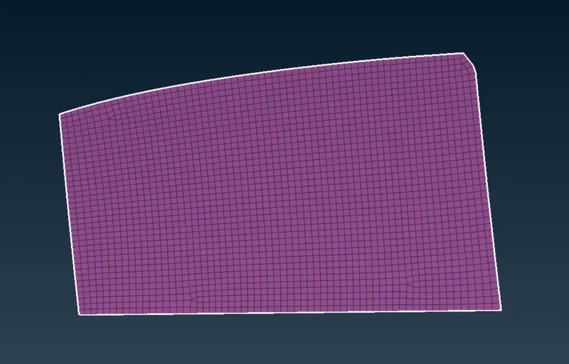
These 3D curves will be then converted into SPOT LINE.
Now we can deploy the RBE3-CBUSH-RBE3 joint in CONNECTIONS MANAGER using the SPOT LINE we created.
The following are the inputs we must provide,
- PID of Window and Door Frame.
- Connection type (to be RBE3-CBUSH-RBE3).
- Separate PID for CBUSH element.
- Key in the stiffness value of the CBUSH element in all 6 directions.
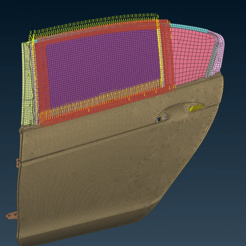
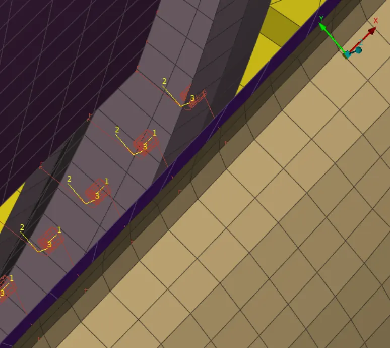
Now all these RBE3-CBUSH-RBE3 joint is using a local coordinate system, we must align all the CBUSH element as per our main coordinate system.
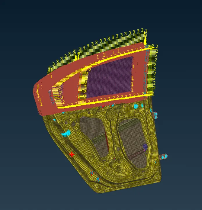
After connecting all the components using the above methods over Connections challenge is complete.
LEARNING OUTCOME:
By doing this challenge I learned,
- How to connect 2 components in ANSA using RBE2
- How to represent bolts in ANSA.
- How to represent Spot welds in ANSA.
- How to use CBUSH element for parts with damping property.
CONCLUSION:
This concludes the connection challenge