Meshing of the Suspension Assembly Using ANSA
Aim:
The aim of this project is to generate an FEA model of a given suspension Assembly.
Objective:
- Analyze the CAD model for any geometry errors. If present, then correct it. And assign separate properties to each component.
- Extract mid-surface and deploy 2D mesh on components with a thickness less than or equal to 5 mm.
- Deploy surface mesh (2D) and generate unstructured 3D mesh on remaining components.
- Deploy bolt and weld connections.
Element Quality Criteria for this challenge.
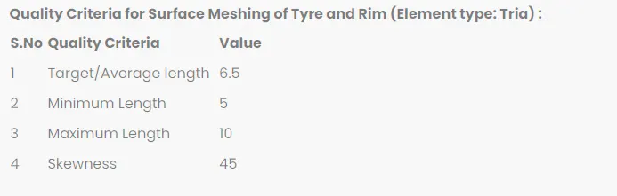
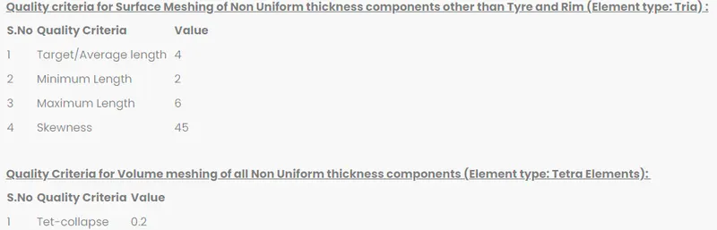
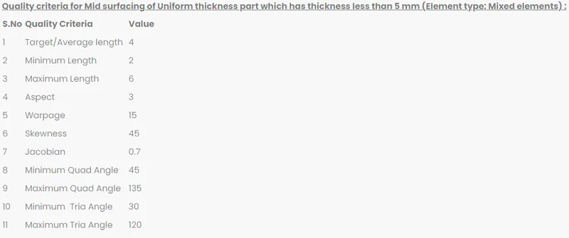
Procedure.
- Analyze the CAD model for any geometry errors. If present, then correct it. And assign separate properties to each component.
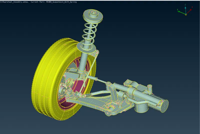
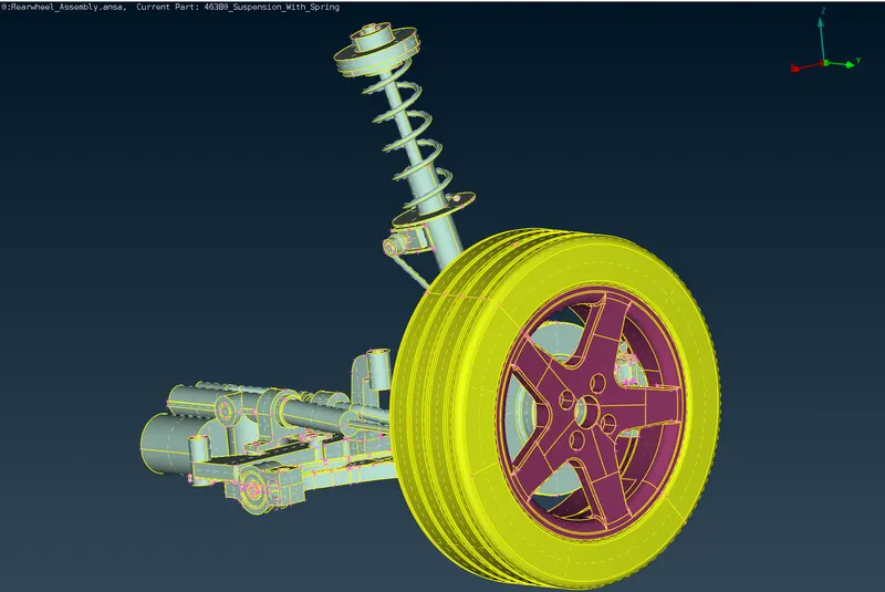
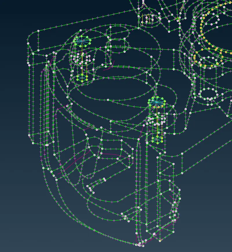
After importing the CAD geometry to ANSA we checked for any geometry error that came with the model. To do so we go to the Check-Geometry option in ANSA.
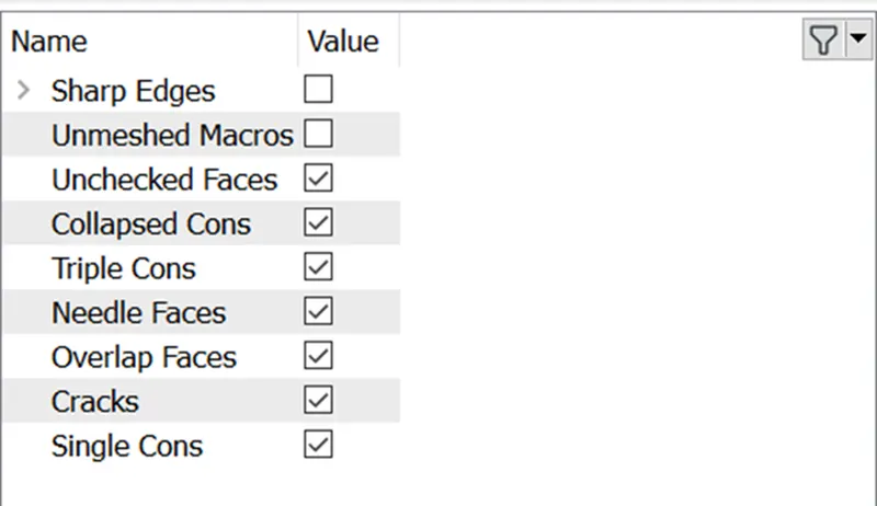
ANSA will check the CAD model over the criteria mentioned above, and if the model fails, ANSA will prompt any error describing the reason for the error.
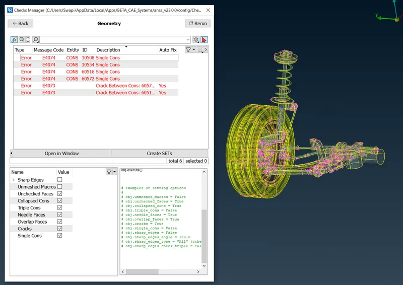
As we executed the geometry check function, we found some errors. Now there are 2 ways to solve these errors:
- Auto fix option that ANSA provides. (ANSA will fix the failing features.)
- Manual fix-User will manually fix the failing faces or Cons.
In our challenge, ANSA was able to auto-fix all the errors.
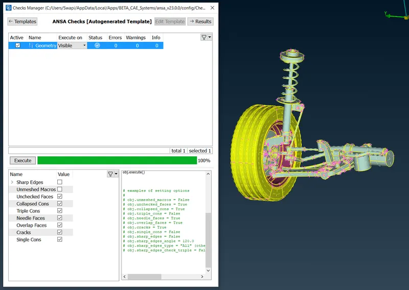
Below is the list of the components.
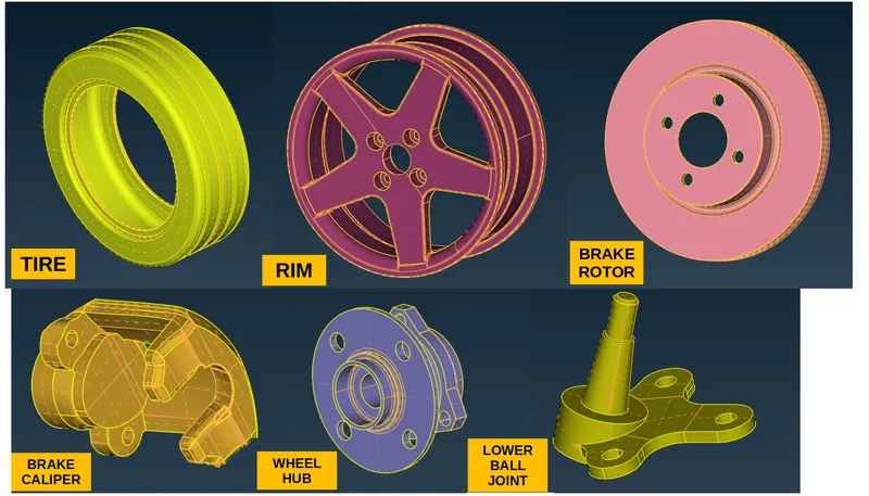
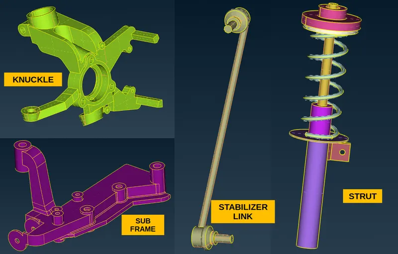
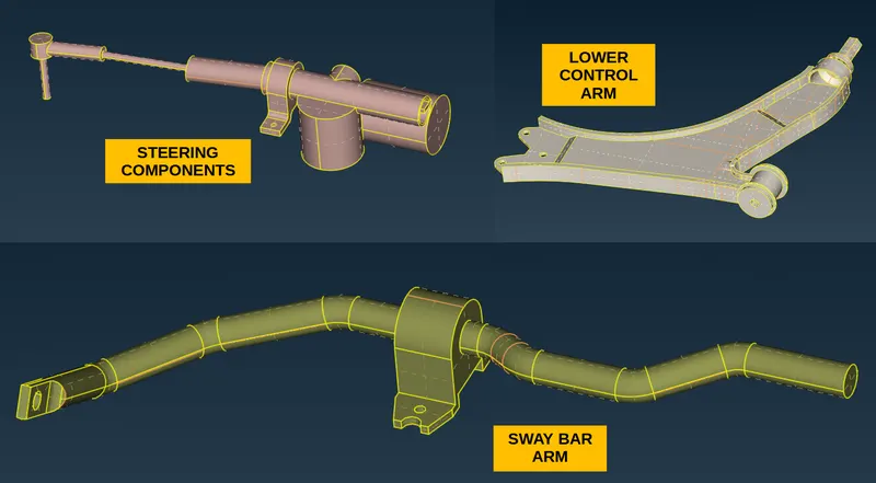
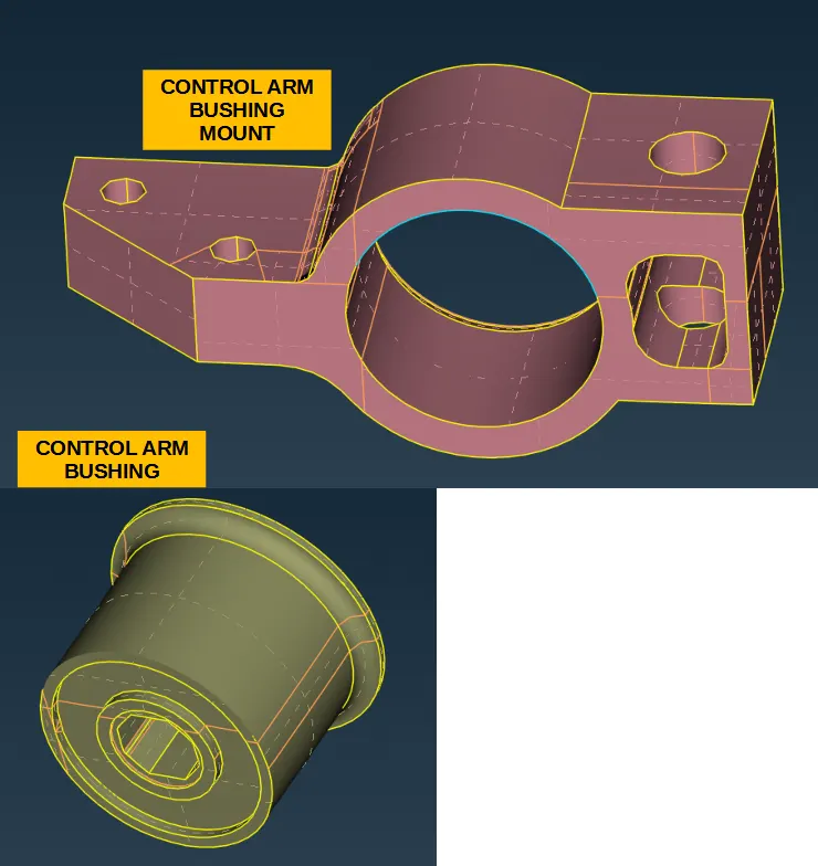
A separate property card is generated for each component.
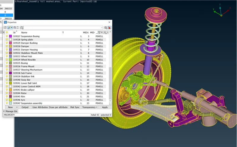
- Extract mid-surface and deploy 2D mesh on components with a thickness less than or equal to 5 mm.
After a quick thickness check, 2 components have thicknesses of less than 5mm.
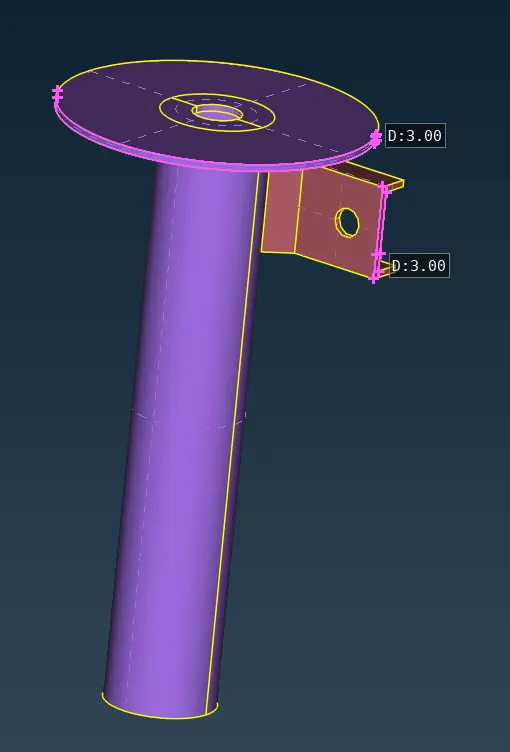
We can extract mid-surface from these components and generate 2d mesh.
To extract mid-surface we can use OFFSET or MIDSURFACE Command.
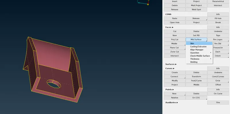
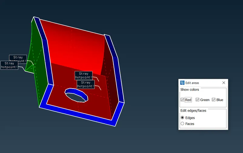
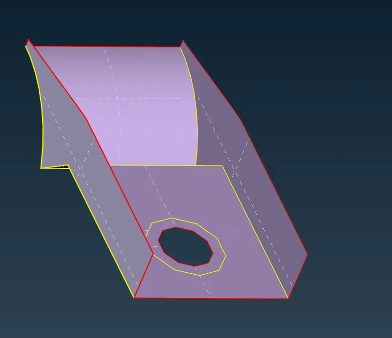
By using the same method we can extract mid-surface and the deploy 2D mesh.
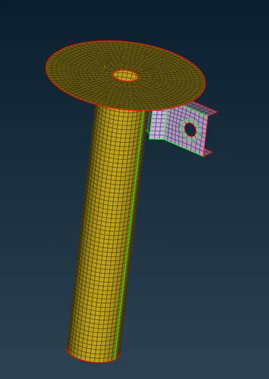
- Deploy surface mesh (2D) and generate unstructured 3D mesh on remaining components.
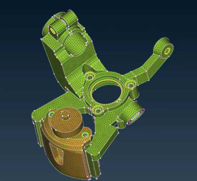
For the rest of the components, we will generate a surface mesh and then deploy an unstructured 3D mesh.
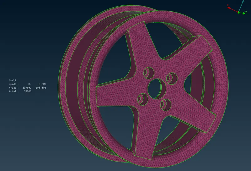
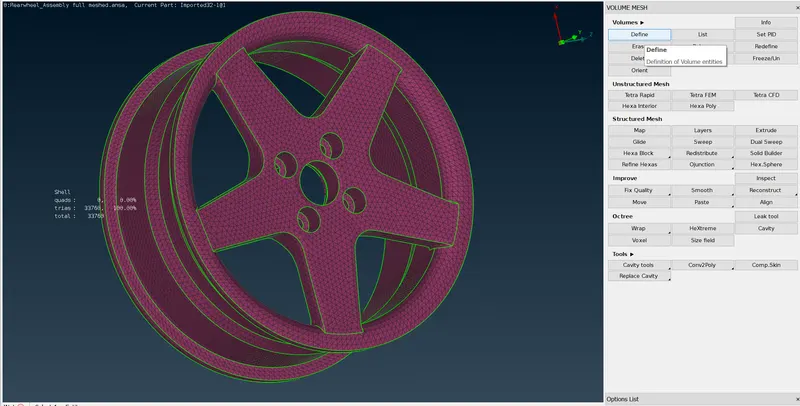
First, we define the volume for our component and deploy unstructured 3D mesh.
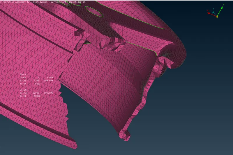
By following the same procedure we can deploy 3D mesh on all the remaining components.
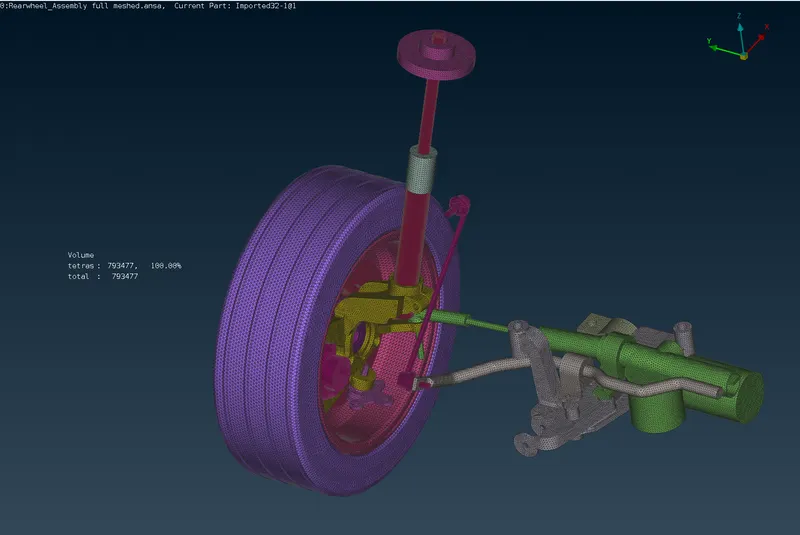
The spring in the strut assembly has to be represented as a CBAR element.
To capture the spring FEA first create a middle construction curve from the spring using the MIDDLE command in curves.
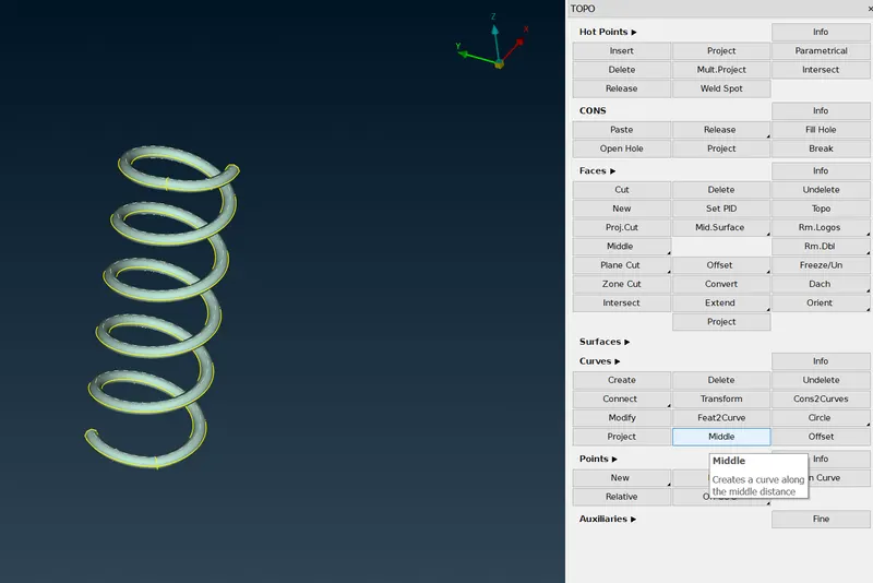
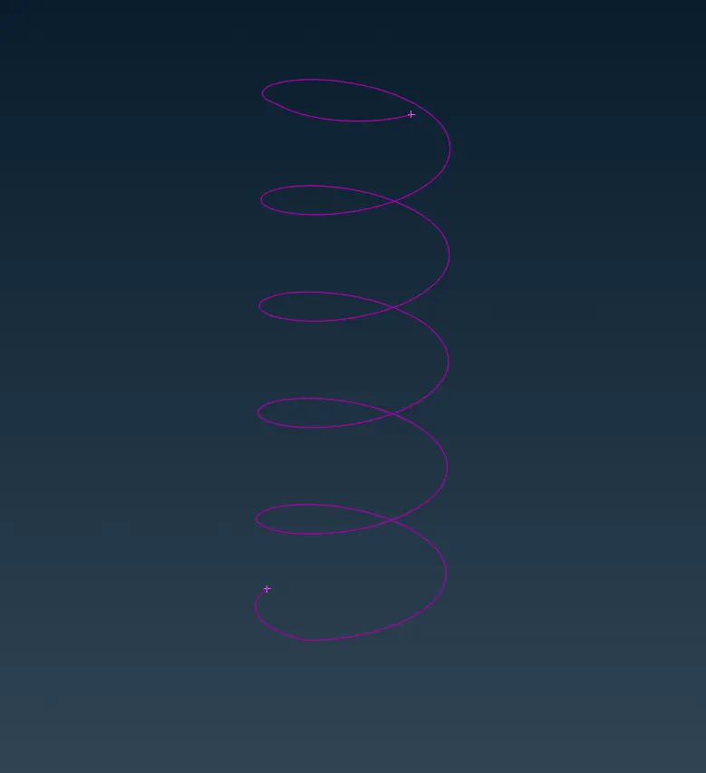
Now we create a COG point Using these Curves
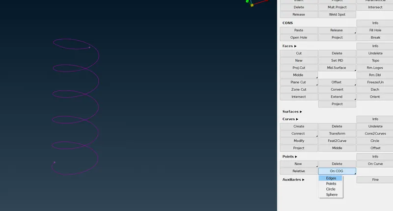
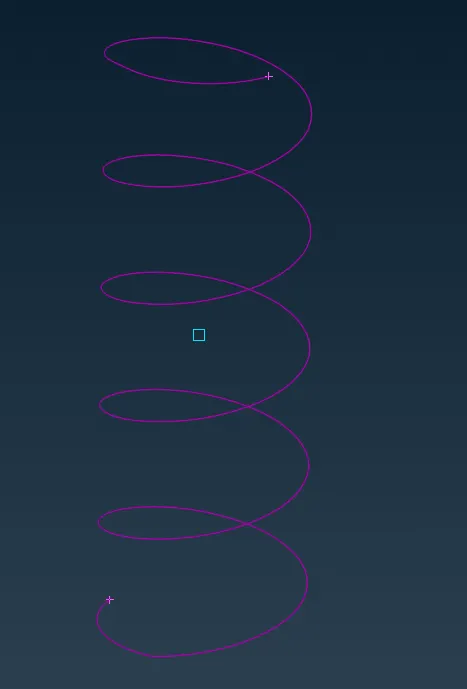
Now we use the CBAR command located in NASTRAN DECK.
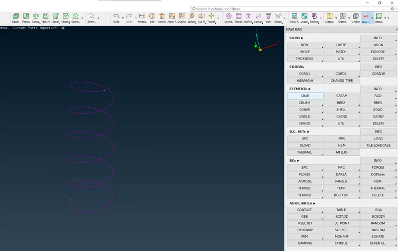
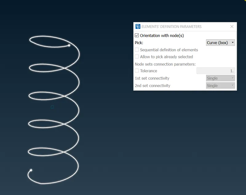
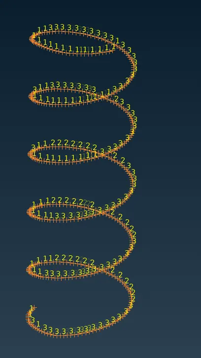
This is how spring is represented in FEA.
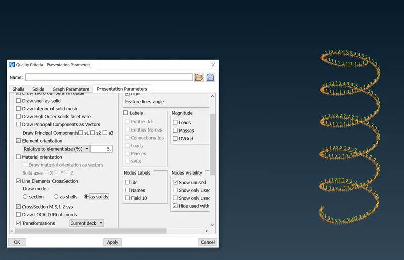
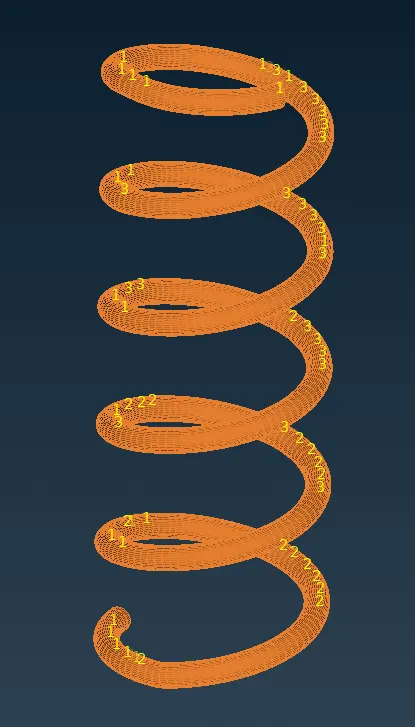
We can draw this 1D Element into solids the same as we draw 2d elements into solids.
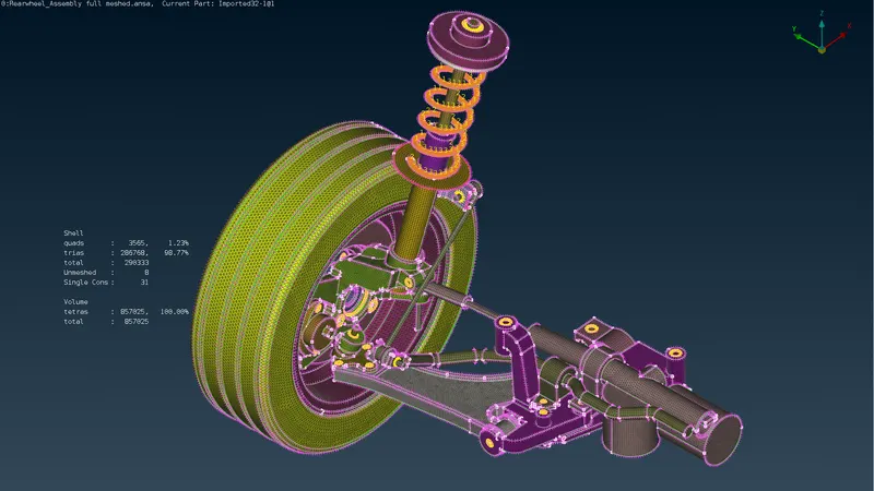
All components meshed.
- Deploy bolt and weld connections.
Now we connect all components by deploying connections.
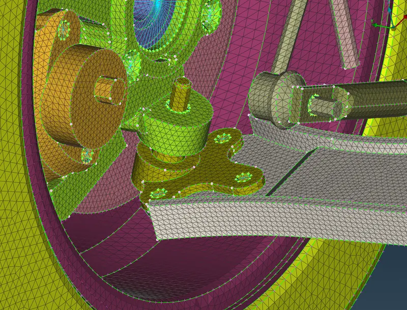
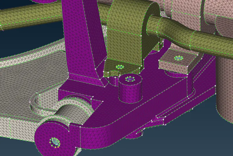
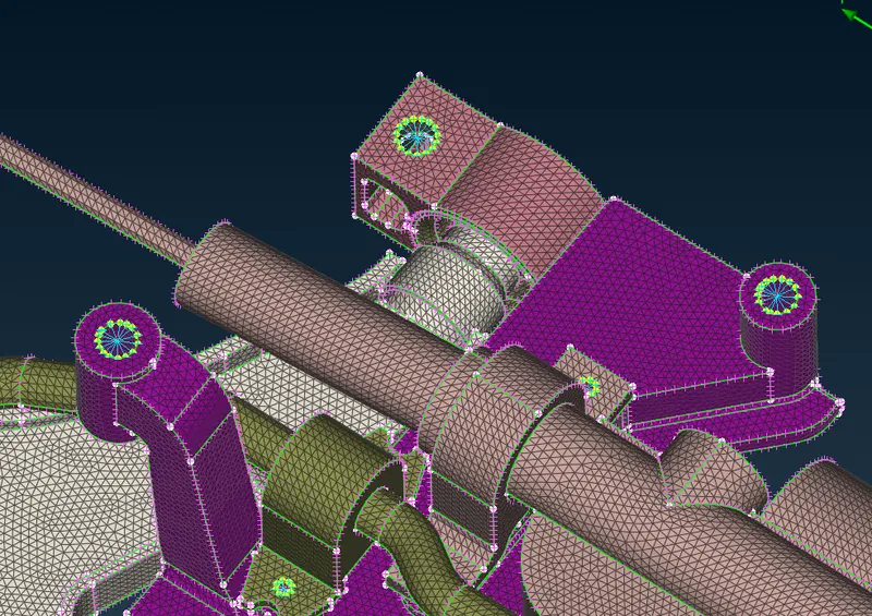
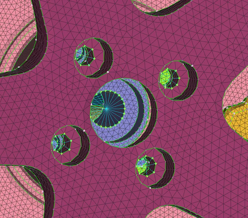
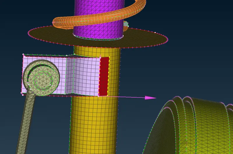
For this bracket, we will deploy OVERLAP SHELL connect to represent the SEAM WELD condition.
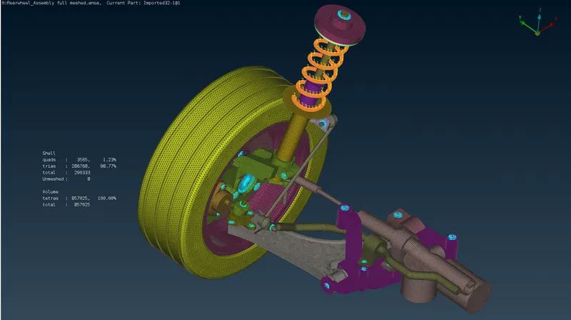
All the connections have been added.
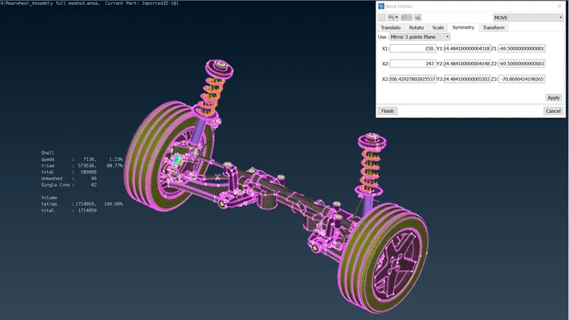
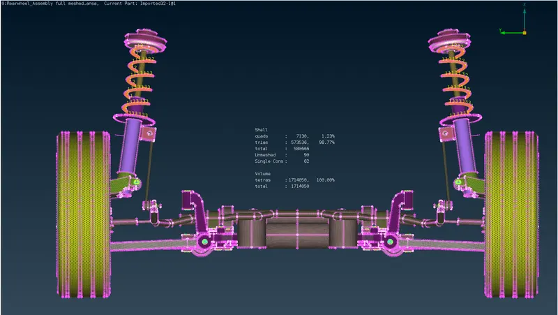
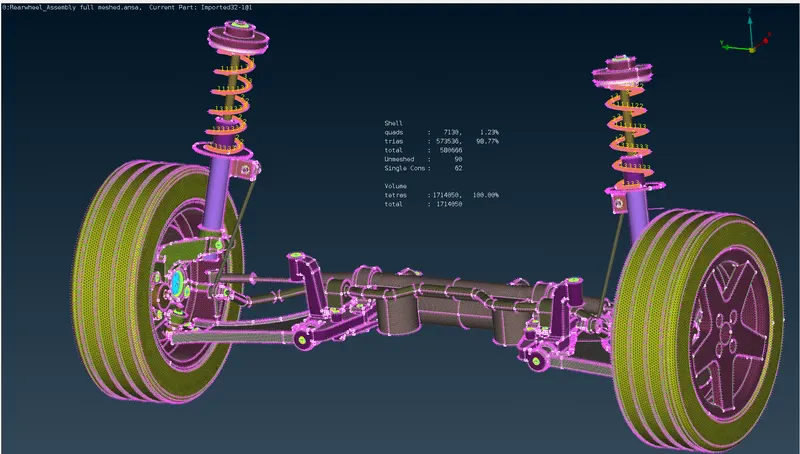
To capture both sides of the suspension assembly we have to copy all the components (CAD, FEA and Connection) and paste them on the other side of the symmetry.
This can be done using TRANSFORM Command.
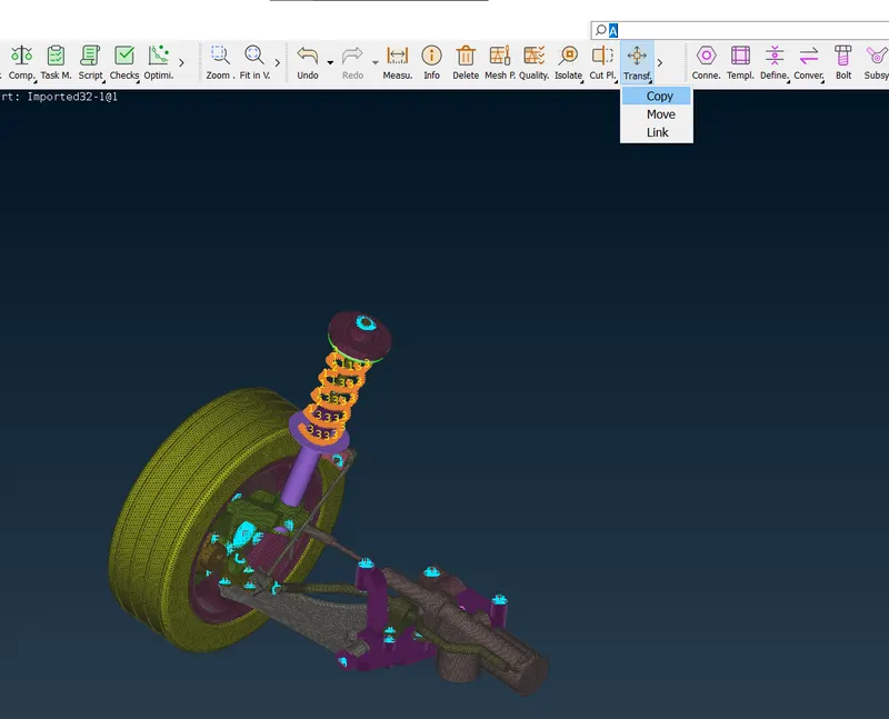
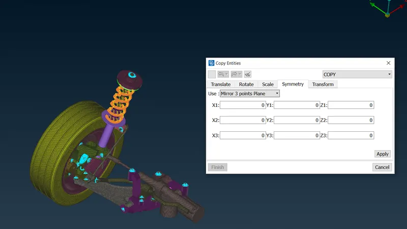
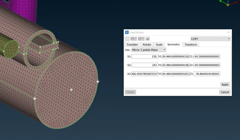
now we select the mirror 3 points to copy everything.
LEARNING OUTCOME:
By doing this challenge I learned,
- How to extract MID-surface of given CAD and generate 2d mesh.
- how to deploy surface mesh and generate the unstructured 3D mesh.
- How to connect components using the RBE2 element.
- How to copy mirror features.
- CONCLUSION:
This concludes the 2D and 3D Mesh with appropriate connections of the suspension assembly.