2D meshing on the Instrumental Panel Substrate using ANSA
Aim:
The aim of this project is to generate an FEA model of a given Instrument Panel Substrate
Objective:
- Analyze the CAD model for any geometry errors. If present, then correct it.
- Extract mid-surface and deploy 2D mesh using the CASTING command.
- Use ALIGN MANAGER command to regenerate failing features.
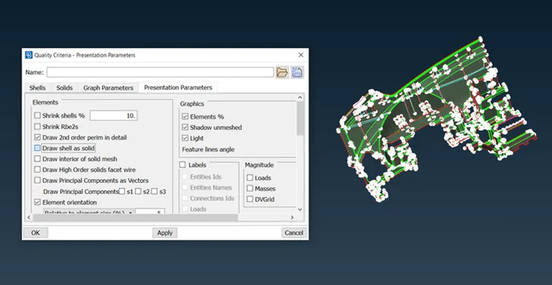
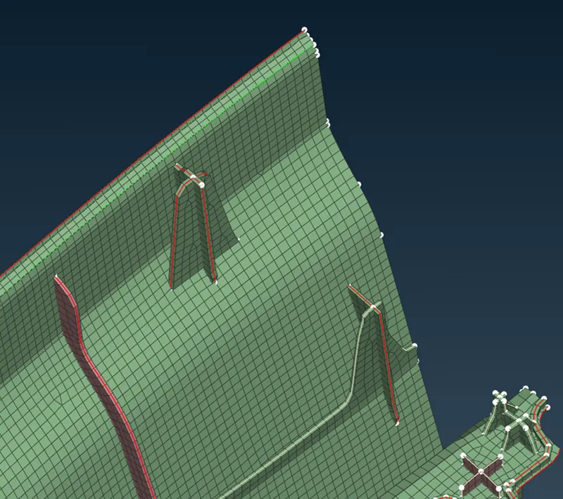
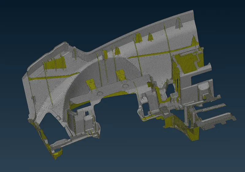
- Draw shell mesh into solid and verify the FEA capture.
Element Quality Criteria for this challenge.
Procedure.
Step 1 is to analyze the given CAD for any geometrical errors.
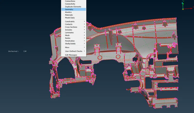
After importing the CAD geometry to ANSA we checked for any geometry error that came with the model. To do so we go to the Check-Geometry option in ANSA.
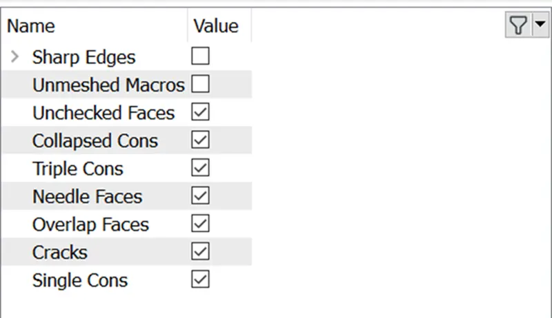
ANSA will check the CAD model over the above-mentioned criteria, and if the model fails, ANSA will prompt any error describing the reason for the error.
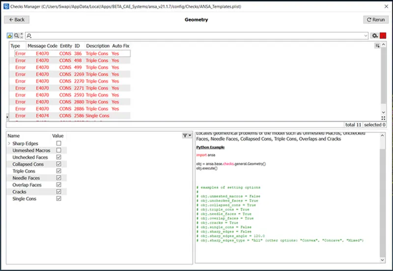
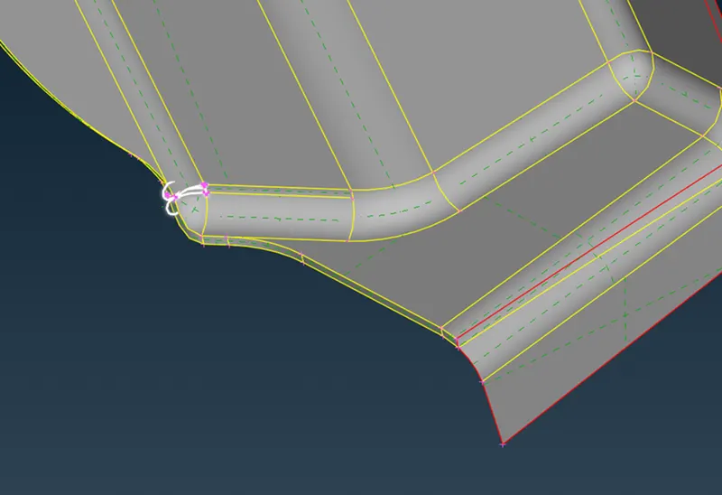
As we executed the geometry check function, we found some errors. Now there are 2 ways to solve these errors:
- Auto fix option that ANSA provides. (ANSA will fix the failing features.)
- Manual fix-User will manually fix the failing faces or Cons.
In our challenge, ANSA was able to auto-fix most of the errors. while some of the errors require manual input.
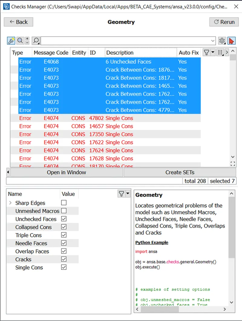
These cracks and unchecked faces have to be repaired manually.
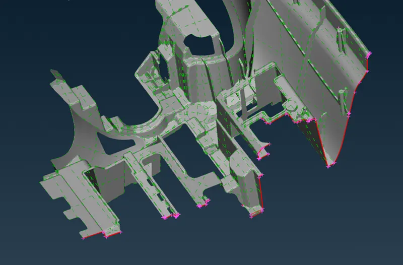
The CAD model given in this project is half of the IP Substrate so your geometry is open at one end. So we have to create new faces to seal off the geometry.
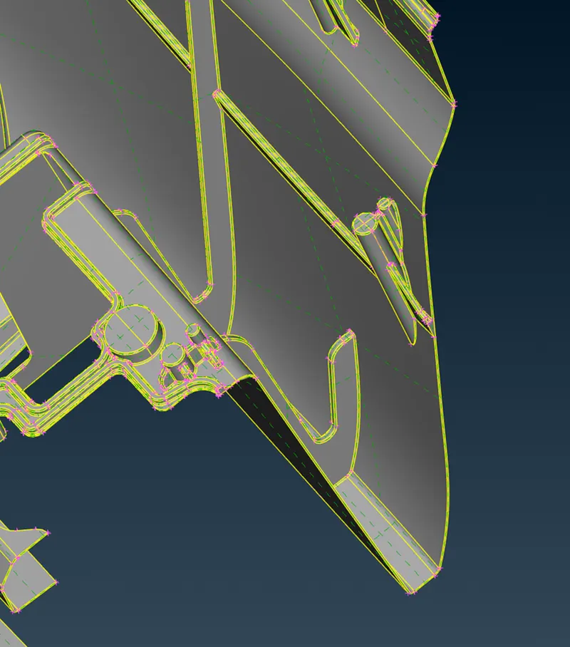
Step 2 to generate a 2D mesh and Mid-surface using CASTING Command.
CASTING Command is located under the MIDSURFACE Command. This command is an automatic command which extracts the mid-surface automatically and deploys 2D mesh automatically.
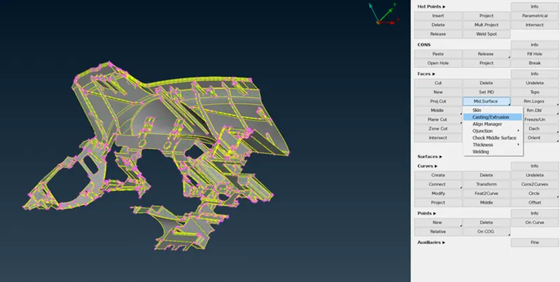
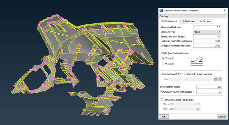
There are some features which are not adequately captured by the CASTING command.
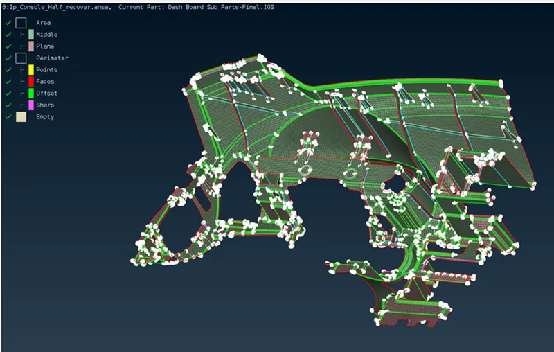
All the dog hose has to be captured by this method.
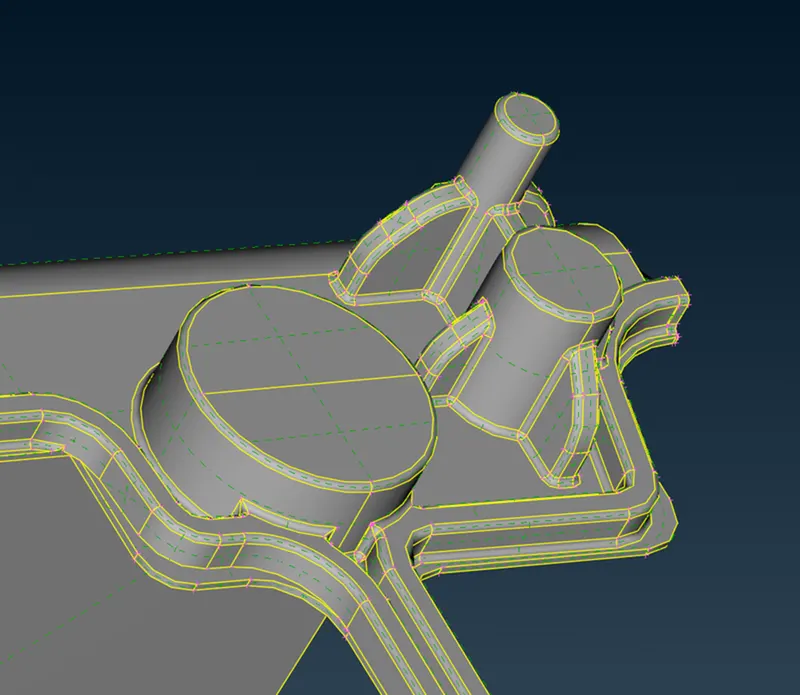
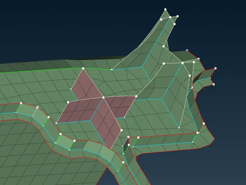
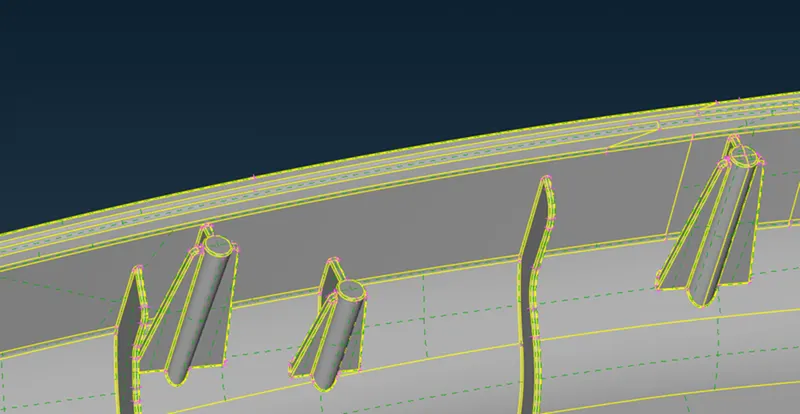
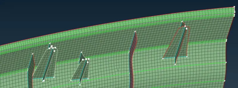
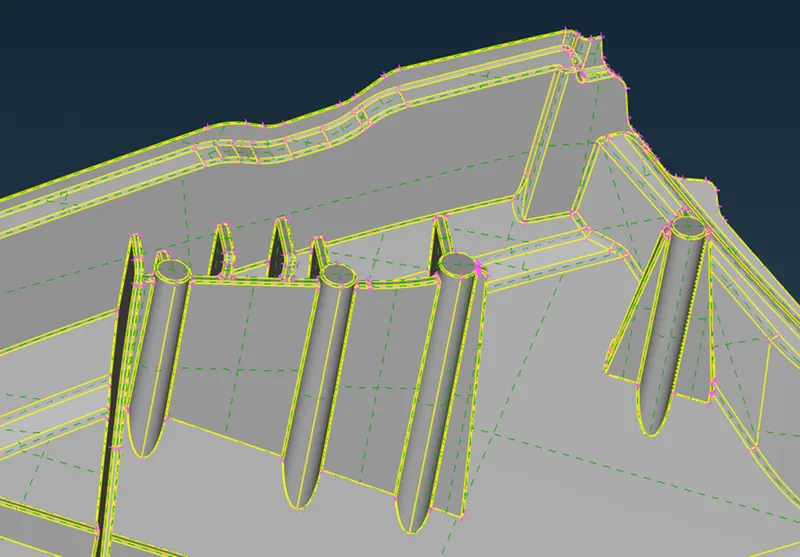
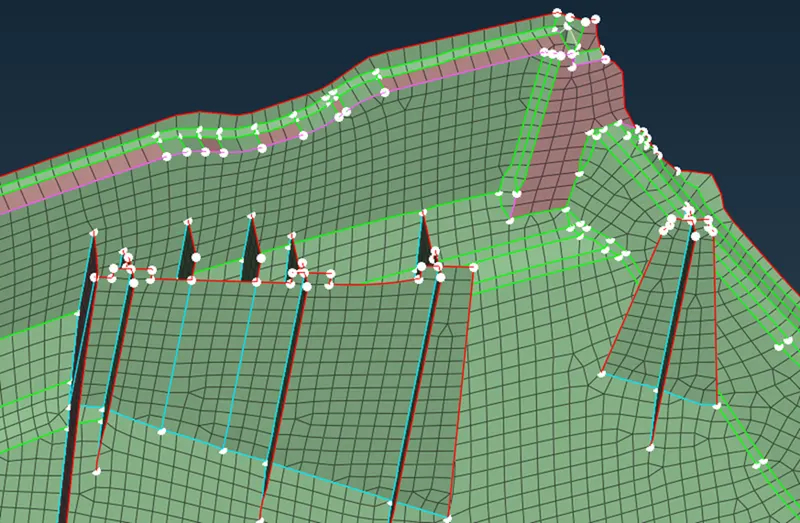
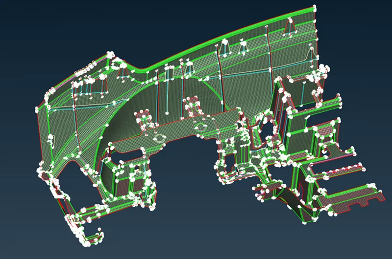
We can fix the miss align that faces the perimeter using ALIGN MANAGER
Step 3 Use ALIGN MANAGER command to regenerate failing features.
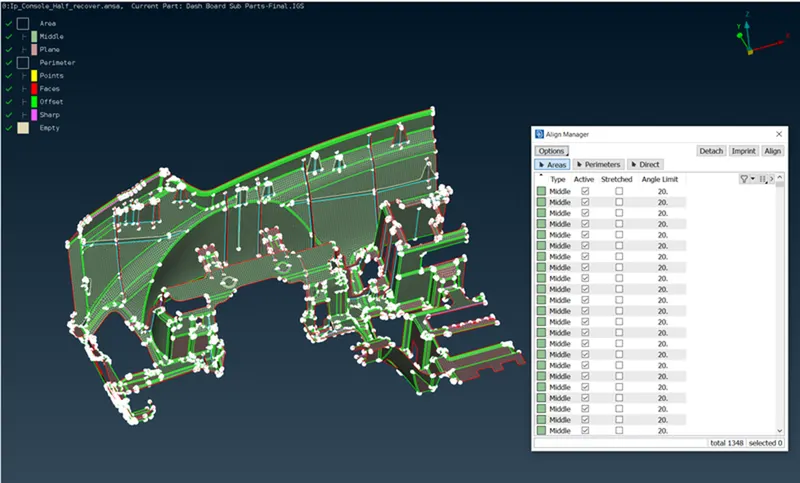
This Dog house and rib perimeter are not defined. we can use Align manager to define it
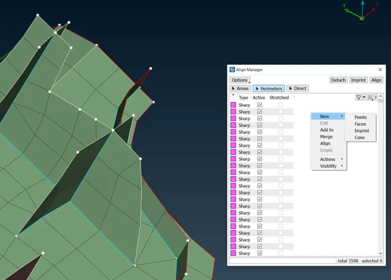
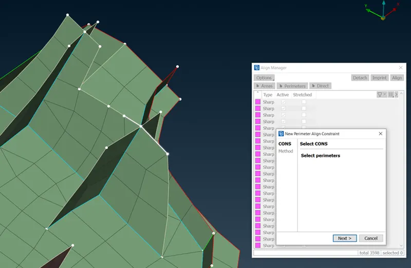
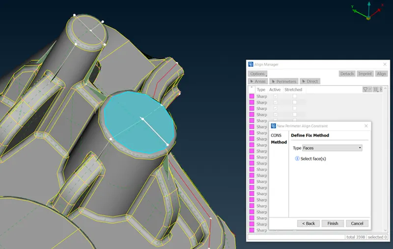
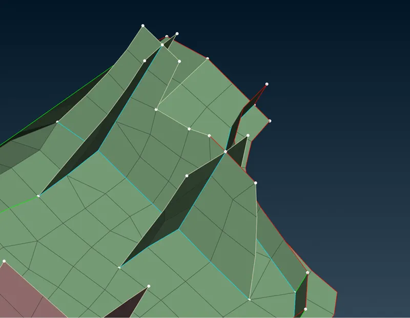
Now, this process of extracting was automatic so the thickness definition has to be done manually. The CASTING command will store the thickness value in the cache memory.
This data has to be converted into a property card. these can be converted using THICKNESS Option in ANSA.
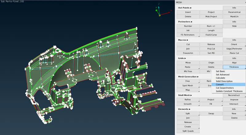
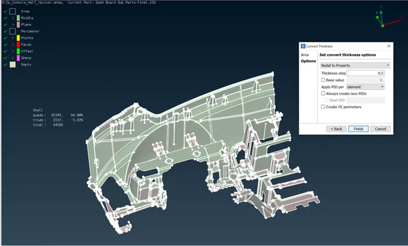
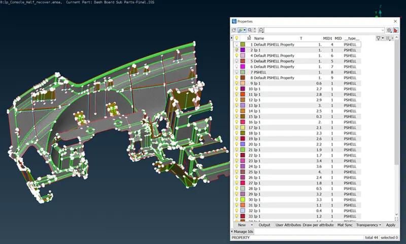
Step 4 Draw shell mesh into solid and verify the FEA capture.
LEARNING OUTCOME:
By doing this challenge I learned,
- How to use the CASTING mid-surface command to automatically generate a mid-surface and deploy 2D mesh.
- how to use ALIGN MANAGER to capture the FEA properly.
- Different ways to manipulate TRIAS in mesh for better results.
- CONCLUSION:
This concludes the 2D Mesh of the Instrument Panel Substrate.