2D meshing for Plastic Bottle Cap using ANSA
Aim:
The aim of the challenge is to generate an FEA mesh of a plastic bottle cap.
Objective:
- Analyze the CAD model for any geometry errors. If present, then correct it.
- Extract mid-surface from each component and fix up some local geometry areas for better mesh flow
- Assign proper thickness to newly created mid-surfaces.
- Apply the element quality criteria and generate mesh from the mid-surface.
Element Quality Criteria for this challenge.
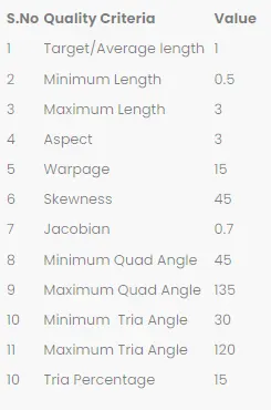
Procedure.
- The first and foremost step is to import and analyze the CAD geometry.
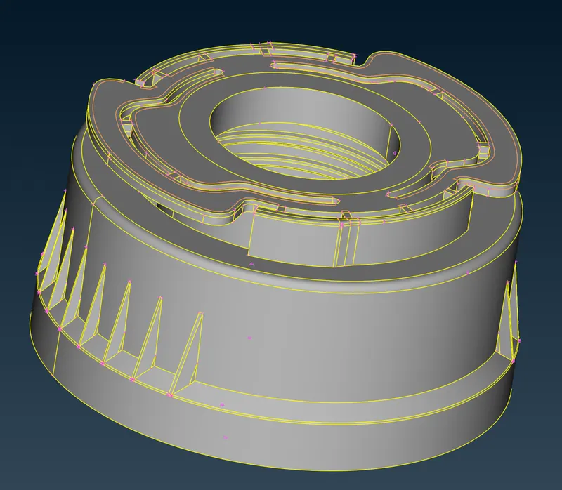
After importing the CAD geometry to ANSA we check for any geometry error that came with the model. To do so we go to the Check-Geometry option in ANSA.
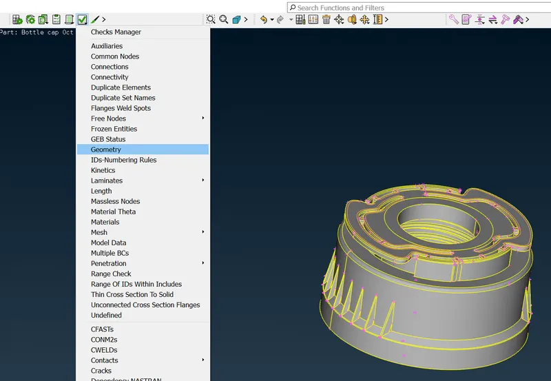
ANSA will check the CAD model over above mention criteria, and if the model fails any of these ANSA will prompt any error describing the reason for the error.
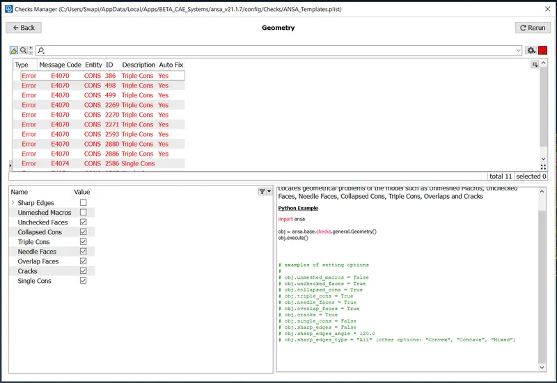
As we executed the geometry check function, we found some errors. Now there are 2 ways to solve these errors:
- Auto fix option that ANSA provides. (ANSA will fix the failing features.)
- Manual fix-User will manually fix the failing faces or Cons.
In our challenge, ANSA was able to auto-fix all the errors.
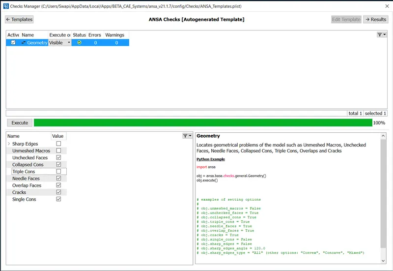
The second step is to extract the mid-surface for each component.
For this challenge, we are taking step by step mid-surface of all the features of the plastic bottle cap. From some features, we can extract mid-surface automatically but for a majority of the features, we will go with manual mid-surfacing.
First, we start with outer features (outer wall), we can calculate the thickness of the features using the MEASURE command in ANSA.
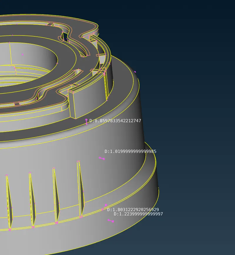
As all the 3 walls with different thicknesses, we go one by one.
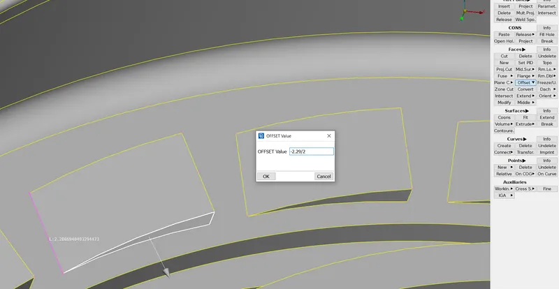
By using the OFFSET command on all the 3 walls individually with the offset value (thickness/2) we calculated before we can extract the mid surface.
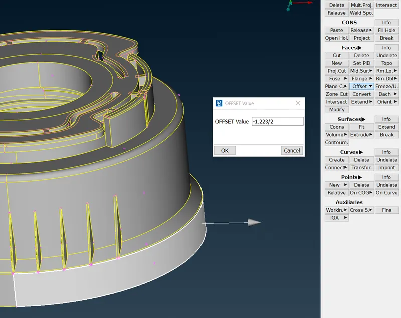
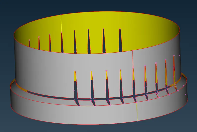
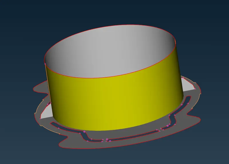
Now we see the two walls are not properly cleaned up (we still have gaps from connected features). We can clan this geometry up by creating construction curves from the top and bottom cons and we can create a new surface and delete the old one (see images for more details).
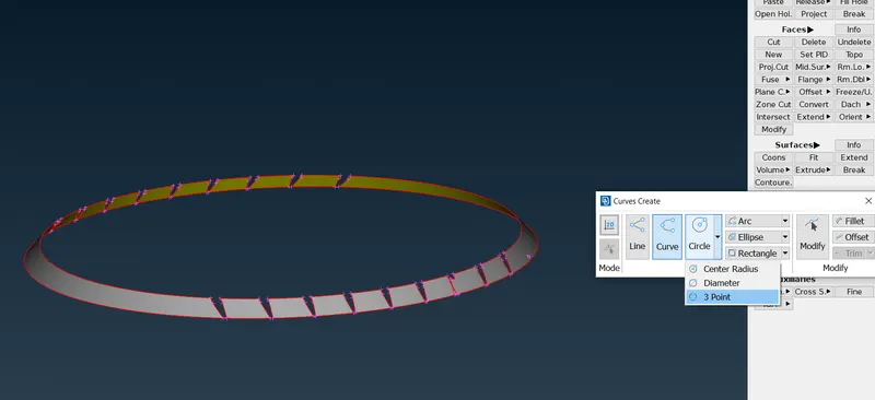
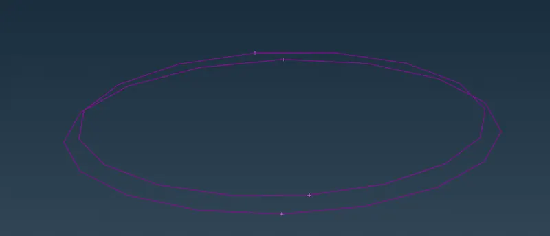
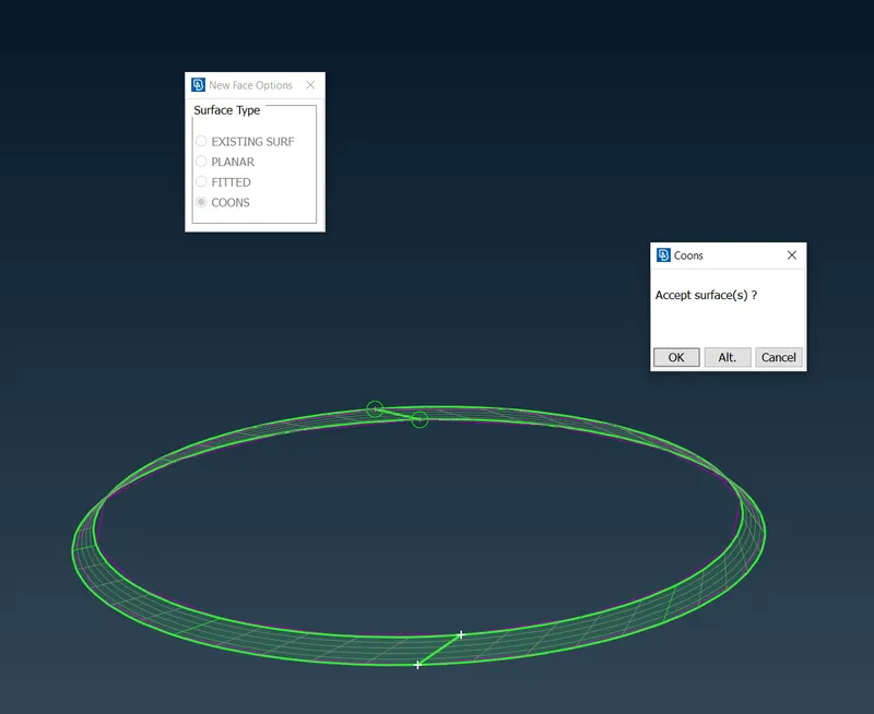
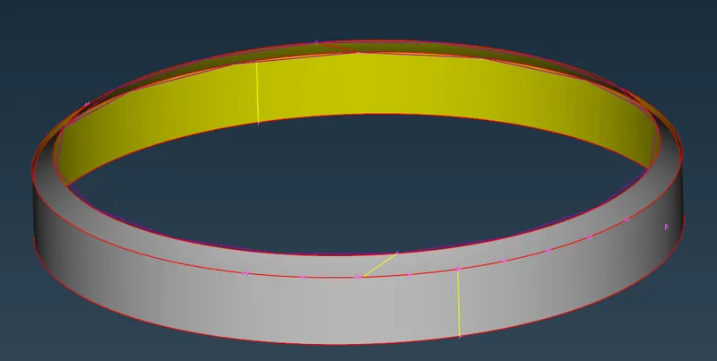
We can Extend and connect all the 3 walls by using EXTEND and INTERSECT commands.
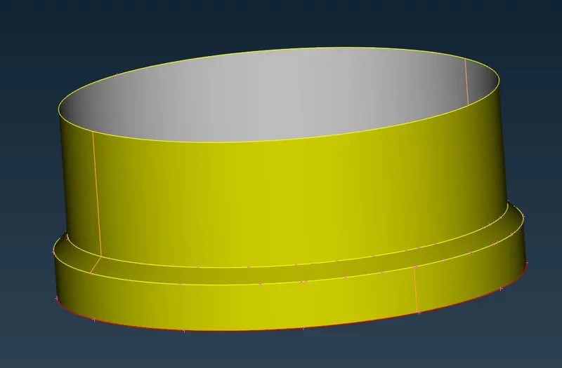
By using the same procedure we can extract the remaining top face and the corner rad.
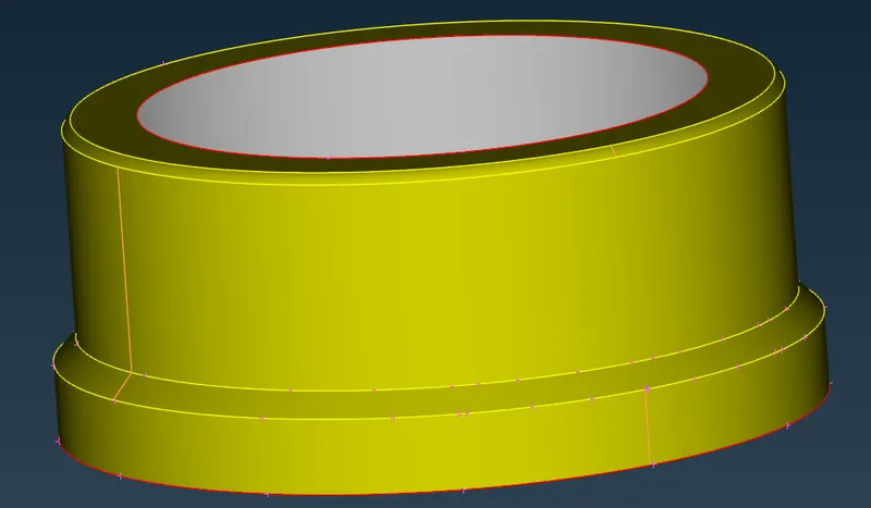
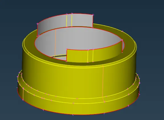
Now we focus on the top outer wall and top surface.
The top outer wall has no uniform thickness (see fig for more detail).
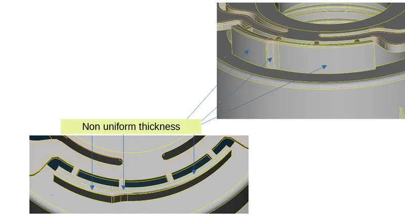 .
. 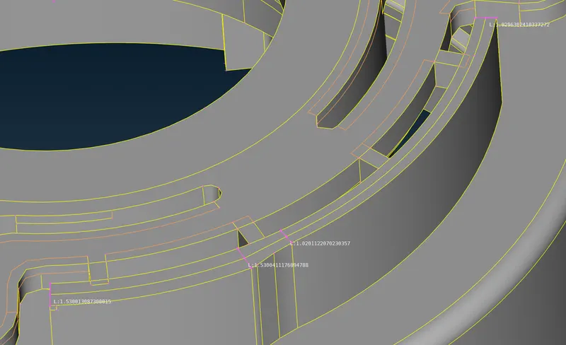
For this situation, we divide the features into 3 parts
- Part 1 has a uniform thickness of 1.53mm
- Part 2 is a transition area.
- Part 3 also has a uniform thickness of 1.03mm
For parts 1 & 3 we can generate mid-surface by using the similar method we used for outer walls, but for part 3 we must create some construction curves and make new surfaces out of these construction curves.
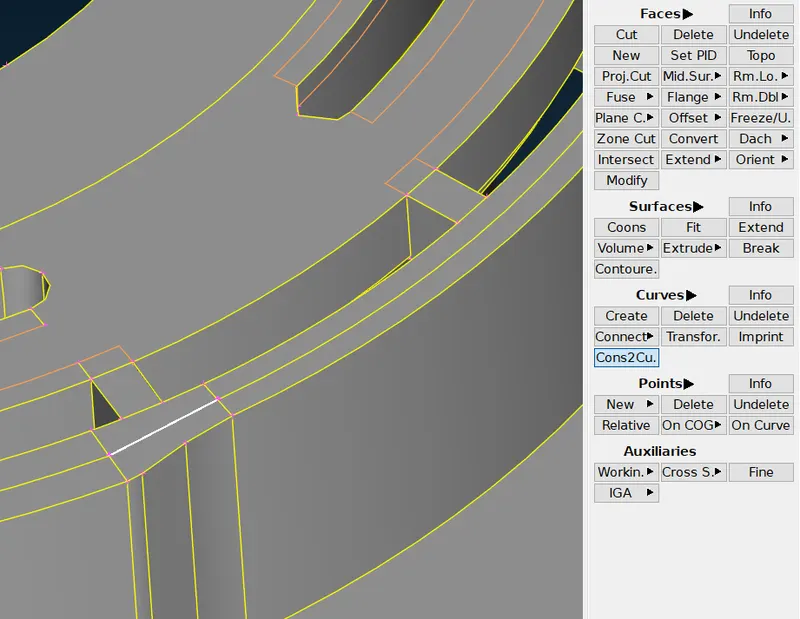
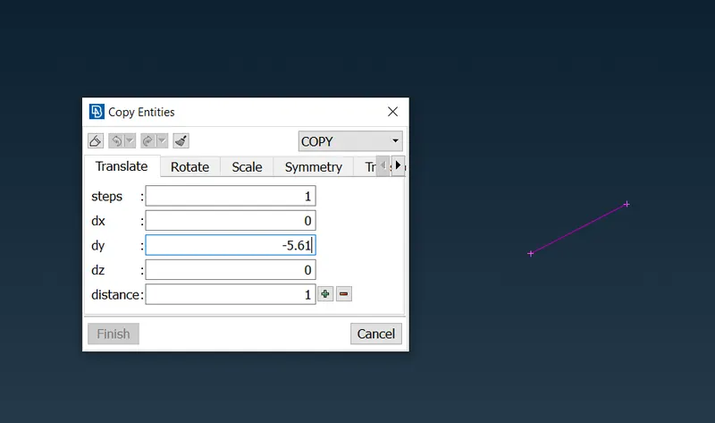
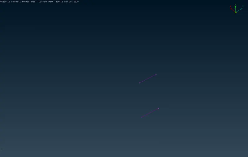
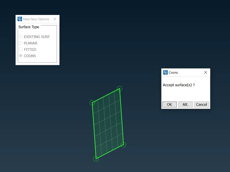
The thickness that we will assign to this transition part will be the average of part 1 and part 2 (T=1.28mm).
We can follow the same procedure on the opposite side top walls.
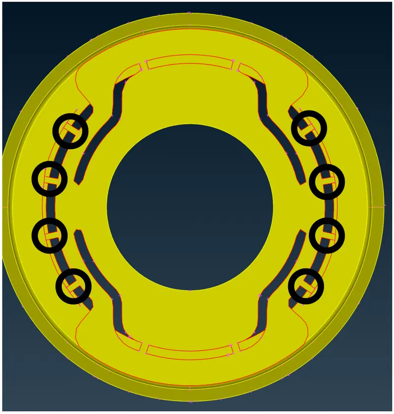
Now we generate mid-surface for the top surface using the OFFSET command. We will also include the connecting features (see fig for more details).
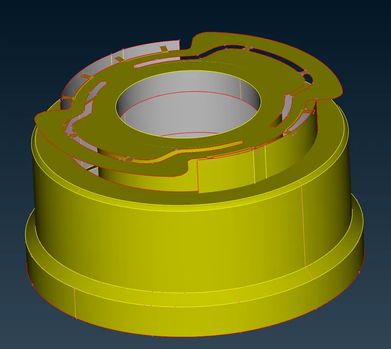
After connecting the outer walls, top surface, and top outer walls (using EXTEND & INTERSECT commands) our mid-surface model will look like this.
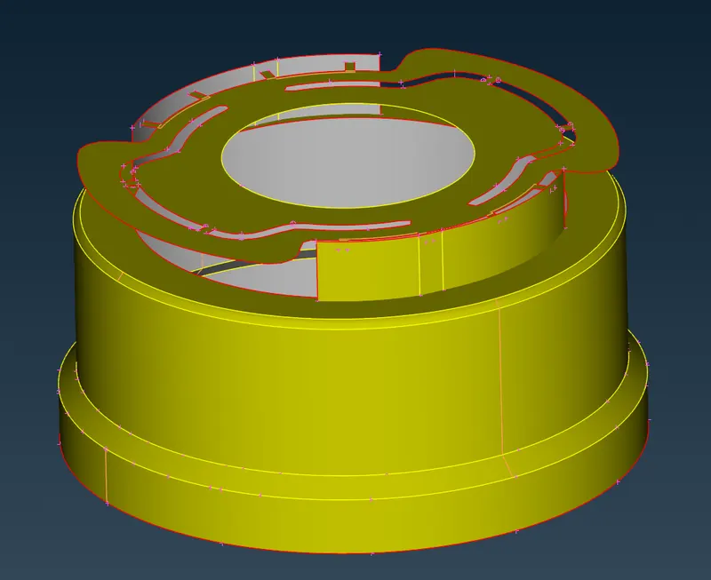
Fig showing top surface/top outer walls and outer walls.
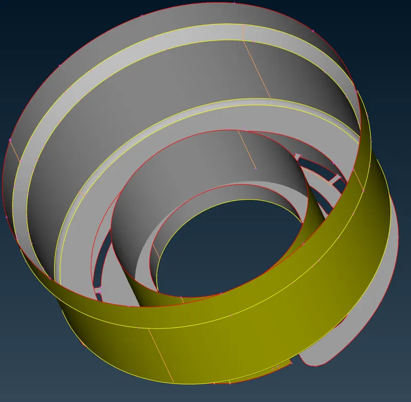
Similarly, we can generate a mid-surface for the inner 2 round walls and 4 inner features and connect it to the top surface.
For the 2 inner ribs, we will be using the MIDDLE command. In this command, we provide two side surfaces (RED & Green) and one surface that represents the thickness of the feature (BLUE) and ANSA will automatically generate a mid-surface for that feature.
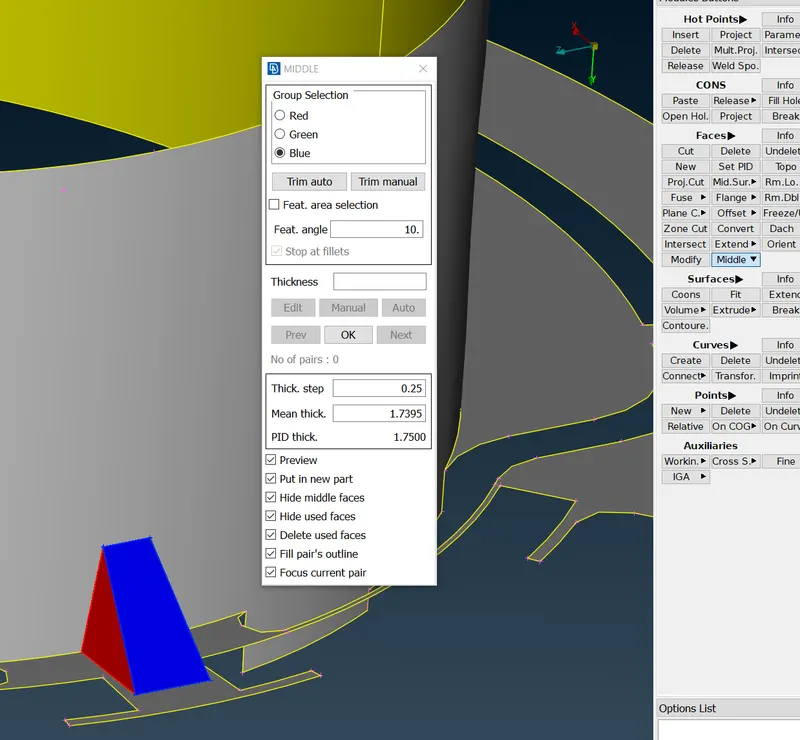
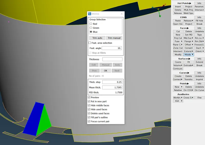
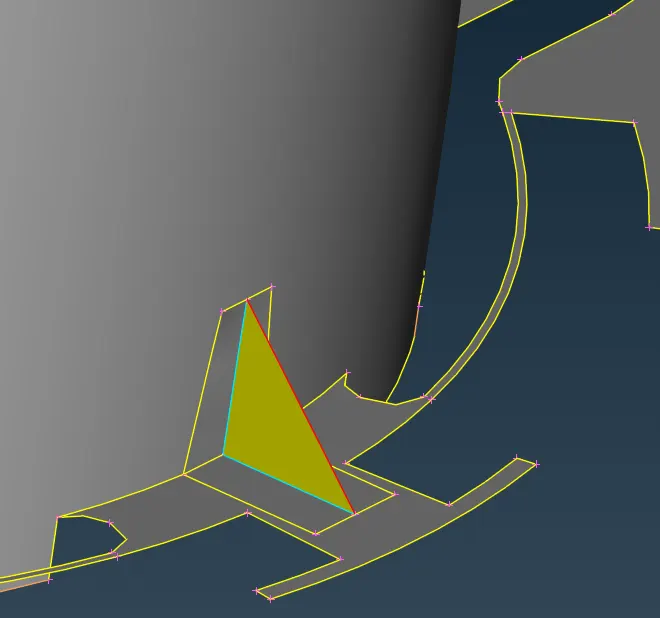
Now we connect the two ribs mid surface with the inner and top surface.
For the mid-surface of the inner teeth, we take the offset of one tooth and copy that mid-surface to all the remaining teeth using the transform command.
The steps to do so are as follows.
- Generate mid surface of one tooth
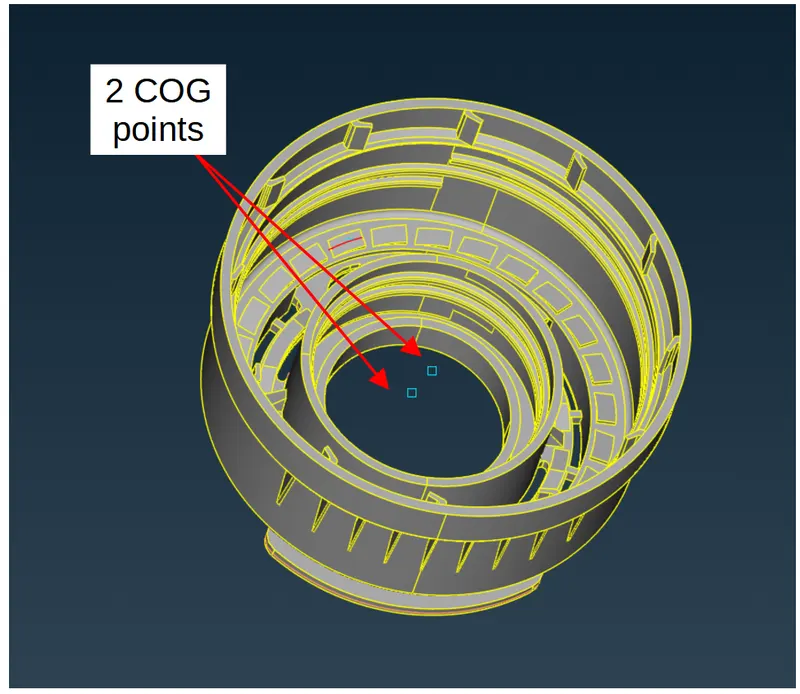
- Create 2 COG points away from each other.
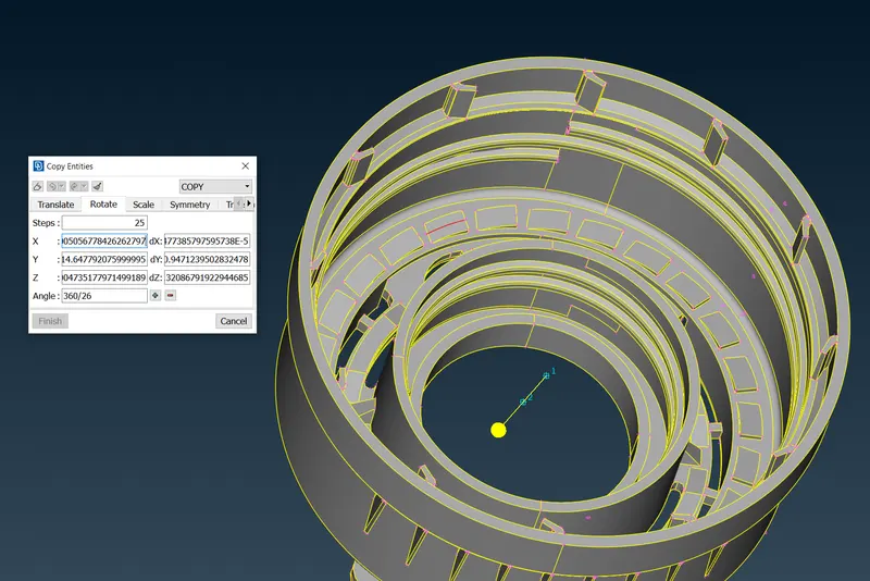
- Use the transform command to rotate/copy the mid-surface by using 2 COG points as the axis.
- Provide the number of teeth and spacing angle between each tooth (In our case it is 360/26 Number of teeth=13.85)
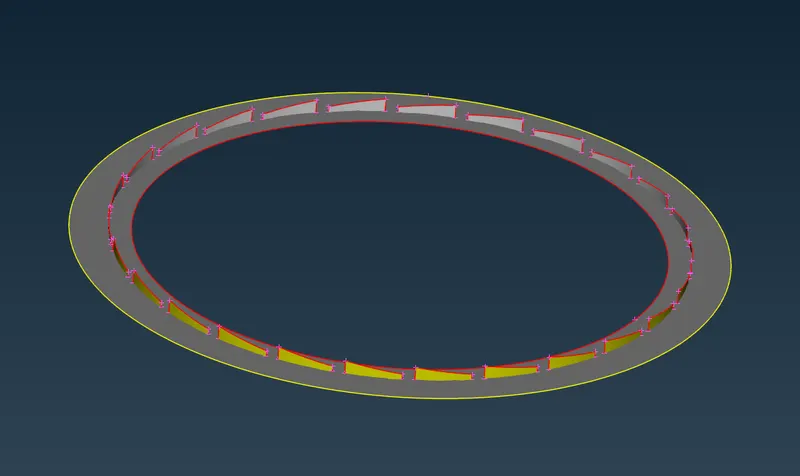
By using the same above mention method we can generate the mid-surface of inner bottom features. Some geometry cleaning must be done on these features for proper mesh flow.
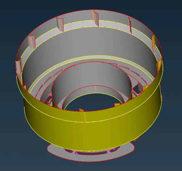
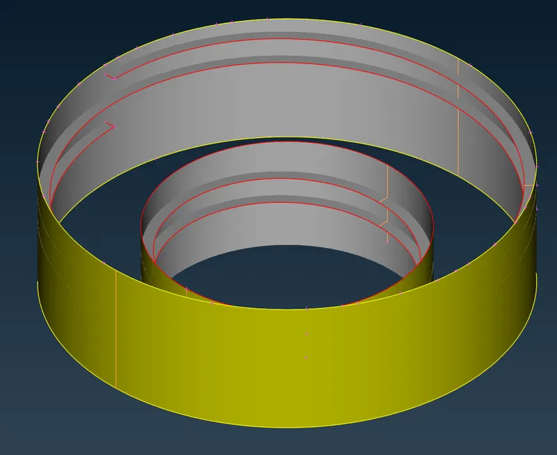
Now we can generate mid-surface for threads. For this, we must create some construction curves using the MIDDLE option present In the CURVE section of ANSA. This command will generate the middle curve of the two reference CONS. Now we can project this curve on the mid-surface outer wall. This will generate a spiral con on that wall, with this con and the spiral curve we created we can generate a new face that face will represent the mid-surface of the threads.
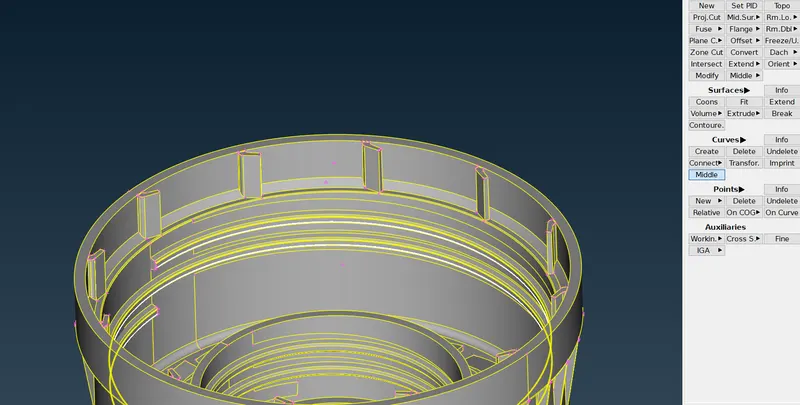
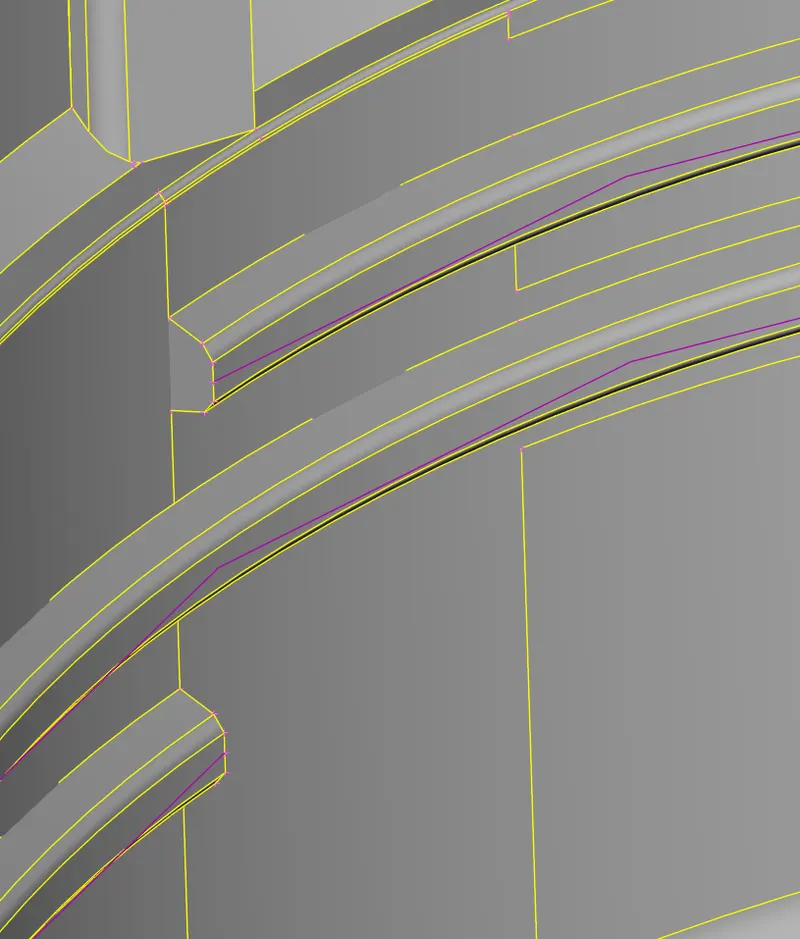
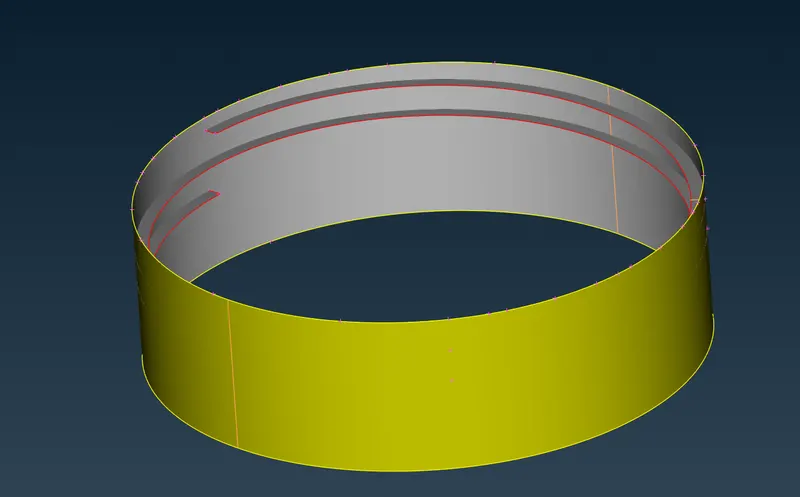
We can use the same process to create a mid-surface for inner threads.
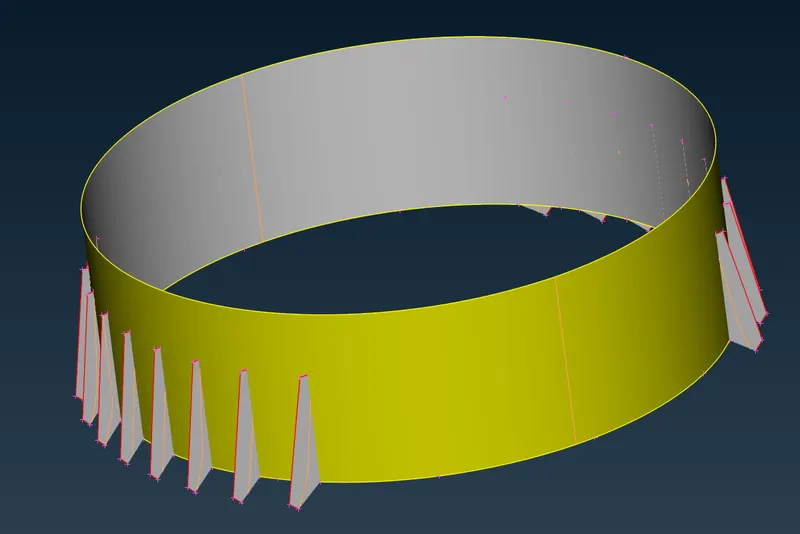
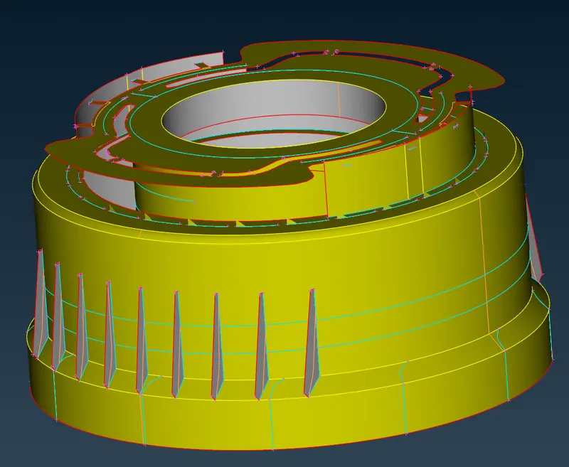
Now the final feature is the outer fins.
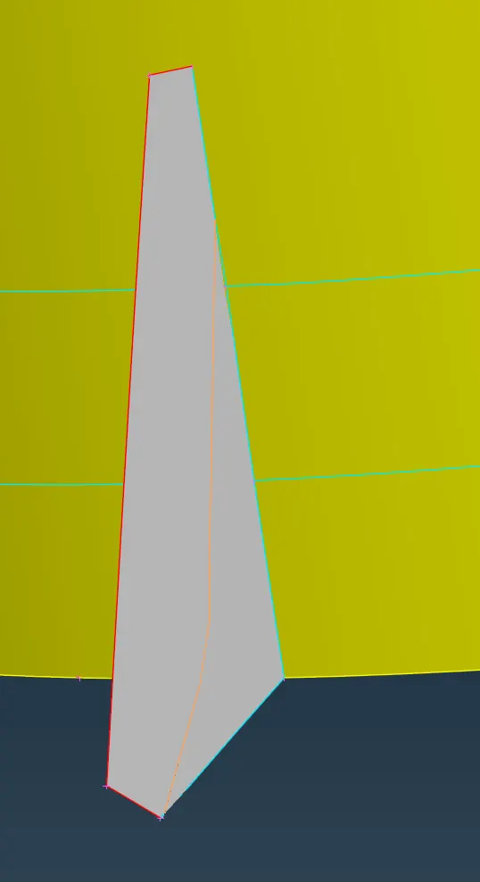
The mid-surface of the outer fins can be generated using a MIDDLE command that we did in the above step.
And this process can be applied to all the outer fins. Some geometry cleaning must be done on the fins for proper mesh flow.
After connecting the fins to the outer wall the model will look like this.
Mid-surface of all the features has been created, now before moving forward with mesh we must do some geometry clean-ups (suppress some unwanted cons, delete extra hotpoints, and simplify some geometry for better mesh flow).
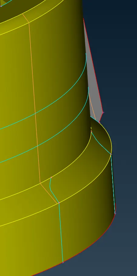
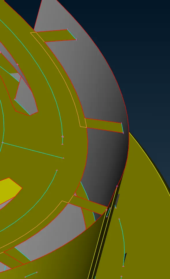
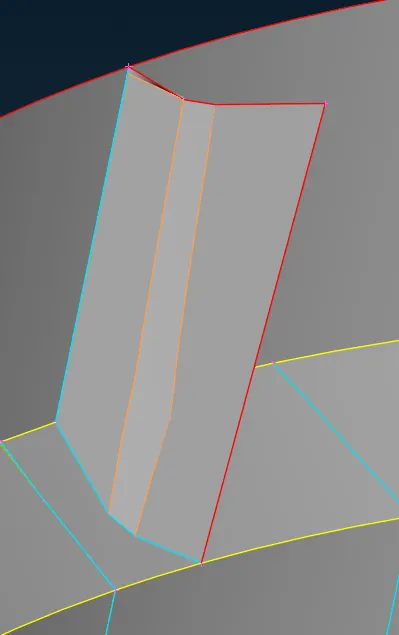
Fig showing suppressed cons and simply filed geometry.
The third step is to assign proper thickness to newly created mid-surfaces.
As we have created a lot of mid-surfaces manually AQNSA will not automatically assign thickness to all the surfaces.
We must manually assign PID to each surface with the proper thickness. (See pictures for more details).
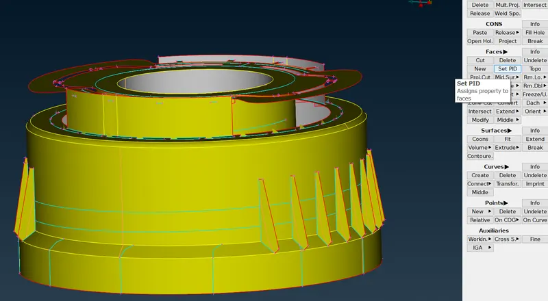
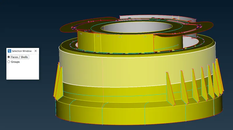
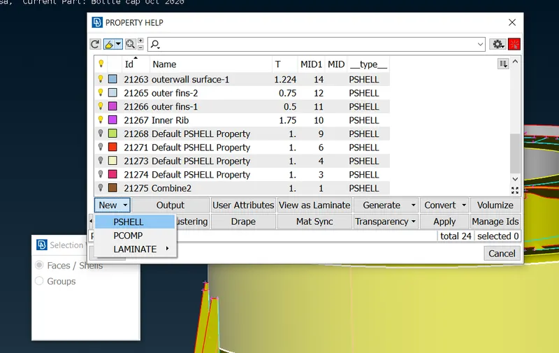
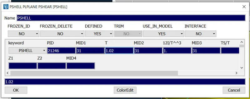
After assigning PID to all the surfaces we are ready to deploy mesh on the mid-surface.
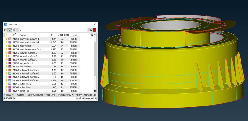
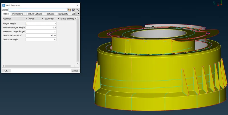
The fourth step is we apply the element quality criteria that are mentioned above. For this, we select the mesh parameter command in ANSA (see fig below)
In this command, we will input our target length of the element to be 1mm and a minimum length of the element to be 0.5mm, and a maximum to be 3mm. We keep mesh type general, mixed selection of elements, and 1st-order elements only.
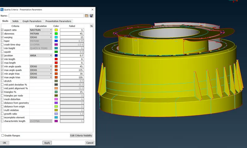
In this command, we will input the element quality criteria that are provided. And in the presentation parameters, we will do the following changes.
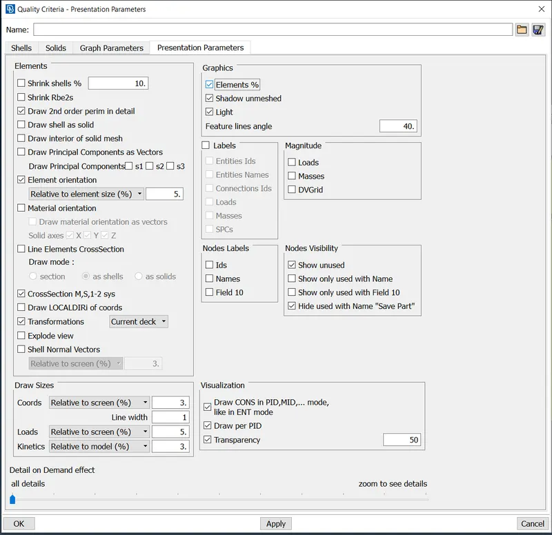
After selecting mesh parameters and quality criteria we will go to the mesh window to apply element length to our component.
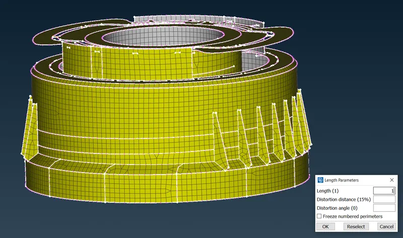
Now Ansa will create points on the surface with 1 mm approx. distance between each point.
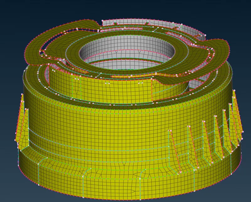
For the mesh we will use the Best Mesh command in ANSA, now this command will automatically select the best suitable mesh for the component.
We go feature by feature and deploy the BEST mesh on the mid-surface we generated.
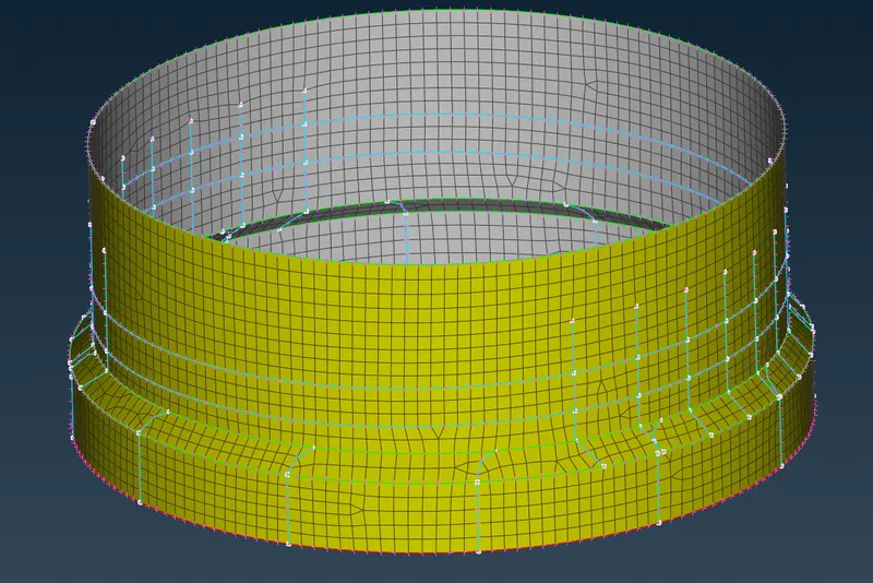
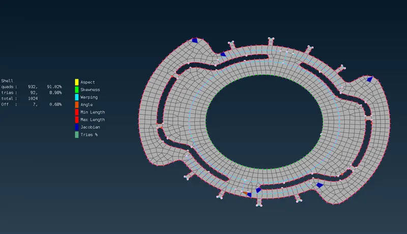
Ansa will deploy the best mesh with some quality errors which can easily be removed by using Reconstruct command.
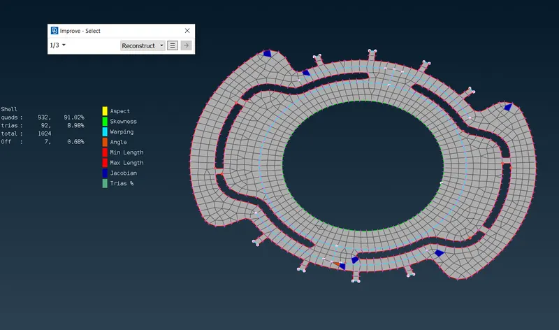
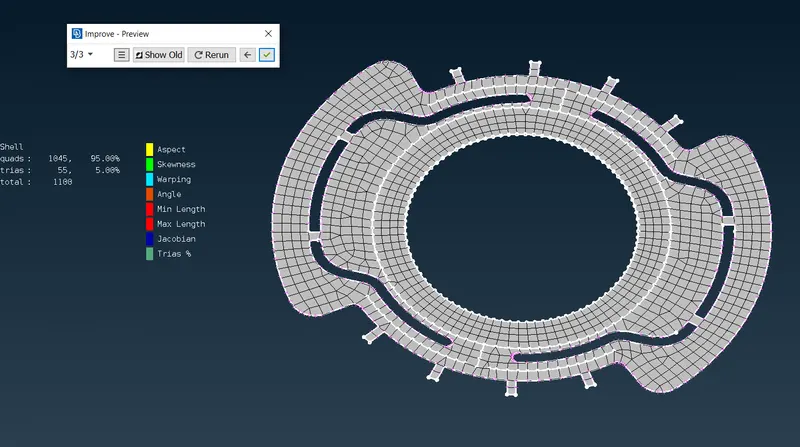
We must remove/relocate some of the TRIA elements that are created near the feature area (hole or outer edge)
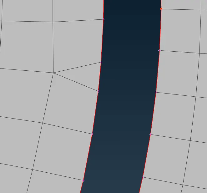
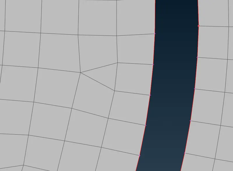
These TRIA elements can be removed/relocated by using the SWAP, SPLIT, PASTE, and JOIN Commands present in ANSA. after some iterations, we can remove the TRIA elements from the features.
we can apply the same procedures to all the components.
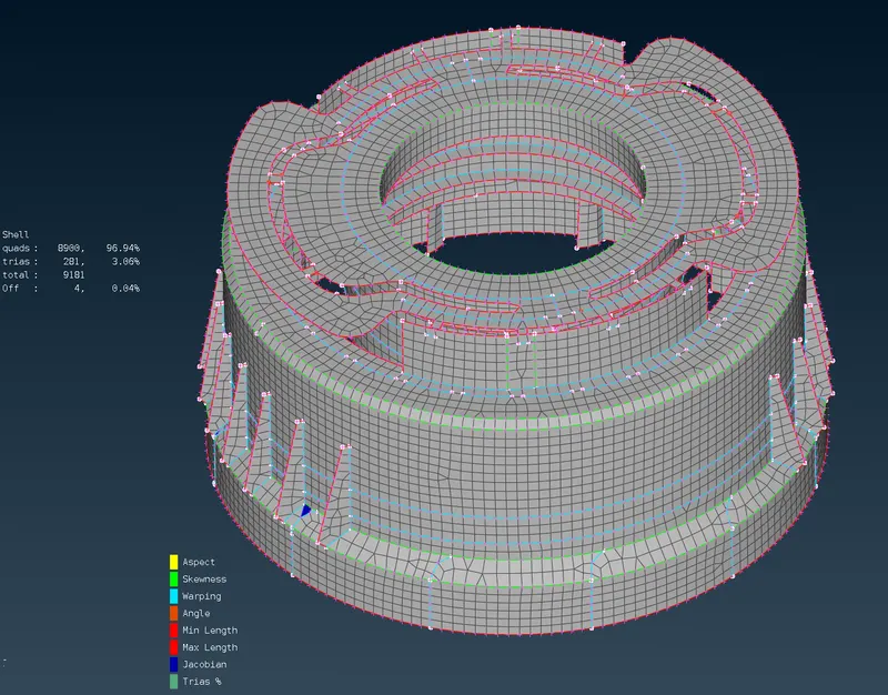
In our case, there will be some quality failure that cannot be removed as it is created by the feature location and geometry but can be minimized to a certain extent. And it is acceptable
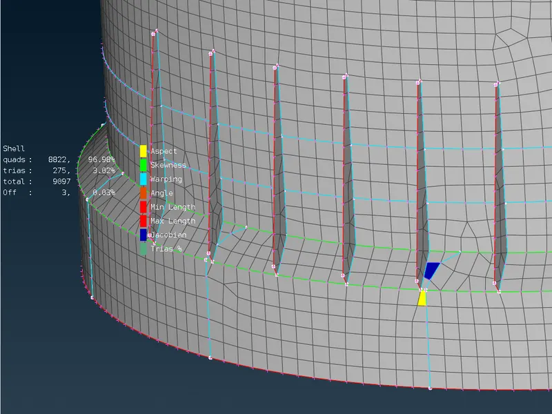
All the components with proper mesh flow (%QUADS- 96.84 %TRIAS-3.02 %OFF-0.03)
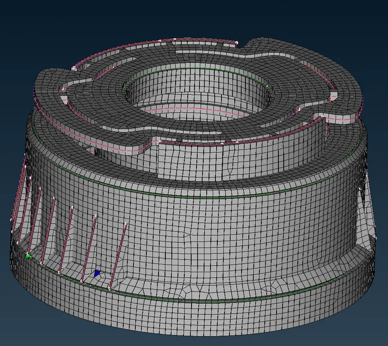
Finally, we draw shells as solids
- LEARNING OUTCOME:
By doing this challenge I learned,
- How to fix geometry by creating construction curves and converting them to new faces.
- How to extract a mid-surface of a feature with varying thickness.
- Different ways to manipulate TRIAS in mesh for better results.
- CONCLUSION:
The plastic bottle cap with properly extracted mid-surface has meshed with .03% OFF elements and good mesh flow.