1D Element Creation Using HyperWorks
Aim:
The aim of the challenge is to understand how 1D elements are created and connected in HyperWorks.
Objective:
For this challenge, we have 3 tasks.
- Using the given model extract mid-surface using HyperWorks.
- Generate a 2D mesh on the mid-surface.
- Create various 1D elements with a given cross-section and DOF using HyperBeam.
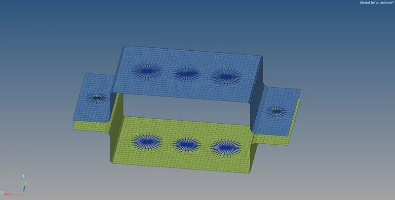
Given Data.
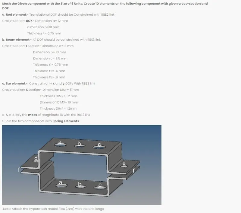
Procedure:
- Extract Mid-surface from the given bracket.
First, we import the CAD model into HyperWoks.
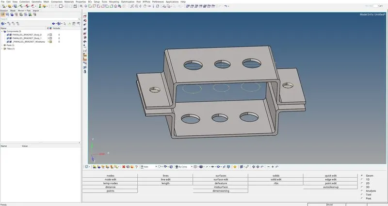
The Import part geometry looks good.
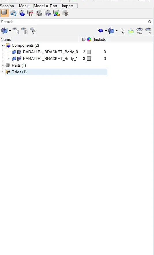
We have 2 components of the bracket.
Now to extract Mid-surface from the CAD we will use the MIDSURFACE tool under the GEOMETRY option.

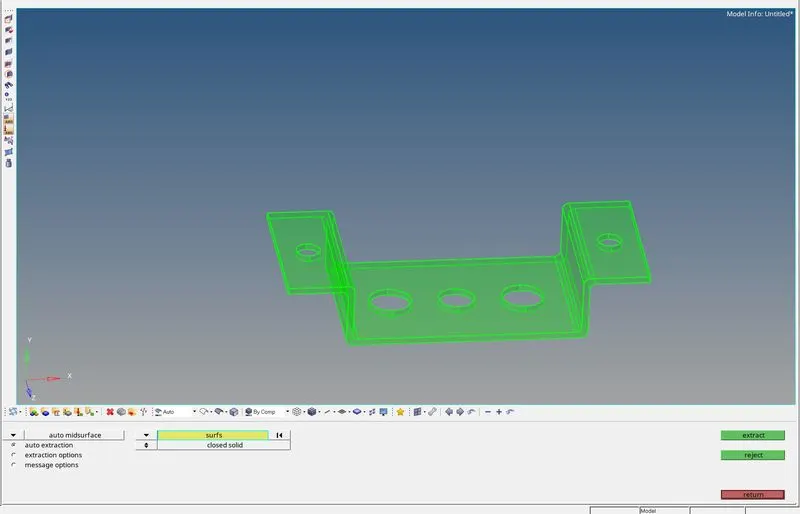
To extract mid-surface we have multiple extraction options.
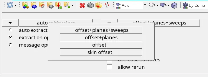
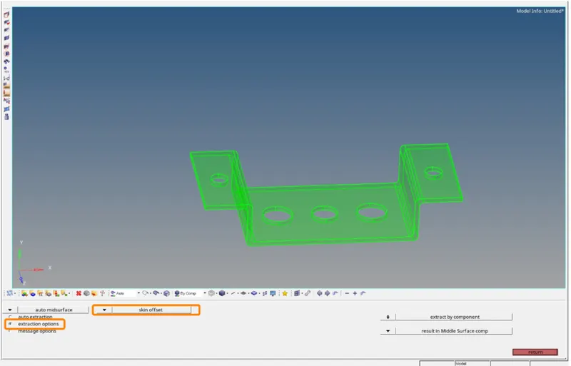
For this component, we will be using SKIN OFFSET
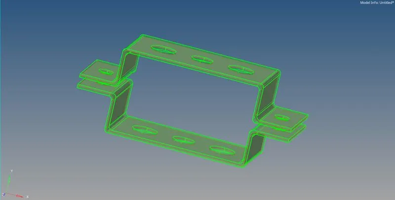
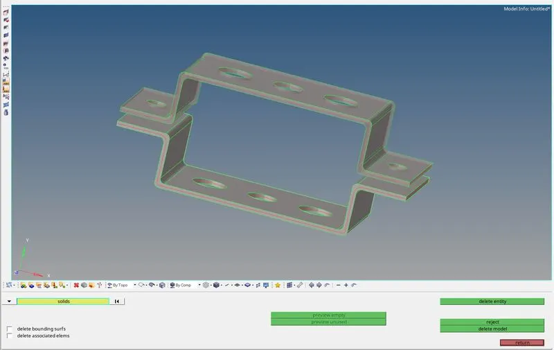
After extracting the mid-surface from both components.
HyperWorks will 2 new separate components for the mid-surface.
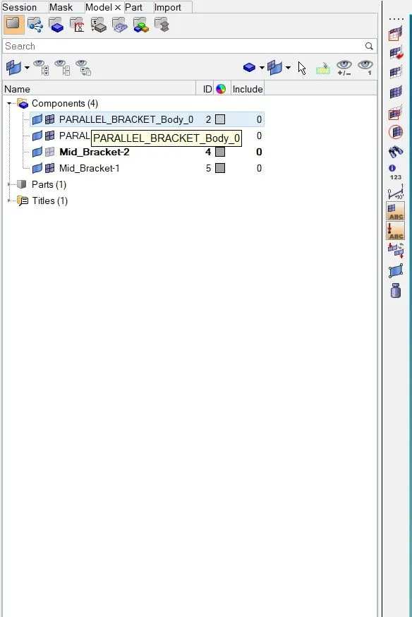
Now we can delete the slid components.
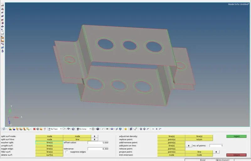
Now before deploying 2D mesh we can create Washer Split on the holes.
- Deploy 2D mesh on the Midsurface.
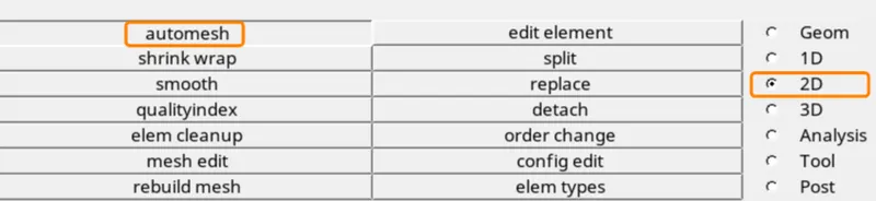
To deploy 2D MESH on the mid-surface, the AUTOMESH tool can be used.
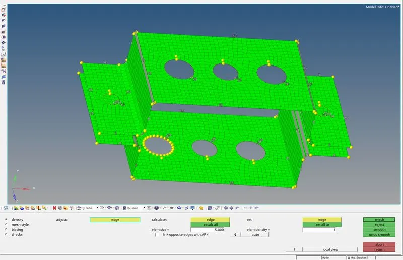
We will use the element size of 5mm.
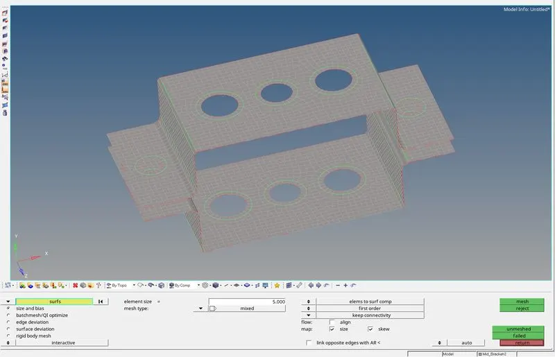
This mid-surface with 2D mesh has no property or material associated with it.
We can create the new material and property card using the following option.
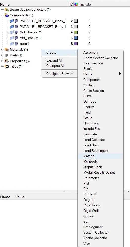
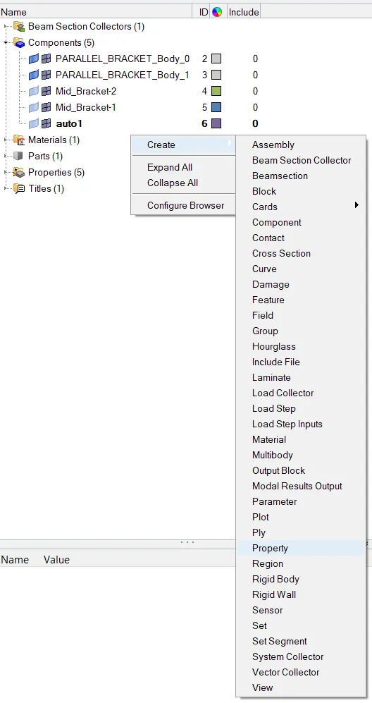
And for the material, we'll use Steel.
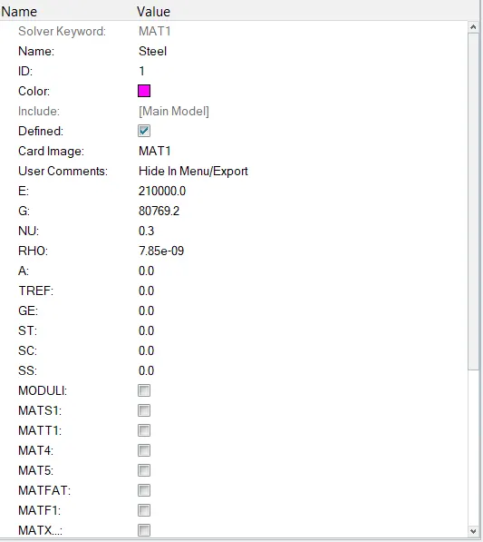
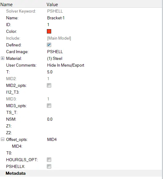
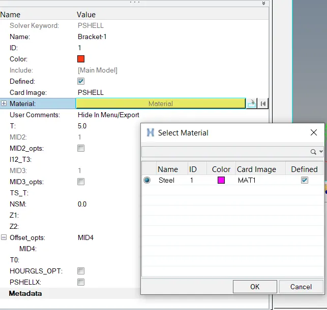
We will input the thickness and Card image as 5.0mm & PSHELL. For material, we will select Steel.
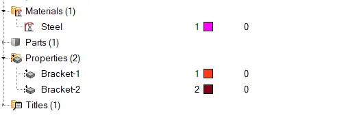
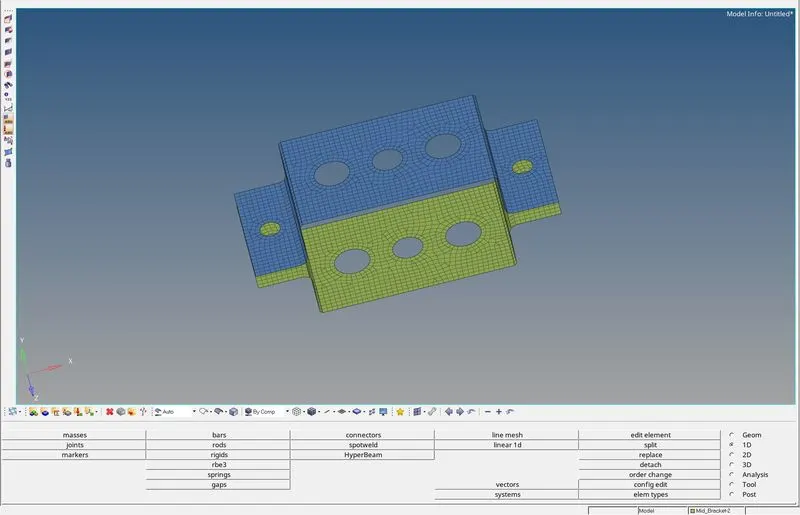
Similarly, we will create another property for the other half of the bracket.
- Create 1D elements as per the given data.
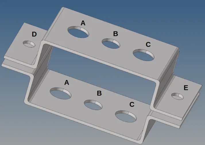
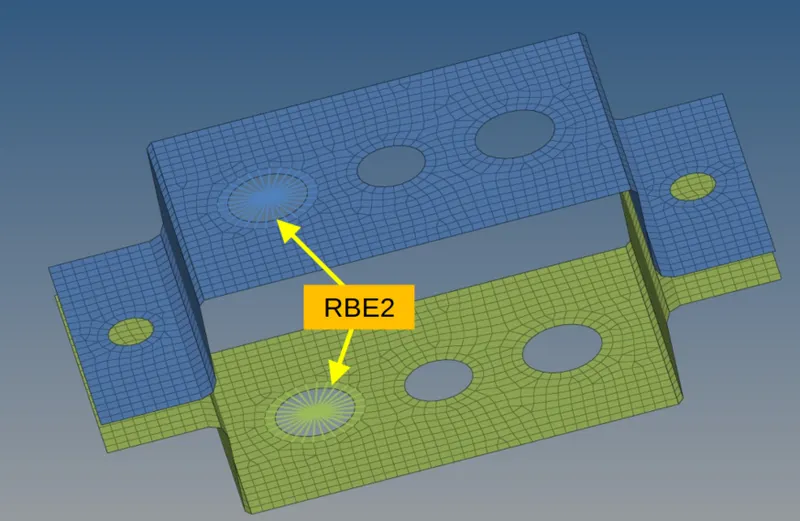
FOR HOLE A - Translational DOF should be Constrained with the RBE2 link
FOR HOLE B - All DOF should be constrained with the RBE3 link
FOR HOLE C - Constrain only x and y DOFs With RBE3 link
FOR HOLE D & E - All DOF should be constrained with the RBE3 link
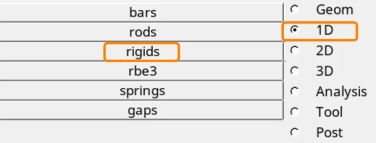
To deploy the RBE2 element on hole A we will use the RIGID tool under the 1D option.
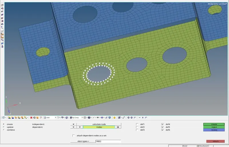

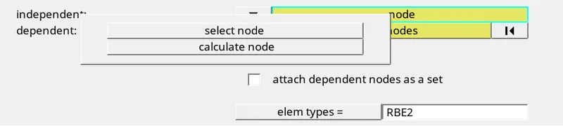
since we are adding an RBE2 element on the hole feature we will select the Multiple node option and the Calculate node option.
We will select all the nodes at the hole periphery and also the second row of nodes
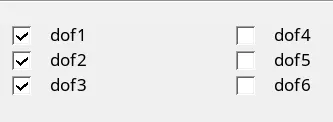
As we have to constrain all the translation DOF we will only select DOF 1,2 & 3.
(DOF 1,2 & 3 represent 3 translations DOF and DOF 4,5 & 6 represent 3 rotational DOF).
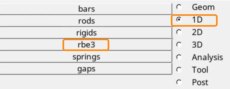
Now for hole B, we have to create an RBE3 element.
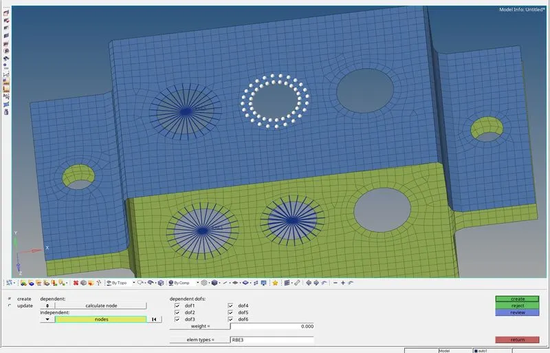

For hole B we have to constrain all 6 DOF.
Using this method we will deploy the rest of the elements.
As per the challenge, we have to connect holes A, B & C with BAR, BEAM & ROD elements. Before creating this element we will define the core section of the elements.
In HyperWorks, the HyperBeam tool is used to define the crosssection of the 1D elements.
HyperBeam can be accessed by 2 methods, which are as follows;
Method-1
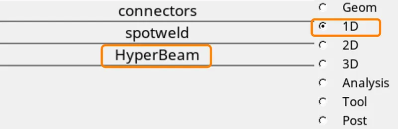
Method-2
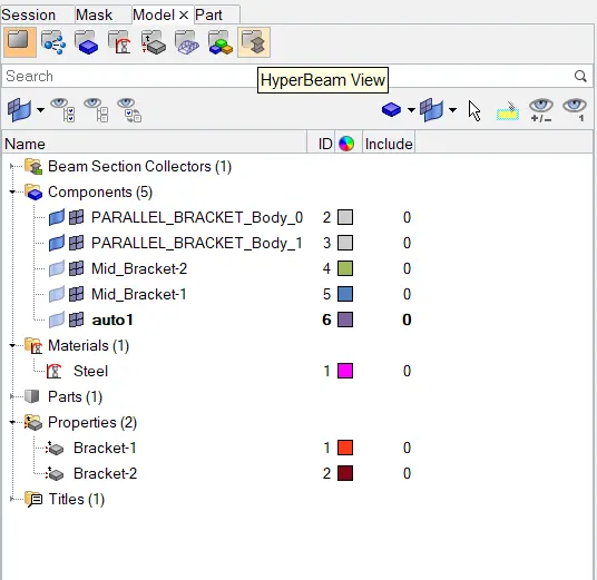
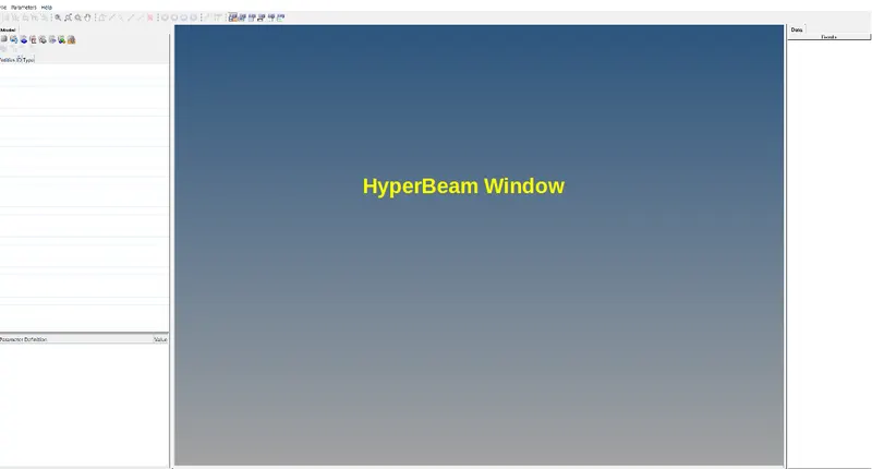
Now in this window, we have to create a new element.
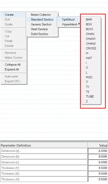
This list consists of pre-define Shapes of elements.
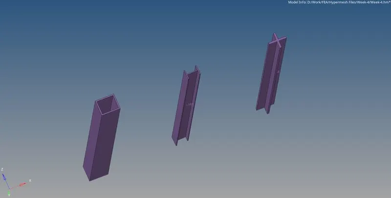
For our challenge, we need an I section, an X section & Box section.
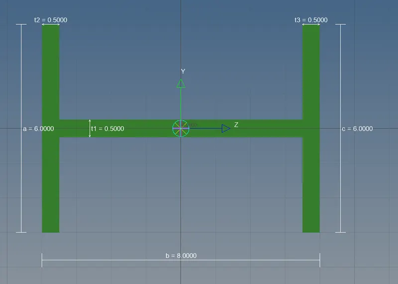
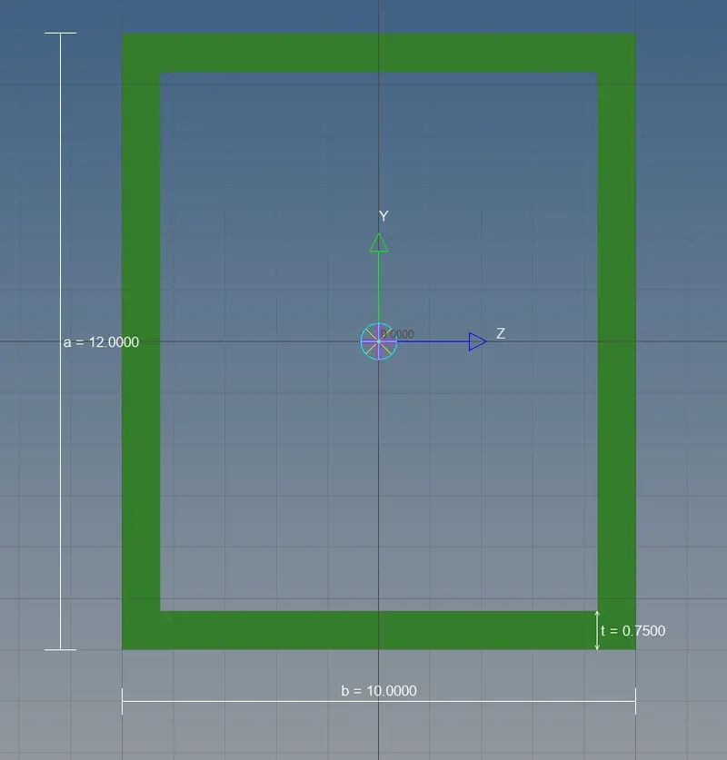
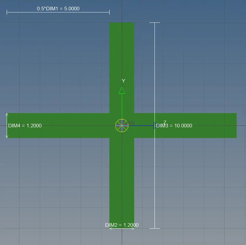
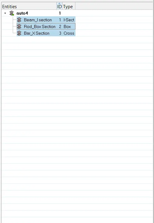
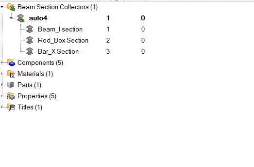
now we have to create a Property card for these new elements with material as STEEL
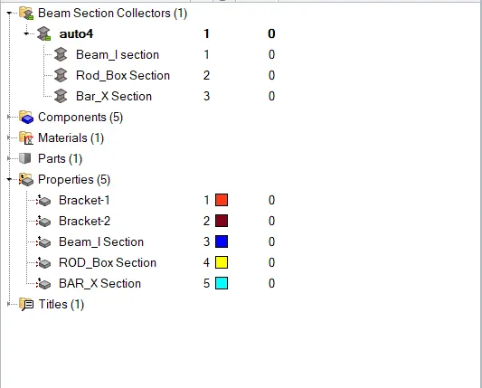
Now we can create 1D elements using ROD and BAR tools.
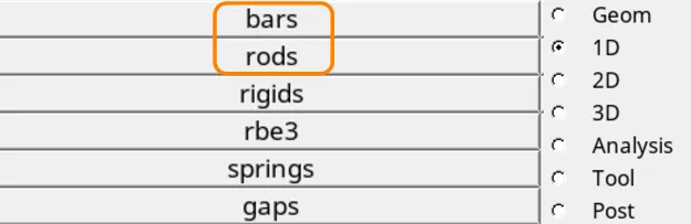
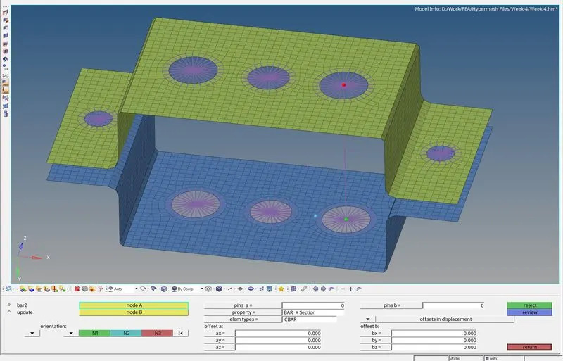
We will connect the 2 master nodes of hole C and then we will select the CBAR element type and the property we have created above.
Similarly, we can create BEAM and BAR elements.
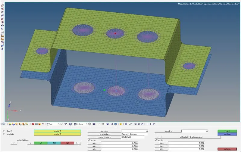
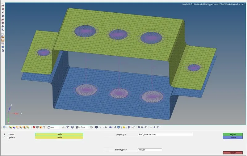
Now to apply mass to holes E & D we go to the MASSES tool under the 1D option.

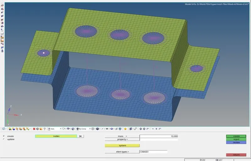
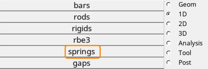
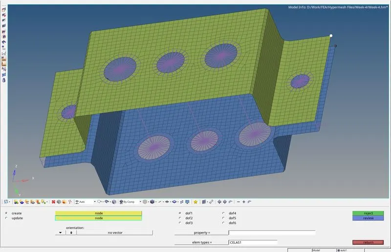
Similarly, a Spring Element can be deployed to all 4 corners using the SPRING tool.
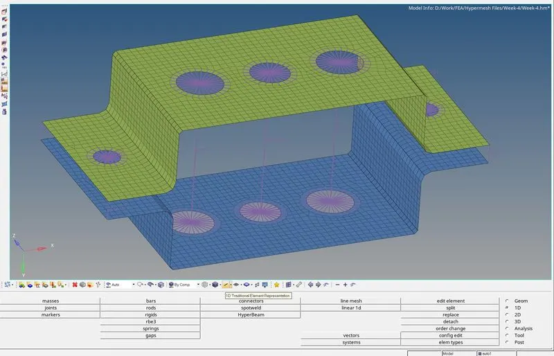
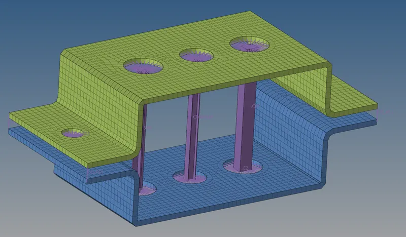
The BEAM, ROD and BAR are represented as a line now to get the proper crosssection view we will select this option.
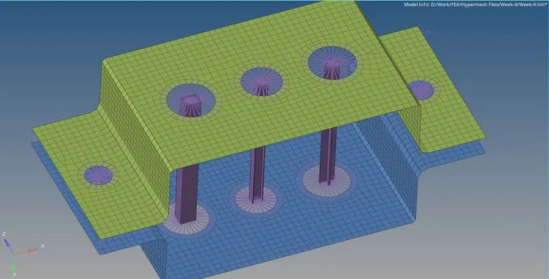
After applying thickness to 2D shell elements our final FEA model will look like this.
- LEARNING OUTCOME:
By doing this challenge I learned,
- How to Auto-mesh a surface in HyperWorks.
- How to create and deploy RBE2 and RBE3 elements in HyperWorks.
- How to create BAR, BEAM and ROD elements with appropriate cross-section.
- How to use the MASSES and SPRING tools in HyperWorks.
- How to create Property and Material CARD.
- CONCLUSION:
This concludes the 1D connection challenge by using HyperWorks.