Week 6 - Creating connection for Rear door
Aim :- the given Rear door FE model, Create and Apply different PIDs for different components. By using the same technique and the elements as shown in the video, Perform suitable connections. (No thickness need to be assigned to FE as intention is just to deploy connections).
Procedure :-
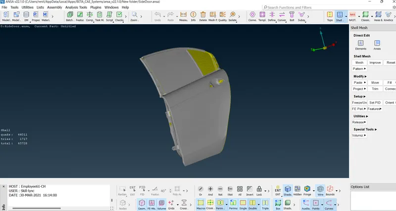
Step 1 :- import the model .
file -open -select the model - open.
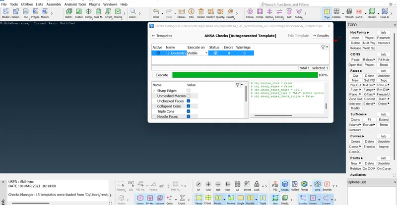
Step 2:- checking the geometry.
Check - geometry - execute .
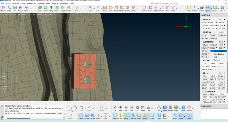
Step 3 :- creating RBE2 link with many nodes .
NASTRAN Decks - elements - RBE2 - with many nodes .
Select the nodes - loop -select the loop - ok
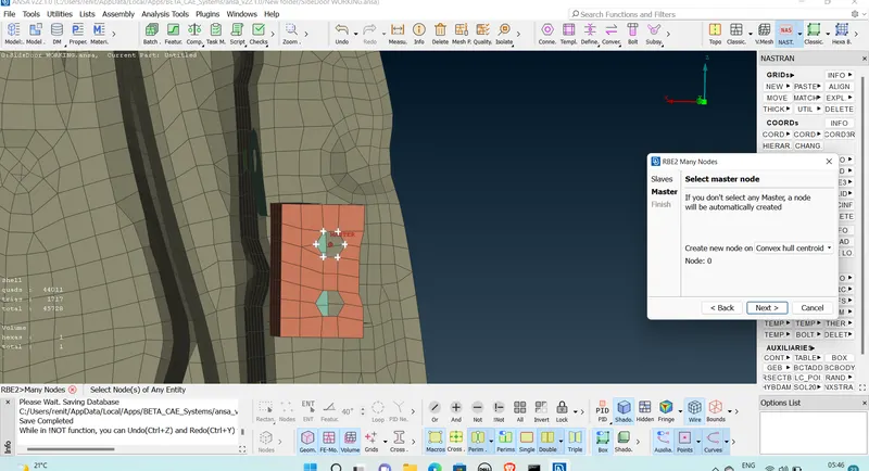
Next - create a part - ok.
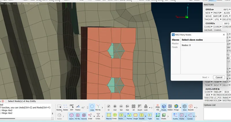
Step 4 :- Creating RBE2 link with two nodes
NASTRAN Decks - elements - RBE2 - with two nodes .
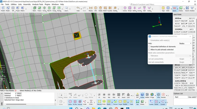
select two nodes - give name - ok.
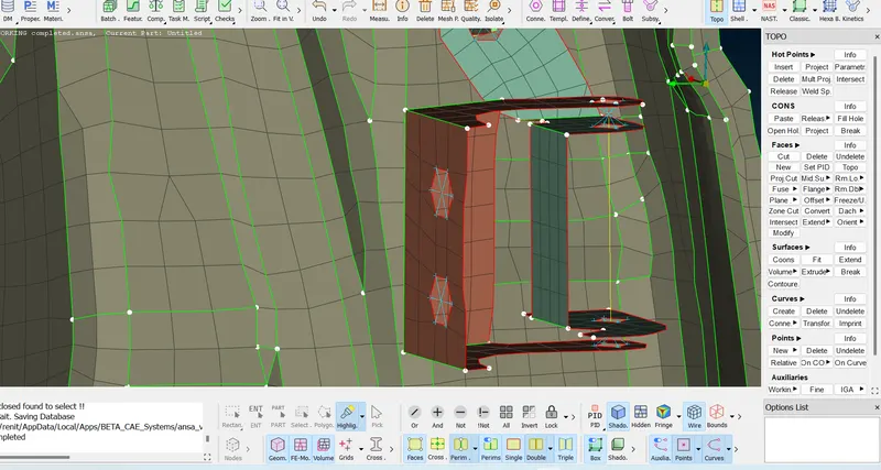
Step 5 :- Creating RBE2 link which have a movement in Z direction.
Already created 2 RBE2 link in bolt and nut .
creating the bolt stem with RBE2 with two nodes .
Assig ing the name - while giving DOF , We need to gove only 12345 .
need to remove Z rotation from rigid.
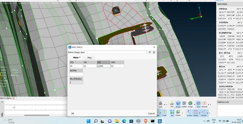
Step 6 :- Creating an automatic bolt rigid link.
Creating a 3d point on the surface.
TOPO -Point -on COG - poiunts -select the loop -create.
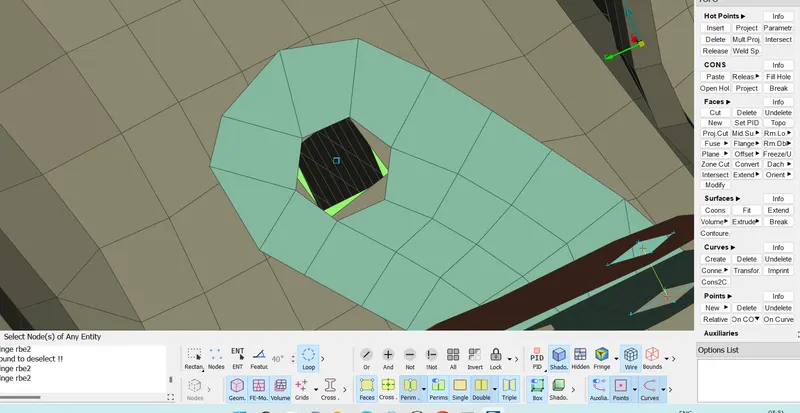
Convert the 3D points into bolts.
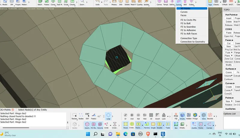
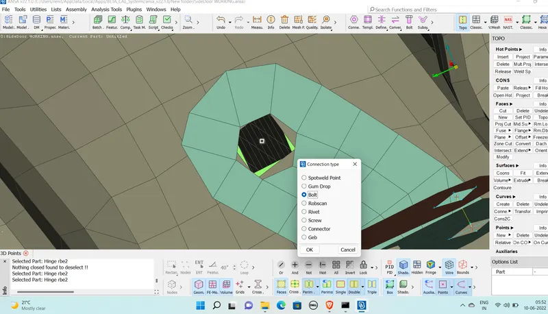
Select connection manager - select the bolt - o k.
Assign a property P1,P2,P3 number by selecting the propertys one by one
FE type - Bolt - give search distance as 10 .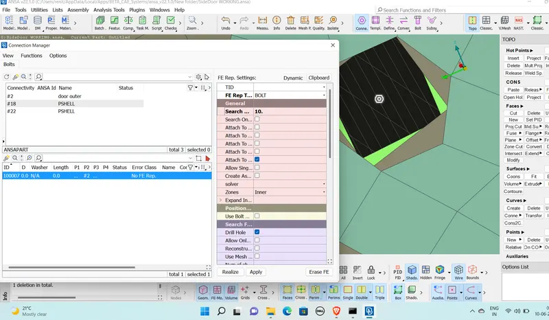
Turn on body (bolt stem) -rbe2 - Apply - realize.
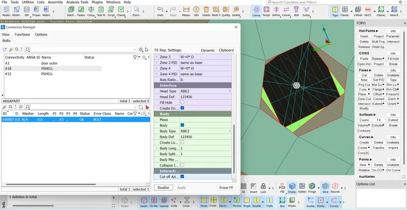
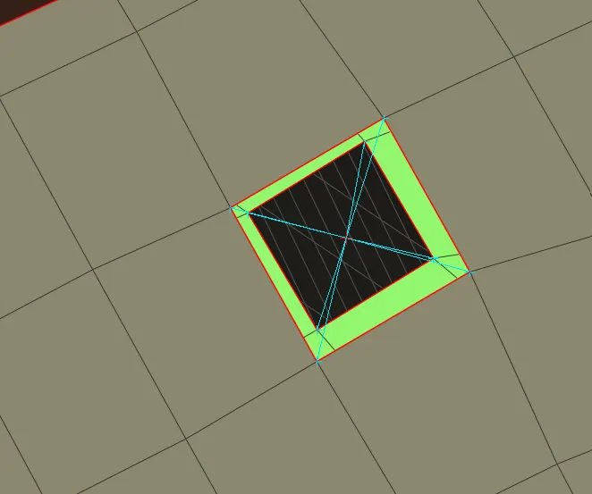
Step 7 :- Creating a RBE2 Cluster.
NASTRAN - Elements - RBE2 -wilt many nodes - select the loop of two surface - next -master node will apper between the slave nop - create.
Step 8:- Creating RBE2 link and giving mass to the handle Door.
Creating RBE2 link of both end of the Handle .
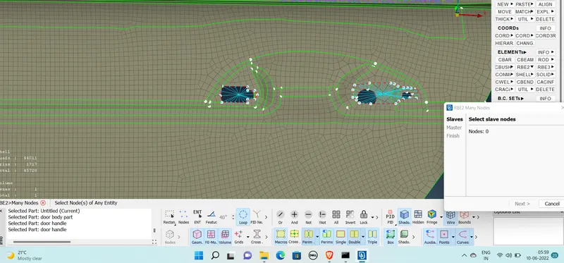
Connecting the boith RBE2 link by creating RBE2 link eith msny nodes ,a master node witll crate on the center of the RBE2 link.
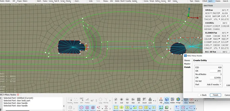
Assigning a mass
Deck -elements -CONMi - CONM2 -Nodes -Select the center node /master nodes -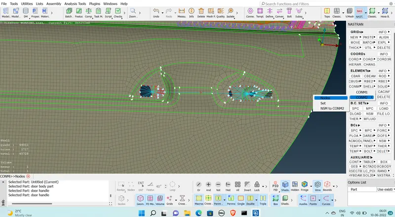
Giving a mass as 1e-10 tons - create
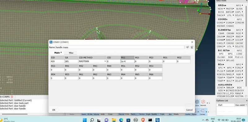
Mass created on the handle.
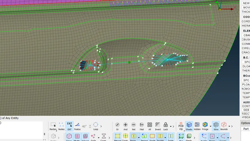
Step 9 :- Creating RBE3 bush on glass side .
Create a curve aeound the glass by selecting
Topo - Curves - curve2curve -select the end of the cons.
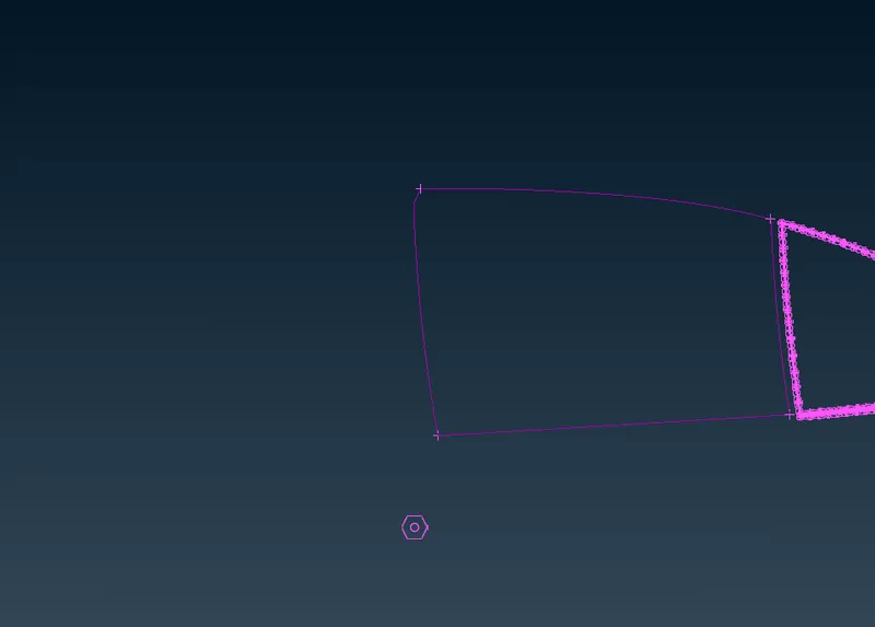
Copy the base curve using tranform - copy - select the curve - give the directio and magnitude - finish.
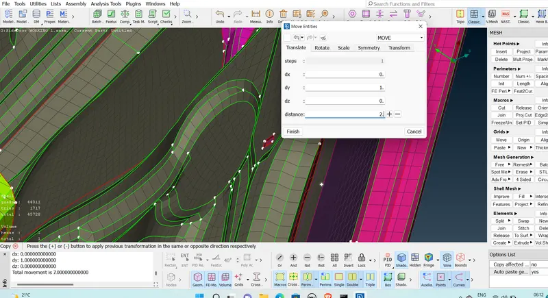
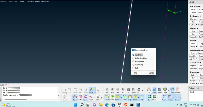
Convert the Curve into Spot line.
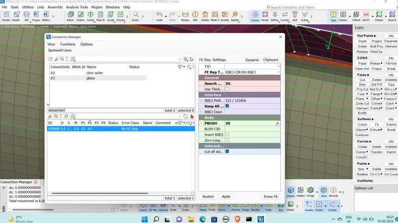
connection manager - select the spotline - assign the property P1and P2 by selecting the property .
Give FE Type as RBE3-CBUSH-RBE3 -search distance =50 - Turn on all branches - Gassign a property to CBUSH - Apply -Realize .
Created RBE3-CBUSH- RBE3.
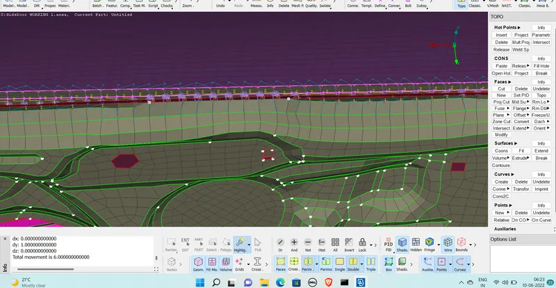
Step 10 :- Creating spotweld.
create 3d points
Topo point -on COG ,create points
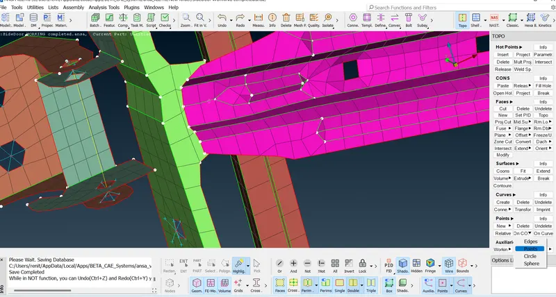
Convert 3D points into spotweld points .
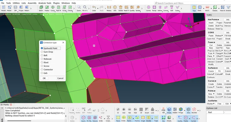
Connecting manager -select the spot weld - assign property one by one
select FE Type -RBE3 -HEXA-RBE3 - Search distance =20 ,assign solid property -create.
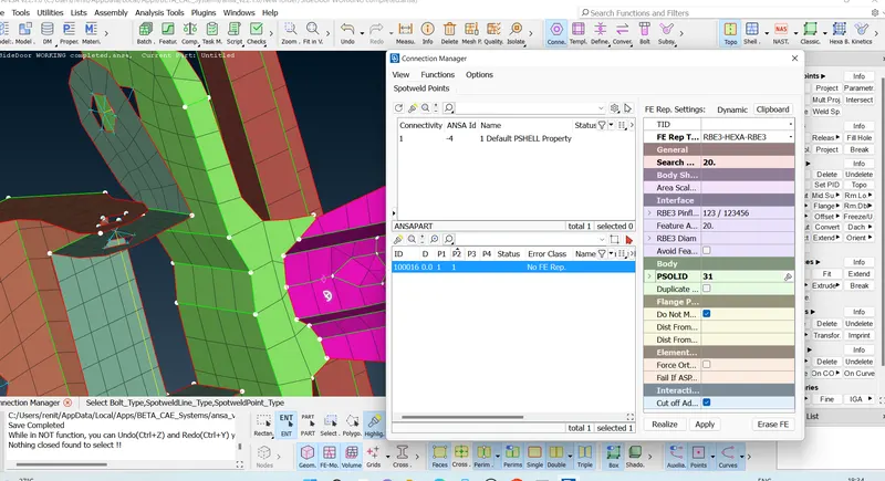
Spot weld created
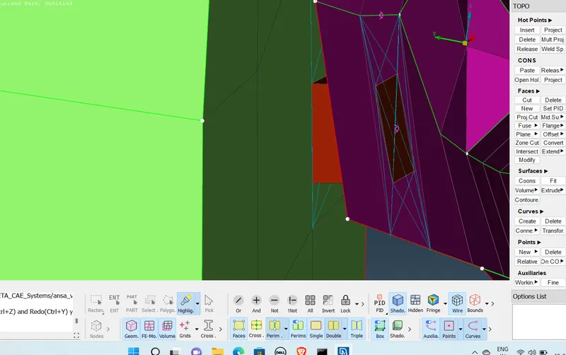
Final Model :
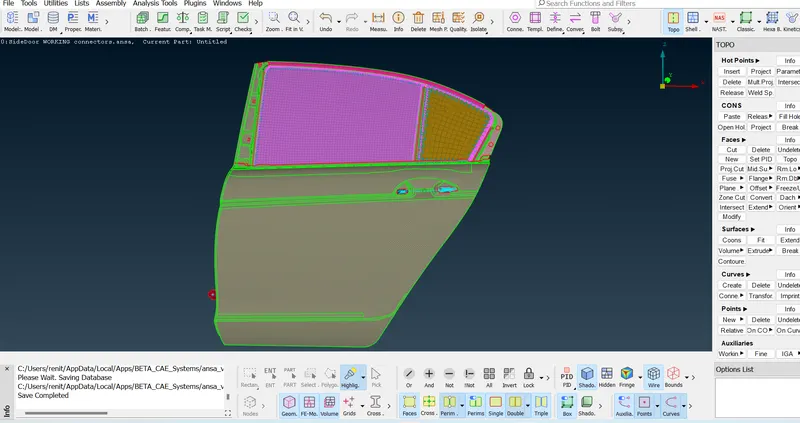
Result :- For the given Rear door FE model, Create and Apply different PIDs for different components. By using the same technique and Perform suitable connections
Learning Outcomes:-
*Learned about different connectors .
*learned about how to create 3d nodes and how to convert into connectors.
*learned about the tool uses for connectors a.
*Learned about the errors and how to realise the connectors.
Thanks
Renith Balachandran M