Week-6 Challenge: EV Drivetrain
1. Which types of power converter circuits are employed in electric and hybrid electric vehicle?
Aim:
To find the types of power converter circuits used in elctric and hybrid electric vehicle.
Types of converters:
- DC - AC Converters
- AC - DC Converters
- DC - DC Converters
- AC - AC Converters
Converters used in EV and HEVs:
In Electric and Hybrid Electric Vehicles three types of converters are used and they are listed below:
- DC - AC Converters(Inverter):
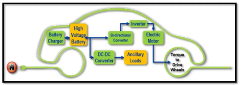
The DC - AC Converter is also known as Inverter circuit and it is widely used in the UPS Home application. The DC - AC Converter is used to convert the DC power to a suitable AC power to drive the motor drive train in the Electric and Hybrid Electric Vehicles.
- AC - DC Converters(Rectifier):
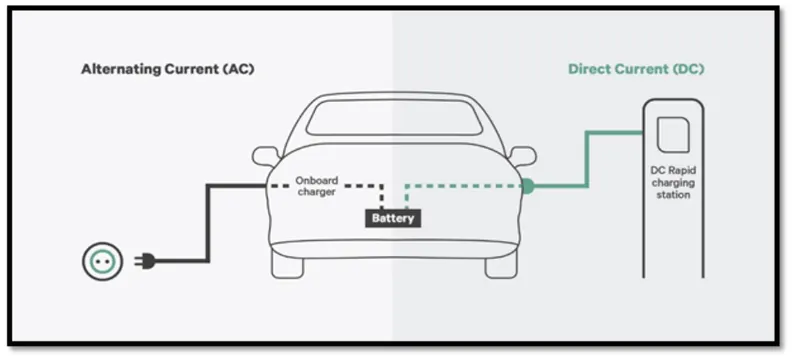
The AC - DC Converter is also known as Rectifier circuit and it is widely used in Mobile and Laptops charger application. The AC - DC Converter is used to convert the AC power to DC power which is used in On-board charger in the Electric and Hybrid Electric Vehicles. This converters will help to charge the battery packs in EVs and HEVs by converting the AC power source from charging station.
- DC - DC Converters(Chopper):
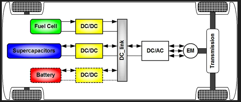
The DC - DC Converter is also known as Chopper circuit and it is widely used in Electric Trains. The DC - DC Converter is used to convert the DC power at one level to DC power at another level and it is used to deliver power for the accessories used in the Electric and Hybrid Electric vehicles.
Conclusion:
Thus the types of power converter circuits used in electric and hybrid electric vehicles are discussed.
2. An Electric Vehicle's powertrain with 72V battery pack in shown in the diagram below. The duty ratio for acceleration operation is 'd1' and for the braking operation the duty ratio is 'd2'.
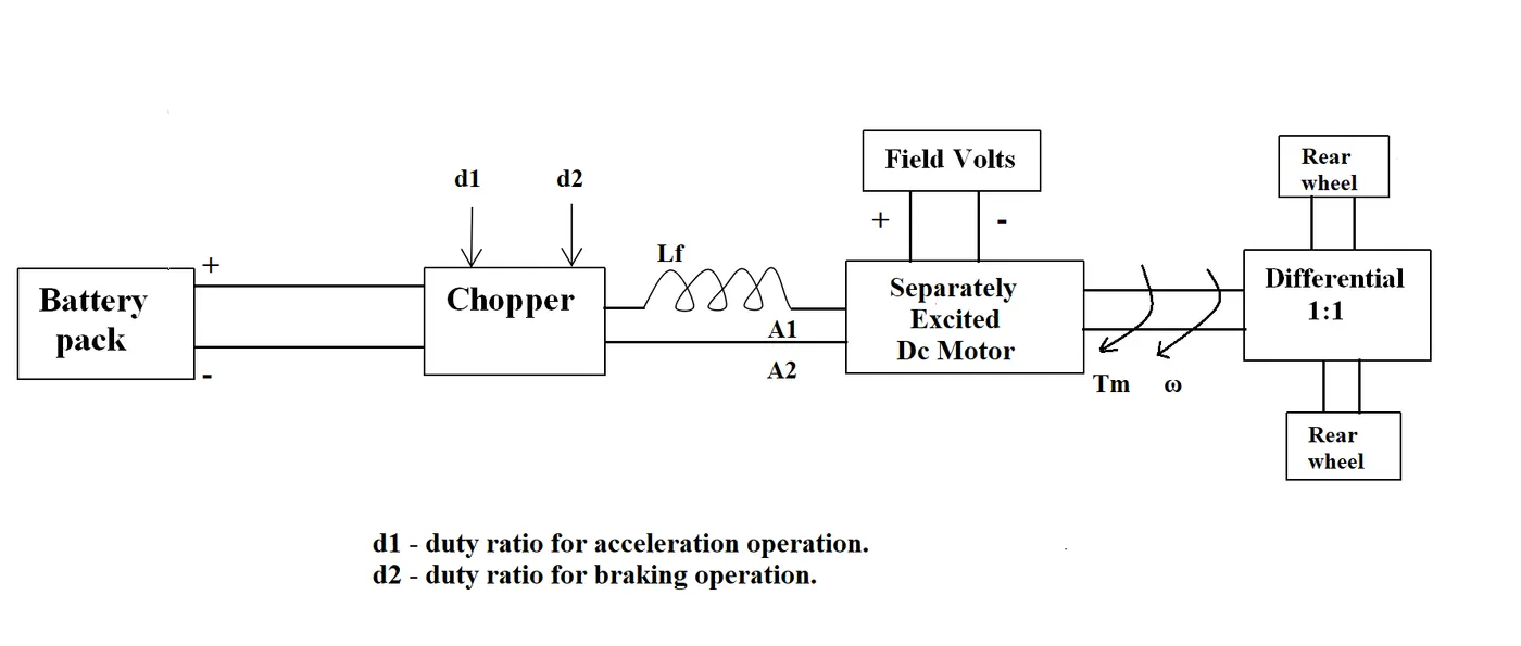
The other parameters of the electric vehicle is given below,
Motor and Controller Parameters:
Rated Armature voltage= 72 V
Rated armature current= 400 A
Ra= 0.5Ω, KΦ= 0.7 Volt second
Chopper Switching frequency= 400 Hz
The vehicle speed-torque characteristics are given by the below equation

What is EV steady state speed if duty cycle is 70%?
Aim:
To find the EV steady state speed if the duty cycle of 70% with the given data.
Given Data:
Rated voltage = 72V
Rated current = 400A
Armature resistance = 0.5Ω
KΦ= 0.7 Volt second
Tv = 24.7+(0.0051)*w2
Duty cycle = 0.7
Formula Used:
ω= V/Kϕ-Ra/Kϕ^2*T
Calculation:
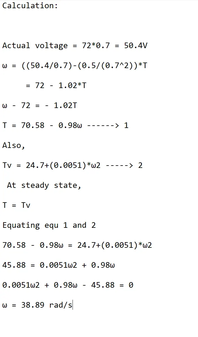
Actual voltage = 72*0.7 = 50.4V
ω = ((50.4/0.7)-(0.5/(0.7^2))*T
= 72 - 1.02*T
ω - 72 = - 1.02T
T = 70.58 - 0.98ω ------> 1
Also,
Tv = 24.7+(0.0051)*ω2 -----> 2
At steady state,
T = Tv
Equating equ 1 and 2
70.58 - 0.98ω = 24.7+(0.0051)*ω2
45.88 = 0.0051ω2 + 0.98ω
0.0051ω2 + 0.98ω - 45.88 = 0
ω = 38.89 rad/s
Conclusion:
The EV steady state speed for the duty cycle of 70% is 38.89 rad/sec.
3. Develop a mathematical model of a DC Motor for the below equation using Simulink.
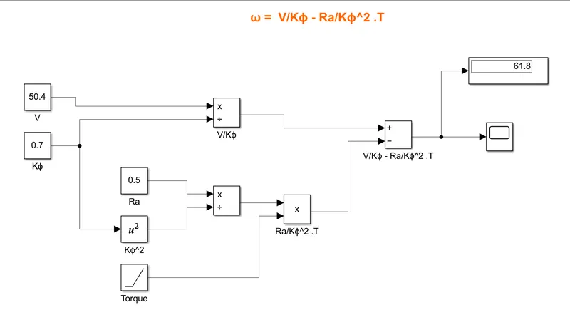
ω = V/Kϕ -Ra/Kϕ^2 . T
Aim:
To develop a mathematical model of a DC Motor for the given equation using simulink.
Blocks used in Simulink:
- Constant Block
- Product Block
- Sum Block
- Scope Block
- Square Block
- Ramp Block
Procedure:
- We need to connect the constant voltage block and motor constant block with product block to get this equation V/Kϕ.
- We need to get the constant resistance block, Ramp block as Torque, Square block for motor constant to get this equation Ra/Kϕ^2 .T.
- We need to use sum block to get the equation of V/Kϕ - Ra/Kϕ^2 .T
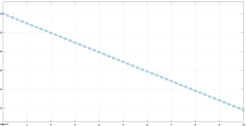
- The Scope block is connected to the output of sum block.
- The result is viewed in the scope block.
SIMULINK:
Graphical Representation:
Result:
Thus the mathematical model of a DC Motor is implemented using simulink.
4. Refer to the blog on below topic:
Induction Versus DC brushless motors by Wally Rippel, Tesla
Explain in brief about author’s perspective.
The author's perspectives are as follows:
- All engines are alike and it is up to the user's requirements. Due to improvising technology, there has been alternatives found now and then such as lead-acid batteries, DC brush motors and contact controllers has been replaced by Lithium batteries, brushless DC motors and inverters.
- There are various motors but only brushless DC and Induction motors are playing major role nowadays in EV and HEVs.
- The construction and working of the brushless DC motor and Induction motor are being discussed. The stators for the 3-phase induction motor and the DC brushless motor are virtually identical. Both the stators have "distributed windings" that are inserted within the stator core. Both drives use 3-phase modulating inverters.
- The only differences are the rotors and the inverter controls. The pros and cons of both brushless DC motors and Induction motors are being discussed by author.
- The advantages of brushless dc motors are much less rotor heat is generated. The peak point efficiency will only be a few % higher than an induction motor. The disadvantages are : as the machine size grows , the magnetic losses increase proportionately and part load efficiency drops.
- Also Permanent magnet rotors are also difficult to handle due to very large forces that comes into play when anything ferromagnetic gets close to them.
- Induction motor has some advantages : the motor has no PM magnets, the motor can start under no-load conditions. The disadvantages are : they cannot operate in DC. When operated with utility power they have limited starting torque and limited running peak torque capabilities when compared to DC brushless motor.
- The author's conclusion is that DC brushless drives will likely continue to dominate market in hybrid and plug-in hybrid electric vehicles and the Induction motor drives will likely dominate the market in pure electric vehicles.