Week -2
- Make a Simulink model of Doorbell using solenoid block:
Objective:
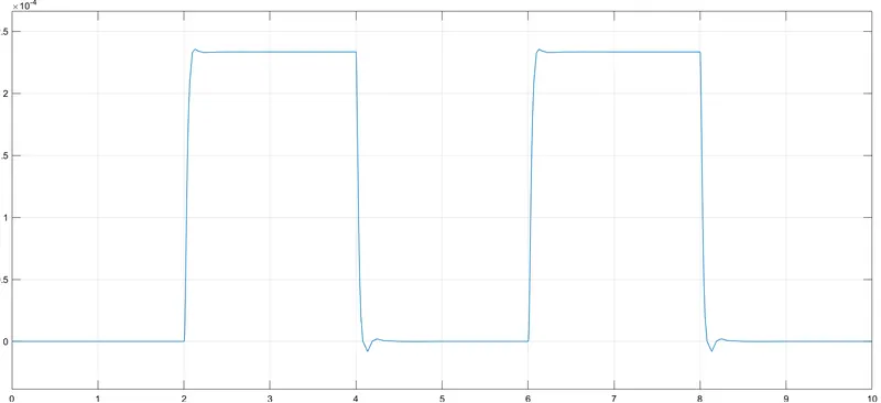
To create a simulink model of Doorbell using solenoid and to observe the physical movement of plunger when the switch is closed for 2 seconds and then released.
Requirements:
The below simulink blocks are required to implement the simulink model of Doorbell using solenoid:
- Pulse generator - This block provides the required input signal to physical port of the switch.
- Simulink - PS converter - This block is used to convert simulink signal into physical signal.
- Switch - This block is used for switching the signals to solenoid block based on the input signal to physical port.
- Battery - This block provides power supply to solenoid block.
- Electrical reference - This block will act as a ground for electrical network.
- Solenoid - This block implements electrical and mechanical characteristics of a solenoid.
- Ideal Translational Motion Sensor - This block is used to sense the plunger position/movement.
- PS - Simulink converter - This block is used to convert physical signal into simulink signal.
- Solver configuration - This block defines solver settings to use for simulation.
- Scope - This block is used to view the output/position of the plunger.
Procedure:
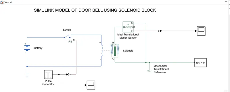
We need to use the above mentioned simulink blocks in order to create a simulink model of Doorbell using solenoid block.
- First we need to connect the pulse generator block with physical port of the switch block.
- Pulse generator will provide the simulink signal which is converted using simulink - PS converter block.
- The positive terminal of battery block is connected with the one end of the switch and other end of the switch is connected with positive terminal of solenoid.
- The negative terminal of solenoid is connected with negative terminal of battery and also electrical reference is connected to negative terminal of battery.
- The mechanical port of solenoid R is connected to motion sensor in order to detect the position of plunger.
- The mechanical port of solenoid(C) and motion sensor(C) is connected with reference block. The solver configuration block is connected with mechanical reference block.
- The output from the motion sensor is connected to scope block through PS-Simulink converter block.
- We will obtain the output with fluctuations in order to remove the fluctuations we need to increase the damping parameter in the solenoid block.
Block diagram:
Graphical Output:
Result:
Thus a simulink model of Doorbell using solenoid is created and pluger movement is observed where the switch is closed for 2seconds.
2. Use a thermistor to sense the temperature of a heater & turn on or turn off the fan as per the below conditions:
Objective:
To create a simulink block in order to sense the temperature of a heater using thermistor and turn on or turn off for certain conditions mentioned below:
Fan must be ON above the temperature of 25 °C and OFF below the temperature of 25 °C.
Requirements:
Initial conditions : 20 °C from 0 to 10 seconds, 27 °C from 10 to 30 seconds, 23 °C from 30 to 50 seconds.
The below mentioned blocks are required to acheive the required simulation:
- Signal builder - In order to achieve the above initial conditions we need to build the input signal accordingly and this block is used to obtain desired input signal.
- Controlled Temperature Source - This block is used for controlled thermal energy source to thermistor.
- Thermistor - Thermistor is a thermal dependent resistor so we use this block to turn on and off the fan.
- Voltage sensor - This block is used to sense the voltage difference generated by thermistor.
- Resistor - This block is used as a load resistance in order to sense the voltage across the thermistor.
- Switch - This block provides the desired output only when the input is greater than threshold value.
- Simulink - PS and PS - Simulink converter - These blocks are used to convert respective signals of one state to another state.
- Controlled Voltage Source - This block is used to provide voltage source to DC motor.
- DC motor - This block is used as fan in this simulation.
- Scope - This block is generally used to view the results/graphical output.
- Solver Configuration - This block defines solver settings to use for simulation.
- Reference - This block is used as a reference for respective blocks.
Procedure:
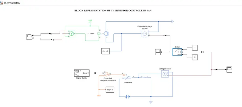
- First we need to connect the signal builder block to the controlled temperature source which will maintain the temperature difference regardless of heat flow.
- The thermal input to the termistor is provided through controlled temperature source and battery is used to provide the supply to termistor.
- The resistor is connected in series with the termistor and voltage sensor is connected across the resistor in order to sense the voltage difference across thermistor terminals.
- The output of voltage sensor is provided to switch and the switch will provide the output when the output from voltage sensor is grater than threshold value.
- The threshold value is set to 0.012 which is a equivalent voltage value when the temperature is 25 °C.
- The output of the switch is provided to voltage source which in turn is connected to DC motor.
- The DC motor is connected to motion sensor and the output of motion sensor is provided to scope.
- The converter blocks are used to convert physical signal to simulink and viceversa.
Block diagram:
Graphical Output:
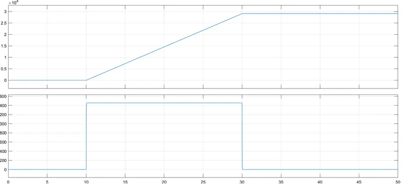
Figure 1 : The above graph represents the angular velocity and angle of the fan.
Result:
Thus the fan is turned on when the temperature is above 25 °C and turned off below 25 °C.