Week - 4
- Implement control logic of a “washing machine” using Stateflow as per given sequence:
- If the power supply is available, the system gets activated
- If the Water supply is not available, stop the process & indicate through LED
- Soaking time should be 200s followed by Washing time of 100s.
- Then rinsing happens for next 20s & dryer runs for 50s
Objective:
To implement the control logic of a "Washing machine" using stateflow method.
Requirement:
The below blocks and stateflow chart is necessary to implement the washing machine control logic:
- Constant Block - This block is used as a input power supply and water supply for the control logic of washing machine.
- Display Block - This block is used to display the different stages of control logic of washing machine.
- Lamp Block - This block is used as a indication for different stages of washing machine.
- Chart - The control logic are implemented using this chart from stateflow. Chart consists of state, default transition, junction etc
Procedure:
- First we need to use chart from the stateflow to implement the control logic of washing machine inside the chart block.
- In chart block we need to use state with default transition as first state because the control logic will be implemented from the default transition.
- First state is Activation state where it transmits power supply to next state.
- The next state is Watercheck in which it is divided into two different states like Soak and Stop.
- If the water supply is not available then it enters into Stop state.
- If water supply is availble then it enters into Soak state and after 200seconds of soaking time the control logic enters into washing state.
- After washing has been implemented for 100sec it enters into Rinsing state.
- Rinsing will be implemented for 20sec and it enters into Drying state.
- After drying is implemented for 50sec and it enters into final state of Finish.
- Here the states like power, soak, washing, rinsing, drying, stop and finish are connected with lamp for indication of different states.
- Here power supply, water supply are the input ports and the output ports are connected with display.
Block diagram:
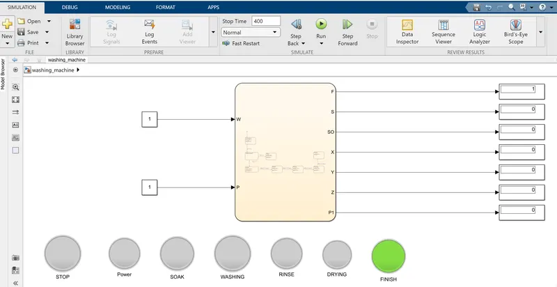
Figure 1 : The above drawing shows the implementation of washing machine control logic.
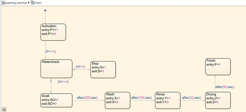
Figure 2 : The above drawing shows the different states of control logic for washing machine.
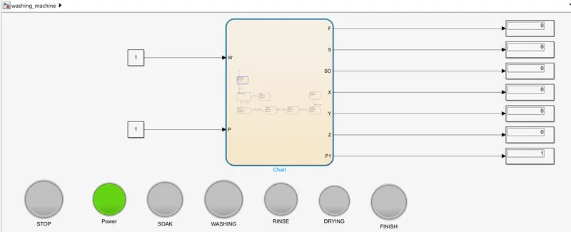
Figure 3 : The above drawing shows the power supply state of control logic for washing machine.
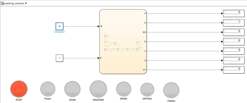
Figure 4 : The above drawing shows the Stop state of control logic for washing machine when water supply is not available.
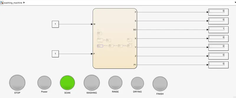
Figure 5 : The above drawing shows the Soak state of control logic for washing machine.
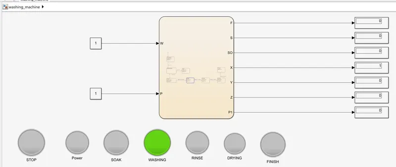
Figure 6 : The above drawing shows the Washing state of control logic for washing machine.
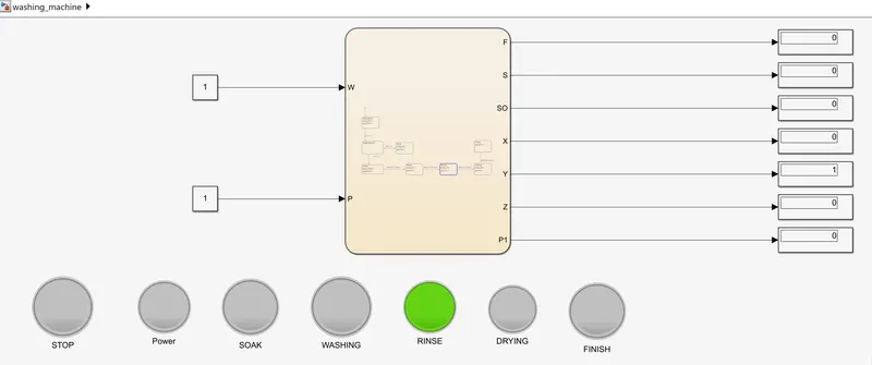
Figure 7 : The above drawing shows the Rinsing state of control logic for washing machine.
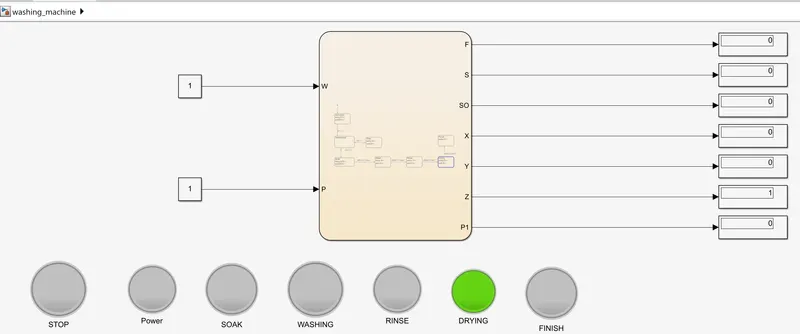
Figure 8 : The above drawing shows Drying state of control logic for washing machine.
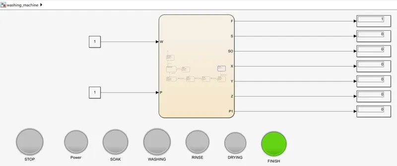
Figure 9 : The above drawing shows Finish state of control logic for washing machine.
Result:
Thus the control logic of "Washing machine" is implemented using stateflow.
2. Make a Simulink chart for the “Gear shift” logic as per below conditions:
Speed Range(kmph) Gear
0 to 15 1
16 to 25 2
26 to 40 3
41 to 60 4
Above 61 5
Give speed input while the simulation is running & display the gear number.
Objective:
To implement a simulink chart for the "Gear shift" logic for different speed range and display the gear number.
Requirement:
- Constant block - This block provides the input to the slider gain.
- Slider Gain block - This block is used to provide speed input while running the simulation.
- Display block - This block is used to show the gear number.
- Chart - This block is used to implement the gear shift logic using stateflow
Procedure:
- We use slider gain block and it is used as a speed input to gear.
- The output of the slider gain is connected to input port of the chart.
- In chart we will implement the state logic for gear shift.
- The first state is Gear_1 and this state provides the output to display as gear 1.
- The next state Gear_2 will be moved when the condition of speed X greater than 15kmph.
- When the condition of speed X greater than 25kmph then Gear_2 state is moved to Gear_3 state.
- When the condition of speed X greater than 40kmph then Gear_3 state is moved to Gear_4 state.
- When the condition of speed X greater than 61kmph then Gear_4 state is moved to Gear_5 state.
- The reverse state transition will occur in the similar conditions viceversa.
- The output gear number will be displayed in the display block based on the speed input.
Block diagram:
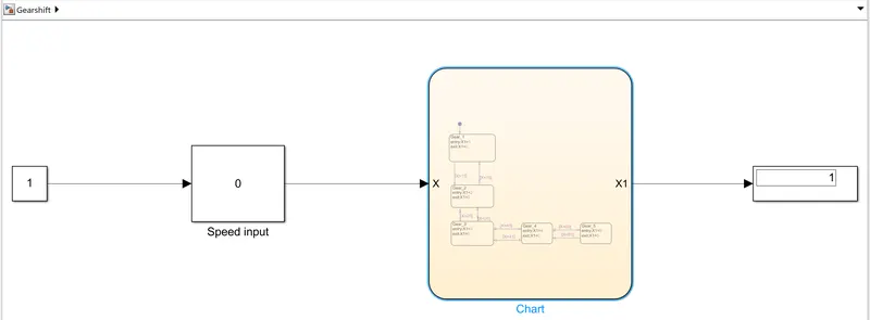
Figure 1 : The above model shows the Gear shift logic
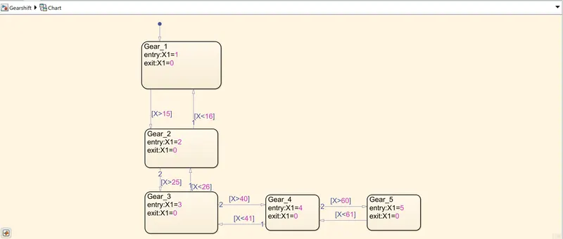
Figure 2 : The above drawing shows the different states of the gear shift using stateflow.
Result:
Thus the gear shift logic is implemented using stateflow