Week-6 Challenge: EV Drivetrain
OBJECTIVE 1: Which types of power converter circuits are employed in electric and hybrid electric vehicle?
ANS: TYPES OF POWER CONVERTERS IN HEV& PURE EV
- AC-DC CONVERTER RECTIFIER.
- DC-DC CONVERTER CHOPPER.
- DC-AC CONVERTER INVERTER.
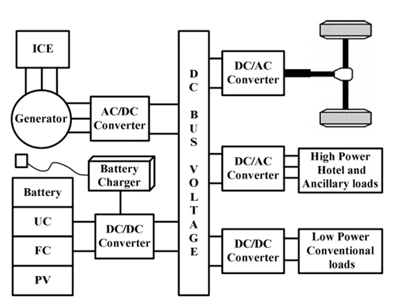
AC-DC CONVERTER RECTIFIER
AC-DC conversion is widely used in several applications such as changing speed drivers, switch mode power supplies, uninterrupted power supplies and battery energy storage..
AC-DC converters, popularly noted to as rectifier, are introduced to using diodes and thyristor to give uncontrolled and controlled dc power with unidirectional and bidirectional power flow..
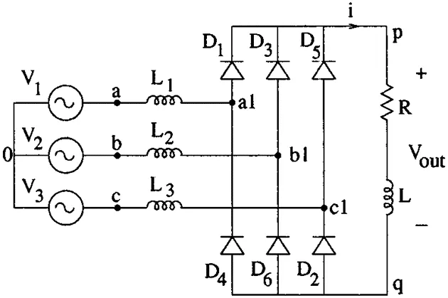
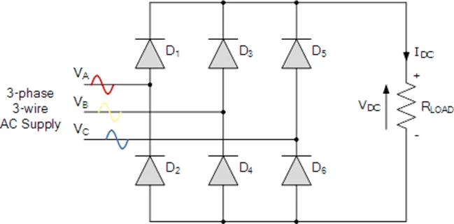
The top group diodes (D1, D3, D5) form a “Maximum value circuit” and therefore the maximum of the phase voltages van, vbn, vcn appears at the positive dc bus..
Operation of the converter can be explained as follows:
- On the other hand, the bottom group diodes (D2, D4, D6) form a “Minimum value circuit”. Therefore, the minimum of the phase voltages van, vbn and vcn appears at the negative dc bus..
- Therefore, the output voltage waveform at any instant is equal to the maximum of the six-line voltages vab, vbc, vca, vba, vcb and vac provided at least one diode from the top group and one from the bottom group conducts at that instant..
- None of the diodes will conducts, however if the output capacitor voltage is larger than the maximum line voltage..
- All the six operating modes of a 3-phase bridge rectifier namely, D1D2, D2D3, D3D4, D4D5, D5D6 and D6D1 appear in that order.
- In addition, an additional operating mode in which none of the diodes conduct appears in the conduction diagram as shown in Fig. 12.3 (b).
- During these periods the output capacitor discharges through the load.
- As the capacitor voltage decreases its voltage becomes equal to the incoming line voltage.
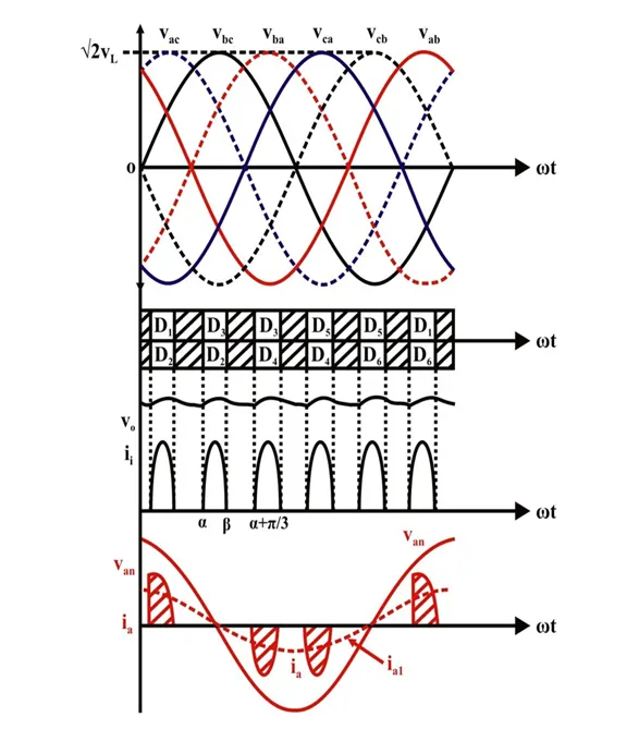
At this instant the appropriate diodes from both the top and the bottom group starts conducting and continuous to do so till the sum of the capacitor charging current and the load current becomes zero.
DC-DC CONVERTER CHOPPER
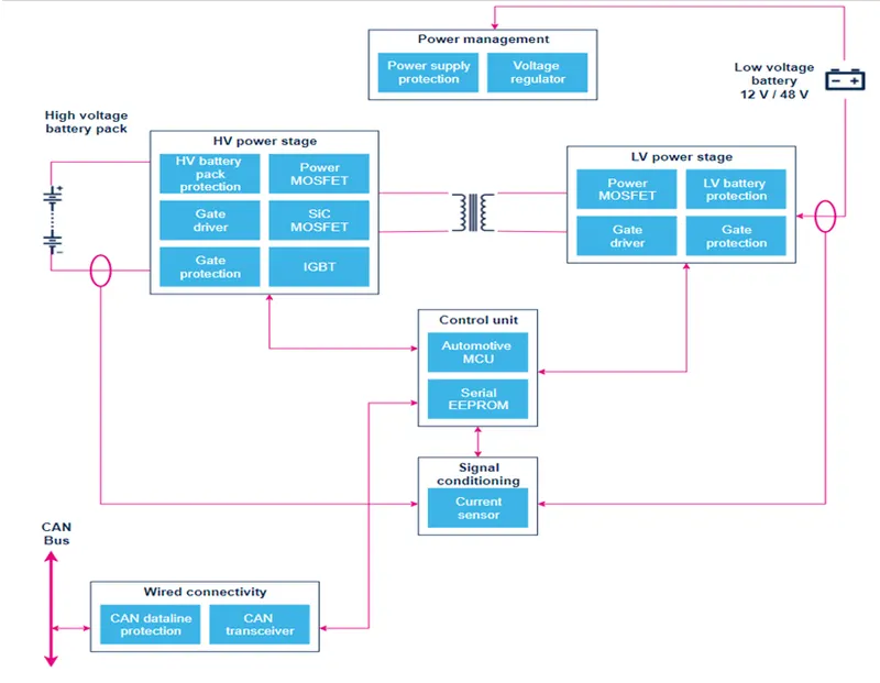
- In electric engineering, a DC-to-DC converter is a category of power converters and it is an electric circuit which converts a source of direct current (DC) from one voltage level to another, by storing the input energy temporarily and then releasing that energy to the output at a different voltage.
- The storage may be in either magnetic field storage components (inductors, transformers) or electric field storage components (capacitors).
- DC/DC converters can be designed to transfer power in only one direction, from the input to the output.
- However, almost all DC/DC converter topologies can be made bi-directional. A bi-directional converter can move power in either direction, which is useful in applications requiring regenerative braking.
- The amount of power flow between the input and the output can be controlled by adjusting the duty cycle (ratio of on/off time of the switch).
- Usually, this is done to control the output voltage, the input current, the output current, or to maintain a constant power.
- Transformer-based converters may provide isolation between the input and the output.
- The main drawbacks of switching converters include complexity, electronic noise and high cost for some topologies.
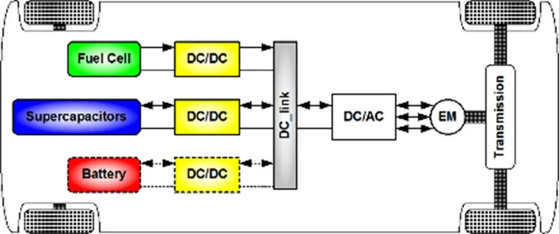
DC-AC CONVERTER INVERTER:
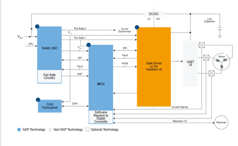
- An inverter is a device that converts DC power to the AC power used in an electric vehicle motor.
- The inverter can change the speed at which the motor rotates by adjusting the frequency of the alternating current.
- It can also increase or decrease the power or torque of the motor by adjusting the amplitude of the signal.
- EV traction inverters must provide high power – in the range of 80 to 200+ kW- to the traction motor, withstand high temperatures and be as small and as light as possible.
- Key performance parameters for inverters are high efficiency - for longer battery life, high-power density - for small size and low weight, and high levels of functional safety to protect the vehicle operator and systems.
- The inverter converts energy from the high-voltage battery to multiphase AC current to drive the traction motor, which is a 3-phase inductive load.
Electronics in the inverter control this power conversion to the traction motor with highest possible efficiency and reliability and therefore:
- Precisely control, monitor and protect the high-power switches to achieve energy and high reliability
- Accurately and efficiently control the motor speed and torque
- Enable the highest level of functional safety in compliance with ISO 26262 requirements
OBJECTIVE 2: An Electric Vehicle's powertrain with 72V battery pack in shown in the diagram below. The duty ratio for acceleration operation is 'd1' and for the braking operation the duty ratio is 'd2'.
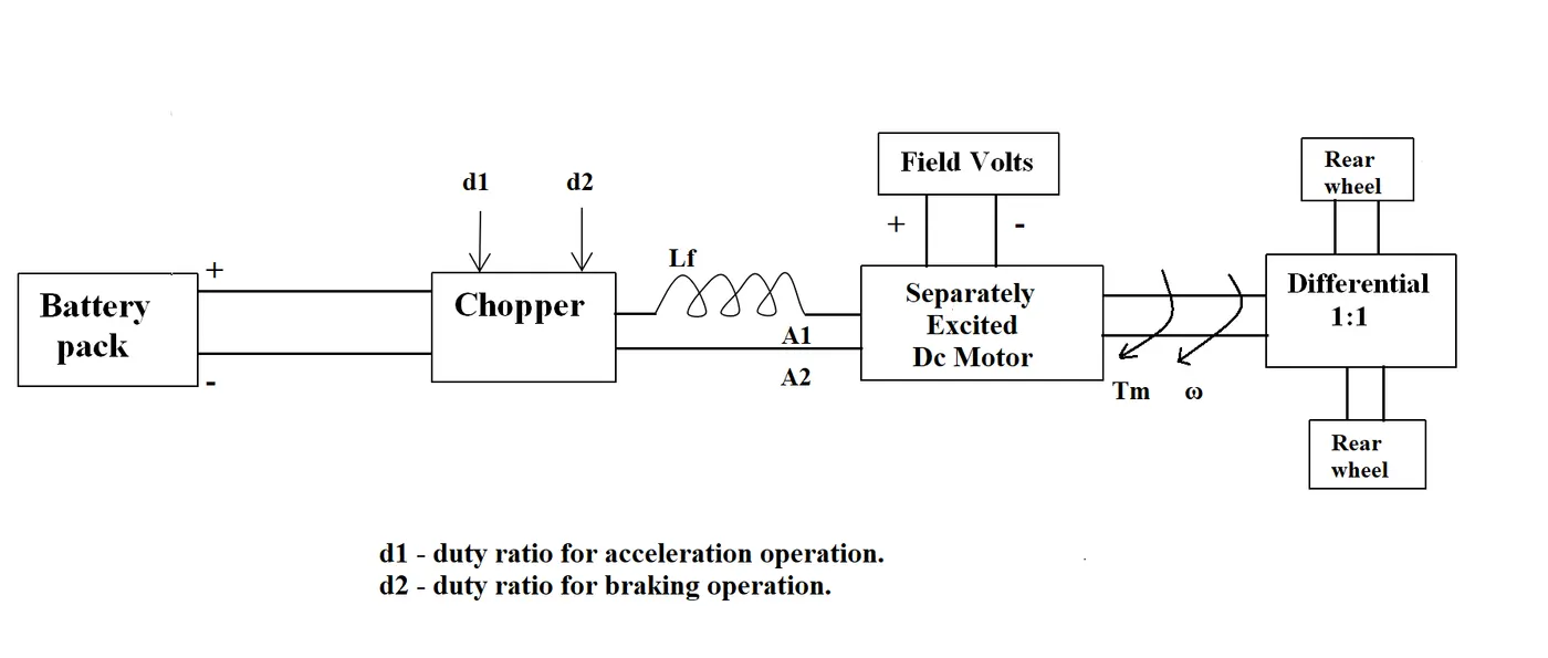
The other parameters of the electric vehicle is given below,
Motor and Controller Parameters:
Rated Armature voltage= 72 V
Rated armature current= 400 A
Ra= 0.5Ω, KΦ= 0.7 Volt second
Chopper Switching frequency= 400 Hz
The vehicle speed-torque characteristics are given by the below equation

What is EV steady state speed if duty cycle is 70%?
ANS: Switching frequency = 400hz
Tv = 24.7 + (0.0051)w2
Duty cycle = 70%
Output voltage from chopper = 72*(70/100)
V0 = 50.4
Ra = 0.5
Kø = 0.7
Putting all the values of given parameters,
Torque vs Speed Relation,
Tv = [V0 * (Kø) / Ra ] – [w(Kø)2 / Ra ]
Tv = [50.4 * (0.7) / 0.5 ] – [w(0.7)2 / 0.5 ]
Tv = [70.56] – [0.98w]…………………(2)
Equating both the equation, from (1) & (2),
Tv = [70.56] – [0.98w] = [ 24.7 + (0.0051)w2]
0.0051w2 + 0.98w – 45.89 = 0
Solving quadratic equation,
x = -b ± ( b2 – 4ac ) ½
w = -0.98 ± ( 0.982 – 4(0.0051)(-45.89) ½
w = -0.98 ± (1.377)
w = 38.92 rad/sec.
accepting the positive speed result.
OBJECTIVE 3: Develop a mathematical model of a DC Motor for the below equation using Simulink.
ωω= V/Kϕϕ -Ra/Kϕϕ^2 .T
ANS: As given in statement
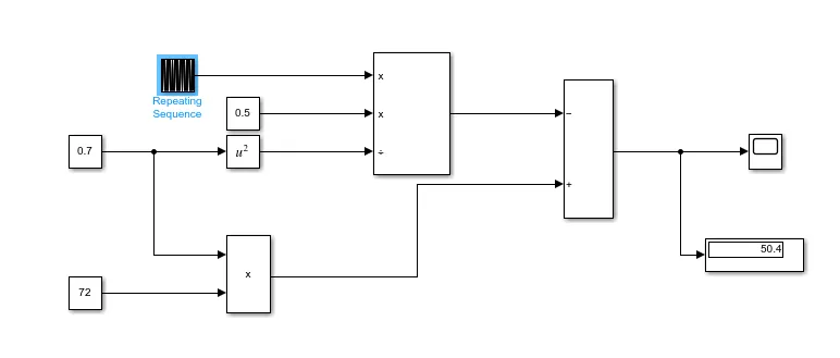
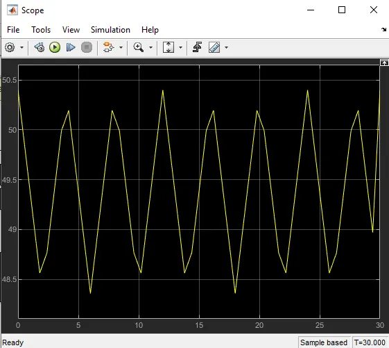
Simulink model is modelled for the given equation of dc motor.
Used Simulink block:
- Constant
- Scope
- Repeating sequence
- Display
- Multiply / division
- Add/subtract
SIMULINK MODEL:
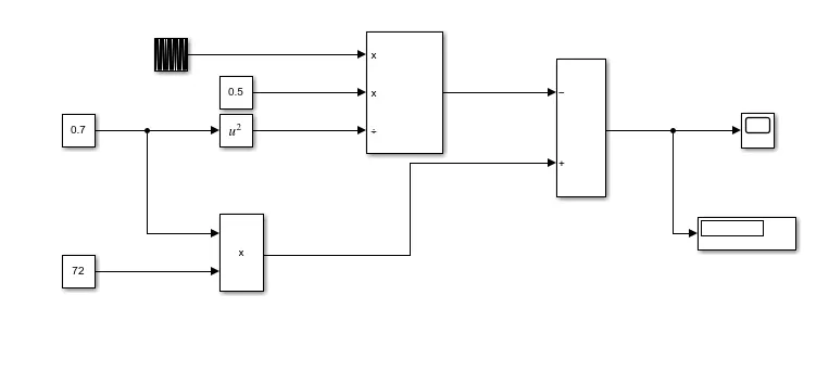
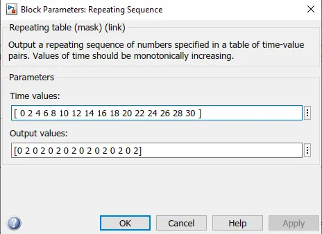
RESULT:
PLOT:
OBJECTIVE 4 : Induction Versus DC brushless motors by Wally Rippel, Tesla Explain in brief about
ANS: Brushless DC Motor: -
The rotor includes two or more permanent magnets that generate a DC magnetic field. In turn, this magnetic field enters the stator core (a core made up of thin, stacked laminations) and interacts with currents flowing within the windings to produce a torque interaction between the rotor and stator. As the rotor rotates, it is necessary that the magnitude and polarity of the stator currents be continuously varied – and in just the right way - such that the torque remains constant and the conversion of electrical to mechanical energy is optimally efficient. The device that provides this current control is called an inverter. Without it, brushless motors are useless motors.
- Permanent magnets are expensive
- Permanent magnets are difficult to handle due to its very large force of attraction with ferromagnetic get in close to it
Induction motor:
A forerunner of the 3-phase induction motor was invented by Nikola Tesla before 1889.The stators for the 3-phase induction motor and the DC brushless motor are virtually identical. Both have three sets of “distributed windings” that are inserted within the stator core. The essential difference between the two machines is with the rotor. Unlike DC brushless rotor, the induction rotor has no magnets – just stacked steel laminations with buried peripheral conductors that form a “shorted structure.” Currents flowing in the stator windings produce a rotating magnetic field that enters the rotor. In turn, the frequency of this magnetic field as “seen” by the rotor is equal to the difference between the applied electrical frequency and the rotational “frequency” of the rotor itself. Accordingly, an induced voltage exists across the shorted structure that is proportionate to this speed difference between the rotor and electrical frequency. In response to this voltage, currents are produced within the rotor conductors that are approximately proportionate to the voltage, hence the speed difference. Finally, these currents interact with the original magnetic field to produce forces – a component of which is the desired rotor torque. When a 3-phase induction motor is connected to utility type 3-phase power, torque is produced at the outset; the motor has the ability to start under load. No inverter is needed. The fact that induction motors are directly compatible with conventional utility power is the main reason for their success. In contrast, a brushless DC motor produces no starting torque when directly connected to fixed frequency utility power. They really need the aid of an inverter whose “phase” is maintained in step with the angular position of the rotor.
Limitations of 3 Phase induction motor
- Cannot operate from DC
- AC is mandatory to operate,
- Shaft speed is proportional to the line frequency
- Inverter is required to power an induction machine from battery or other dc source.
- To adjust speed inverter frequency, have to adjust
- Low torque performance while comparing with DC machines
- Feedback loops to be added and the inverter produces exact frequency that required for motor those induction motor is compatible with DC and DC brushless for vehicle application.
Both DC brushless and induction drives use motors having similar stators. Both drives use 3-phase modulating inverters. The only differences are the rotors and the inverter controls. And with digital controllers, the only control differences are with control code. (DC brushless drives require an absolute position sensor, while induction drives require only a speed sensor; these differences are relatively small.)
One of the main differences is that much less rotor heat is generated with the DC brushless drive. Rotor cooling is easier and peak point efficiency is generally higher for this drive. The DC brushless drive can also operate at unity power factor, whereas the best power factor for the induction drive is about 85 percent. This means that the peak point energy efficiency for a DC brushless drive will typically be a few percentage points higher than for an induction drive. In an ideal brushless drive, the strength of the magnetic field produced by the permanent magnets would be adjustable. When maximum torque is required, especially at low speeds, the magnetic field strength (B) should be maximum – so that inverter and motor currents are maintained at their lowest possible values. This minimizes the I² R (current² resistance) losses and thereby optimizes efficiency. Likewise, when torque levels are low, the B(magnetic field strength) field should be reduced such that eddy and hysteresis losses due to B(magnetic field strength )are also reduced. Ideally, B should be adjusted such that the sum of the eddy, hysteresis, and I² losses is minimized. Unfortunately, there is no easy way of changing B with permanent magnets. induction machines have no magnets and B fields are “adjustable,” since B is proportionate to V/f (voltage to frequency). This means that at light loads the inverter can reduce voltage such that magnetic losses are reduced and efficiency is maximized. Thus, the induction machine when operated with a smart inverter has an advantage over a DC brushless machine – magnetic and conduction losses can be traded such that efficiency is optimized. This advantage becomes increasingly important as performance is increased. With DC brushless, as machine size grows, the magnetic losses increase proportionately and part load efficiency drops. With induction, as machine size grows, losses do not necessarily grow. Thus, induction drives may be the favored approach where high-performance is desired; peak efficiency will be a little less than with DC brushless, but average efficiency may actually be better.