Week-6 Challenge: EV Drivetrain
1. The main purpose of Power converter is to control and process the flow of electrical energy based on the load connected to it. So the voltage and current can be controlled and delivered to loads.
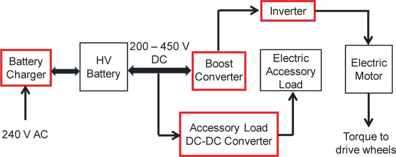
Each power Electronic system conisist of 4 segments they are, input supply, power electronic circuit,output to load, control unit.
The main power electronic part has TRIAC or IGBT or SCR as the main power electronics element.Also consist of transformer, choke, capacitor, fuse, resistor , inductor etc. The control unit consist of signal from input of driver, so it is in the form of analog or digital signal.
- AC-DC (rectifier)
- DC-AC (inverter)
- DC-DC (chopper)
- AC-AC (cyclo converter)
Rectifier:
A rectifier is an electronic device that converts an alternating current into a direct current by using one or more P-N junction diodes. A diode behaves as a one-way valve that allows current to flow in a single direction. This process is known as rectification.A rectifier can take the shape of several physical forms such as solid-state diodes, vacuum tube diodes, mercury-arc valves, silicon-controlled rectifiers, and various other silicon-based semiconductors switches.
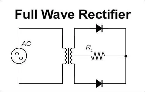
Inverter:
The basic role of an inverter is to change DC power into AC power. The AC power can be supplied to homes, and industries using the public utility otherwise power grid, the alternating-power systems of the batteries can store only DC power.
Chopper:
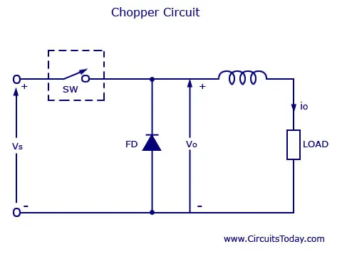
A chopper is a device that converts fixed DC input to a variable DC output voltage directly. Essentially, a chopper is an electronic switch that is used to interrupt one signal under the control of another.
For all the chopper configurations operating from a fixed DC input voltage, the average value of the output voltage is controlled by periodic opening and closing of the switches used in the chopper circuit. The average output voltage can be controlled by different techniques namely:
- Pulse width Modulation
- Frequency modulation
- Variable frequency, variable pulse width
- CLC control
Cycloconverter:
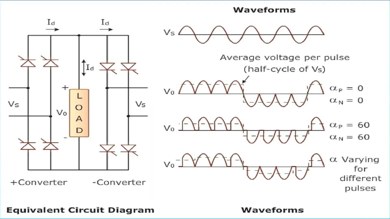
A cycloconverter (also known as a cycloinverter or CCV) converts a constant voltage, constant frequency AC waveform to another AC waveform of a different frequency. A cycloconverter achieves this through synthesizing the output waveform from segments of the AC supply (without an intermediate DC link).
2. One of the torque eqn is given in the question:
T= 24.7 + (0.0051)ω^2
Duty Cycle=70%=0.7
Voltage = 72v
Terminal voltage = 72*0.7 = 50.4v
ω = (Vt/Kϕ)- ((Ra/(Kϕ)^2)) * T
As the eqn given in the question is w.r. to torque. we should rearrange the eqn.
T = (((Vt*(Kϕ))/Ra) - ((ω*((Kϕ)^2))/Ra)
T= ((50.4*0.7)/0.5)-((ω*(0.7^2))/0.5)
T = 70.56 - (0.98ω)
Using the above eqn and the eqn from the question
24.7 + (0.0051)ω^2 = 70.56 - (0.98ω)
(0.0051)ω^2 + (0.98ω) - 45.86 = 0
divide the above eqn with 0.0051 so that wa can apply formula to find the roots of quadratic eqn:
ω^2 + 192.1568ω - 8992.1568 =0
By using thescitific caluclator:
ω1 = 38.9149 rad/sec
ω2 = -231.07179 rad/sec;
As the speed cannot be negative, We will take only 38.9149 rad/sec.
3. 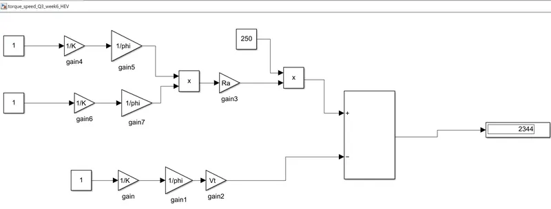
ω= V/(Kϕ)-Ra/(((Kϕ)^2)) .T is the torque and speed characteristics of DC motor.
So the inputs are as shown:
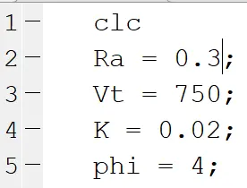
For the above input, the output is 2344 rad/sec.
4. Given below are the differnce between the inuduction and brushless motors.
| AC INDUCTION | BRUSHLESS DC |
| In case of AC Induction motor, it does not have any magnets on the rotor, but it have staked lamination with series winding. | Here the rotor has PM (permanent magnet) |
| When 3 phase power is applied to the stator of motor, an RMF (Rotating Magnetic Field) is created.. This RMF is linked with the rotor winding and creates its own rotor current. This rotor current which has its own magnetic field interarct with stator RMF and generates torque. |
In this case, the magnetic field of PM interact with the stator magnetic field. So that creats its own torque. |
| As the AC induction have winding, the magnetic field can be adjusted by using VFD (Variable frequency drive) and Variable Frequency Drive. | Here we cannot vary the magnetic field strength of PM |
| It have Lower peak efficiency but averaga efficiency is much higher. | Here Peak efficiency is high but average efficiency is lower. |
| Stability over the speed torque characteristic is very difficult and controling the temperature. | But here the Stability over the torque speed characteristci is simple. |
| Since the voltages are controlled here to vary the B, Inverter are used for frequency and voltage control. | But in this case, we cannot vary B. So no use of inverter here. |
| As size of the motor increase, the efficiency doesnot change much. | But here, as the size of the motor increases, the efficiency of the motor drops accordingly. |
| Cost wise AC induction is better | In case of DC brushless motor, we use PM which is very costly, so we Brushless DC motor is costlier. |
Stator construction is same in both AC induction and Brushless DC motor