Week-7 Challenge: DC Motor Control
1A.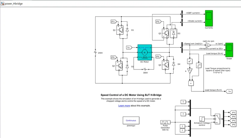
BLOCKS USED:
IGBT:
It is a semiconductor device controlled by the gate signal. Since IGBT contains Snubber circuit, it is a series combination of a resistor (Ron), inductor (Lon). So the switch is operated based on the value of gate signal also snubber circuit is connected in parallel to the IGBT.
When Vce and Vg >0 it is ON state.
When Vce > 0 and Vg = 0, then it is OFF state.
Diode:
If voltage at anode is greater then cathode voltage then it is Forward Bias condition. At that time it act as short circuit path with low resistance and also with cut in voltage. In the other hand, If anode voltage is less than cathode voltage then reverse bias (i.e) open switch.
DC MOTOR:
The block for it consist of 3 segments – armature circuit, field circuit and torque input- output measurement signals. We have given motor ratings as 5 HP, 240V, 1750 RPM. Fan type model is used so that T=kW^2. The armature voltage is varied from 0 to 240 V by changing the duty cycle Duty cycle is varied by Pulse width generator block.
Here we use DC motor to rotate in Clockwise and anti-clockwise direction with varied speed.
When the junction BE and BC are forward biased BJT or IGBT act as ON switch in Saturation mode.
In case of H-BRIDGE it consist of 4 transistors, with each one having parallel snubber circuit.
When Q2 and Q3 are conducting and D1 and D4 are freewheeling, motor spins in one direction. When Q1 and Q4 are conducting, D2 and D3 are freewheeling, motor spins in other direction.
Speed of the motor is controlled by using the field winding excitation across the rotor winding. (i.e) 300V.
1B. How to reduce the current shoot up in the scope:
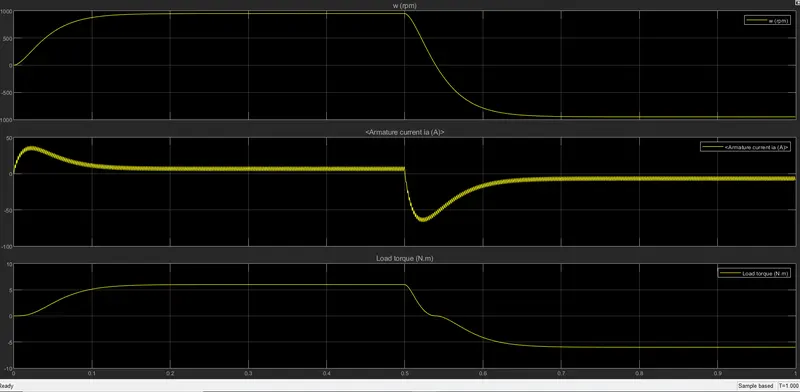
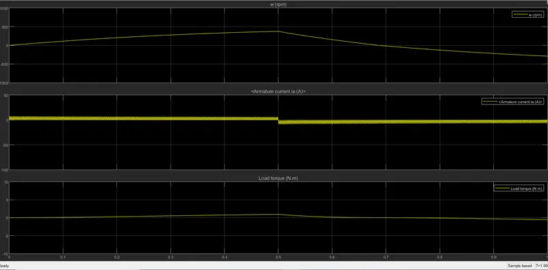
When motor rotates in a particular direction at constant speed, there is no spike. Once the direction is reversed the armature current (ia) spikes up initially then later on it becomes normal. As the armature voltage is reversed, it rotates in opposite direction.
In the above case the duty cycle is 75%. In that case, for 75% of the time the motor is in one direction. During remaing 25% of the time, the supply is off, so that the charge in the inductor gets discharge in the free wheeling path. So this sudden change in armature current caused the spike. (also armature voltage is also reversed ).
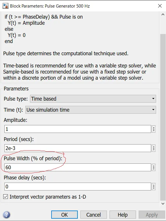
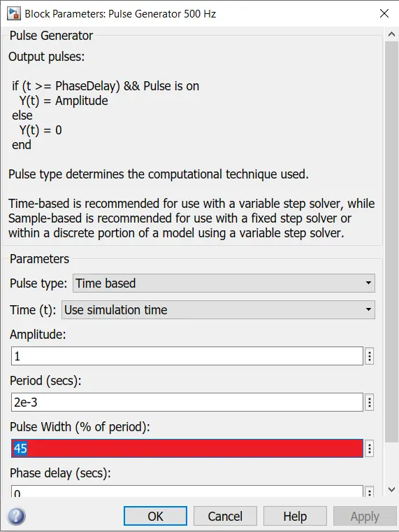
Now we shall decrease the duty cycle as 60%. So the spike is reduced as compared before.
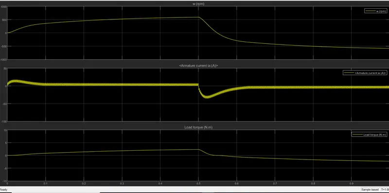
Now further decrease the duty cycle to 45%. The spike is almost reduced. So as the duty cycle gets reduced the spikes of armature current is also gets reduced .
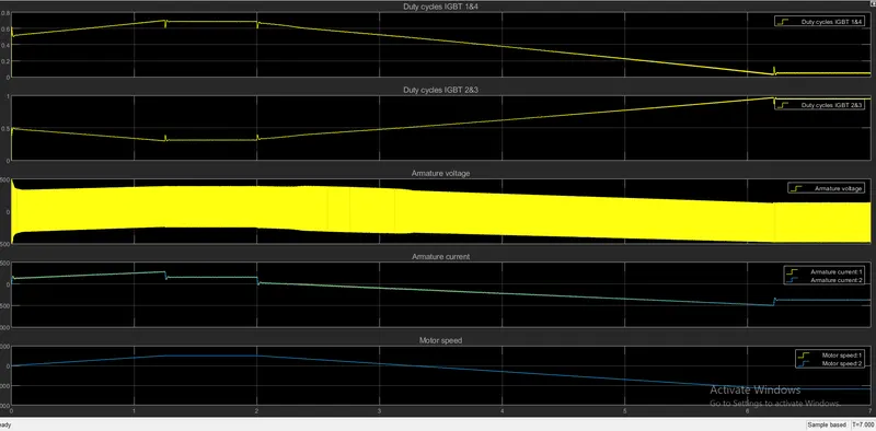
1C. Here closed loop speed control is done with four quardrant operation. The closed loop speed controller will give the output as armature current from the DC motor…using PI current controller , the chopper duty cycle (D) for the corresponding commanded armature current. Then this duty cycle is compared with sawtooth carrier signal to obtain the PWM signal required forn the chopper operation.
Here we are using four quardrant operation which has the following advantage (ie) forward motoring, forward breaking, reverse motoring , reverse breaking. In case of motoring the power output is positive and vice versa incase of breaking. An example of four quardrant operation is hoist drive.
The simulink of DC7 four quardrant drive contains a speed controller, a current controller, a regulator switch, a chopper and a DC motor.
SPEED CONTTOLLER BLOCK
The inputs to the block is speed reference and the motor speed , and the output is current refernce. This current reference is used for the current controller block which inturn obtain the electromagnetic torque to reach the desired speed.
CURRENT CONTROLLER BLOCK
This is a PI current controller block. The inputs to this block is the current reference and the armature current flowing through the motor, the output is reference current error for PWM pulses.
REGULATION SWITCH BLOCK
It consist of DC machine, torque controller model and a simulink switch model. The switch model is used to select the regulation mode (ie) torque or speed regulation.
CHOPPER BLOCK
It can be modelled as half bridge or full bridge convertoe model. It has two operating modes which deoends on the DC motor drive ( 2 or 4 quardrant operation). The output of this block is the desired armature current for Dc motor. A smoothing inductor is connected in series with chopper to avoid sudden surge in current fluctuation.
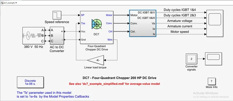
We can go for any kind of input to the drive which is torque , speed or rotational input. Here we use torque as mechanical input.
| DC 7 DRIVE MODEL | H- BRIDGE MODEL |
| Here supply is AC with 50hz and is converted to DC. | Here supply is in DC. |
| Here the duty cycle correspond to the commanded armature current given through PI controller. | The duty cycle is given through pulse generator which is manually entered. |
| Armature current waveform has low ripples as it works in a closed loop manner. | Here the aramture current waveform has more ripples as the D is eneterd manually. |
| Powe GUI is discrete in case of DC7 model | Power GUI is continuous in case of H-Bridge. |
| Both load torque and speed is taken as referance. | But here only Load torque is taken as referance. |
2. For 2 quadrant chopper, it cosist of 2 controlled and 2 uncontrolled switches.
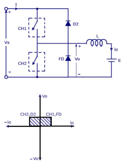
Initially, current flows through CH1 to the load(motor) and also charge the inductor present in the load. Once the CH1 is off, Charge stored in the inductor freewheels through FD to the motor load. After the stored charge is discharged fully, CH2 is ON, during that time negative current flows from load to source via CH2.
E=Vs initially during CH1 but Vs=E during CH2 is ON. During discharge (i.e) freewheel, E=0.
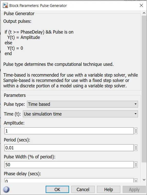
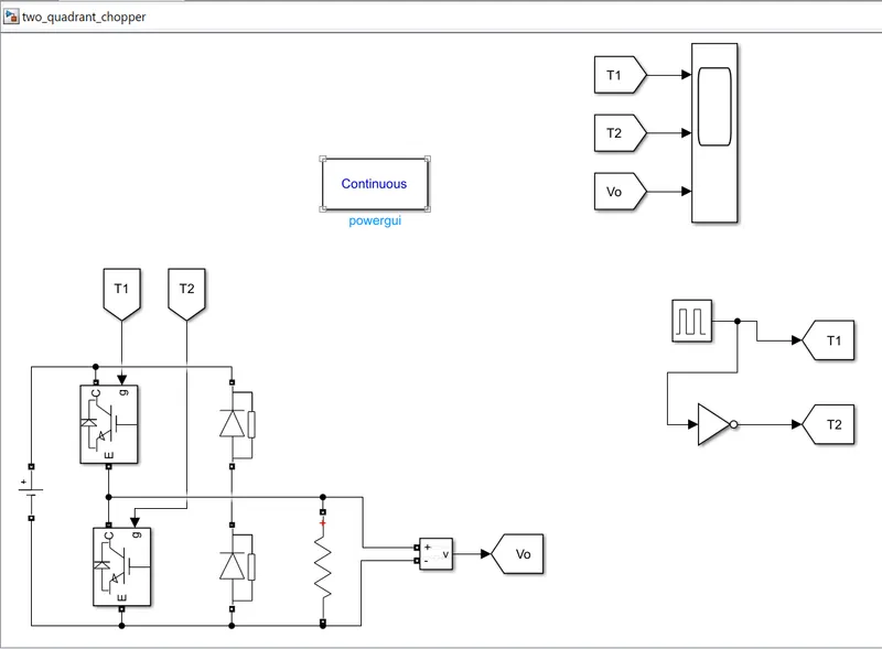
CH1 is operated for 50% of the time and the remaing 50% of the time is operated with CH2.
Input DC voltage is 240v. Blocks used are,
IGBT, Diode, Voltage source, voltage measurement, pulse generator, from and goto blocks, Scope, NOT gate.
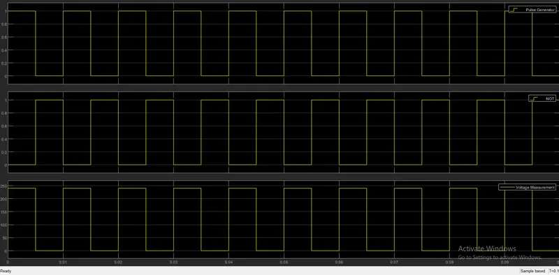
As the load is resistive, the output waveform is:
3.
In brushless DC motor which is electronically commuted based on hall position sensor does not have any brushes for its commutation . Incase of brushed DC motor the permanent magnets is outside and the electromagnet is inside. These electromagnet provide the magnetic field in the armature and helps to rotate the armature.
The basic working principles of both brushed and brushless DC motor are same ie. Internal shaft position feedback. When none of the coil is energised, rotor remains stationary. Out of three phases, 2 phases has to get supply at each commutaion step. So that it creat the torque. for rotation. BLDC is controlled by trapezoidal controls. As pole pair increases, the frequency of commutation increases. For proper commutation we need to know the correct position of the rotor using 3 Hall sensors present.