Week 4 Challenge
1). Define tooling direction
The Tooling Direction is the direction that the mold pulls apart. The mold is built into two separate pieces. You have a Cavity side and you have the Core side. The Core pulls apart from the Cavity and that's the Dyeline or the Tooling Direction.
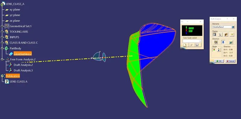
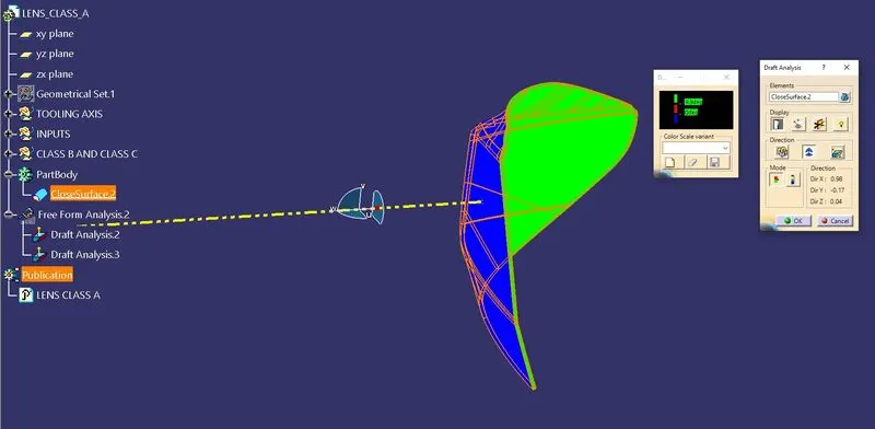
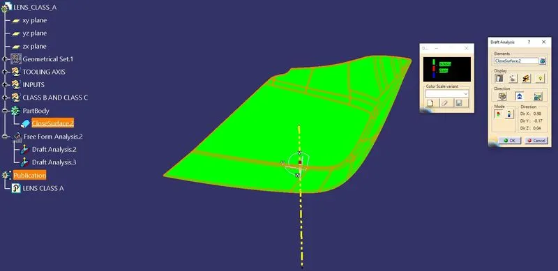
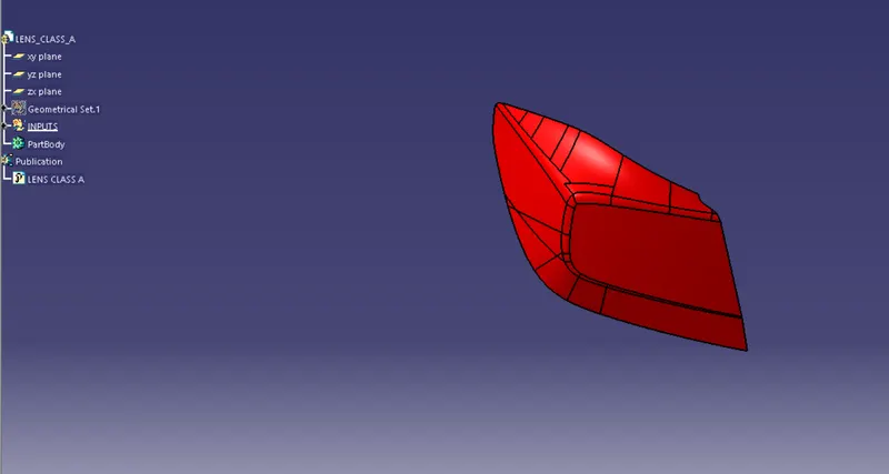
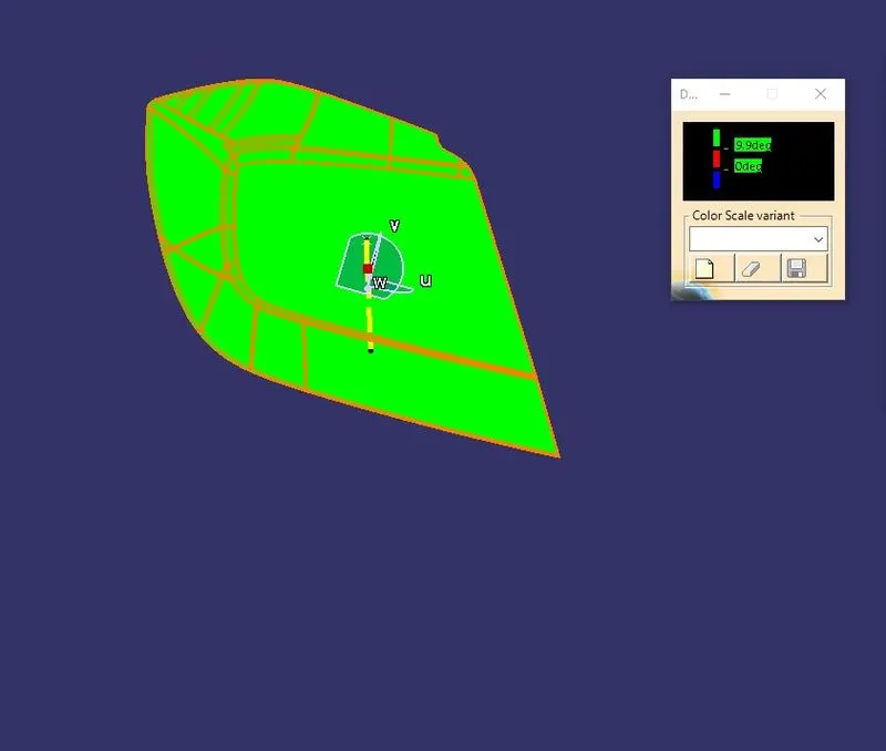
2). Create tooling direction for Class A with 10 deg draft ( draft in command should be 10 deg) and show the draft analysis
3). Write the definition of Parting line
A parting line, in the industrial casting of molds, is the borderline in which draft angles change direction. One can check the parting line in the mold or product which divides the two half, i.e; the core and the cavity of a molded part. It is sometimes a starting point for the mold parting surface. In engineering drawing, a parting line is often abbreviated as PL. ASME's Y14.8 standard specifies a symbol for the parting line. Engineering applications (seals, tight running molded parts) that require precision for shape control, call for the removal of flashes. Many molders will repair or even replace the mold tooling so that the flash is reduced to an acceptable tolerance or eliminated. Secondary operations to remove parting line flash include hand trimming, vibratory tumbling, media blasting, and cryogenic deflashing.
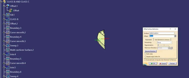
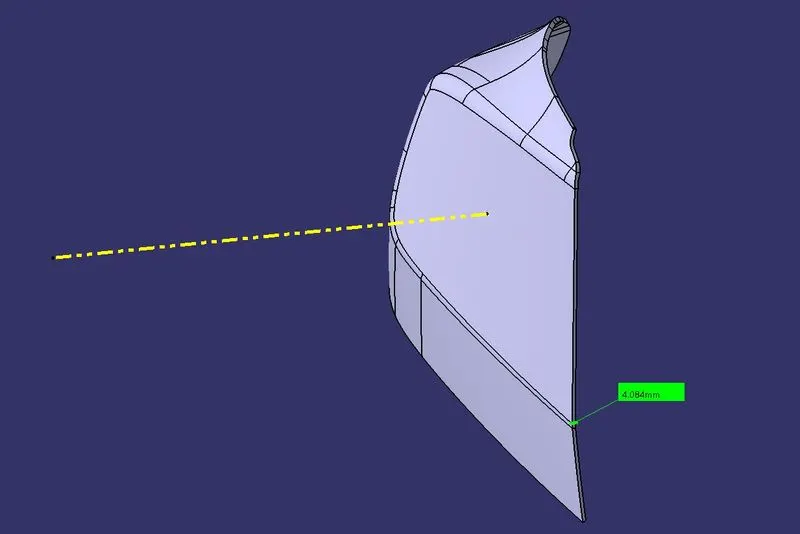
4). Create B surface of the given lens in surface modeling (not in part), with 4 mm thickness
5). Create a parting line for thickened Lens
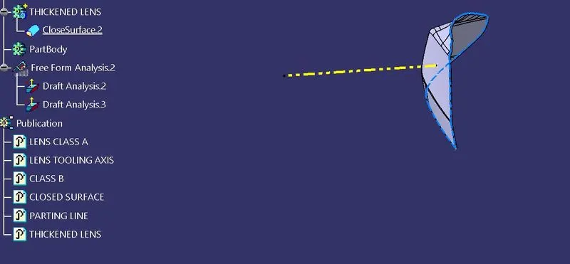
6). Prepare a report on how you have created the part and how did you approach creating a parting line and doing draft analysis
PROCEDURE:
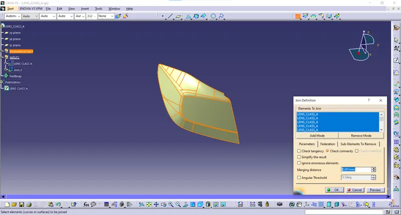
- Downloading the given inputs and performing a surface check by Join
- Creation of tooling axis for a draft clearance of `10^o`.
- Creation of draft analysis for Class A.
- Since the surface consists of styles fillets so the class A surface is directly offset for 4 mm.
- Creation of Sweeps concerning the Draft direction and trimming the Class A, Class B, and Class C to form a closed surface.
- Adding thickness by close surface in part workbench.
- Creation of draft analysis for the close surface.
- Creation of parting line on the edges of the Class A surface since the draft on the Class B and Class C is negative so this is the reason behind selecting the part lines on edges of Class A.