Week - 4
MODEL 1:
AIM:
'To implement control logic of a washing machine using stateflow in simulink'
OBJECTIVE:
To implement a control logic of a washing machine using stateflow in simulink as per the given sequence:
- If the powewr supply is available ,the system gets activated.
- If the water supply is available,stop the process and indicate through LED.
- Soaking time should be 200s followed by washing time of 100s.
- Then rinsing happens for next 20s and dryer runs for 50s.
After all the processe have completed turn on the finished LED.
BLOCK DIAGRAM: In block diagram the challenging task is to connect the lamp with the output.To connect the lamp with output double click on the lamp and the select the connect option and then click on the line where we want to connect.
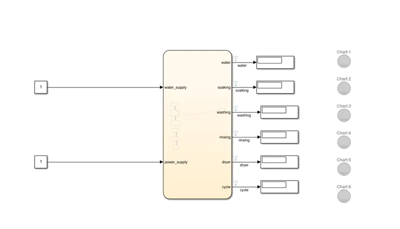
#block diagram when water supply is on and animation is on:
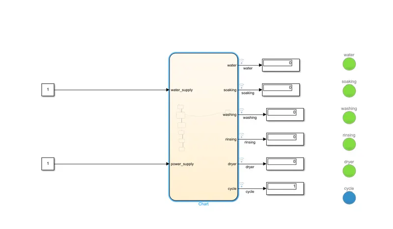
In this chart we are going to use the aninmation.To see the how chart is executting we are using the animation .
To make the animation first open the chart and go into dispaly -animation-medium/fast/super fast as you want.
CHART DIAGRAM:
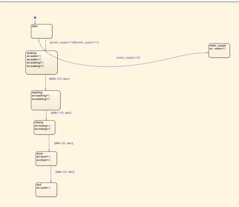
In this chart
en =entry
ex =exit
here we have to increse the simulation time for exicution of all the process
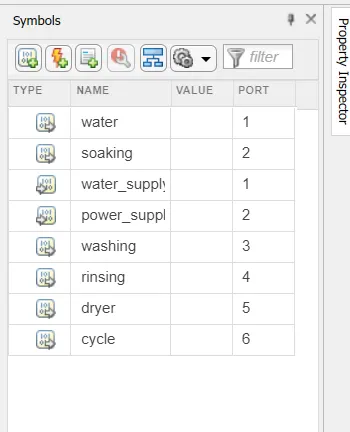
PARAMETERS:
here power supply nad water supply arev the inputs and other 6 are output .
SIMULATION TIME PARAMETERS:

CONCLUSION:The simulation of the Washing machine using state flow is done and the result is satisfactory.
**********************************************************************************
MODEL 2:
AIM:
'To make a simulink chart for the "GEAR SHIFT"logic.'
OBJECTIVE:
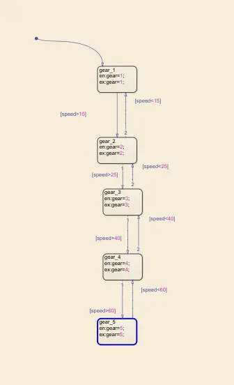
Making a simulink chart for the gear shift for the bellow mentioned parameters:
Speed range(kmph) gear
0 -15 1
16-25 2
26-40 3
41-60 4
Above 61 5
CHART DIAGRAM:Here we have to give input and output conditions for each chart.If
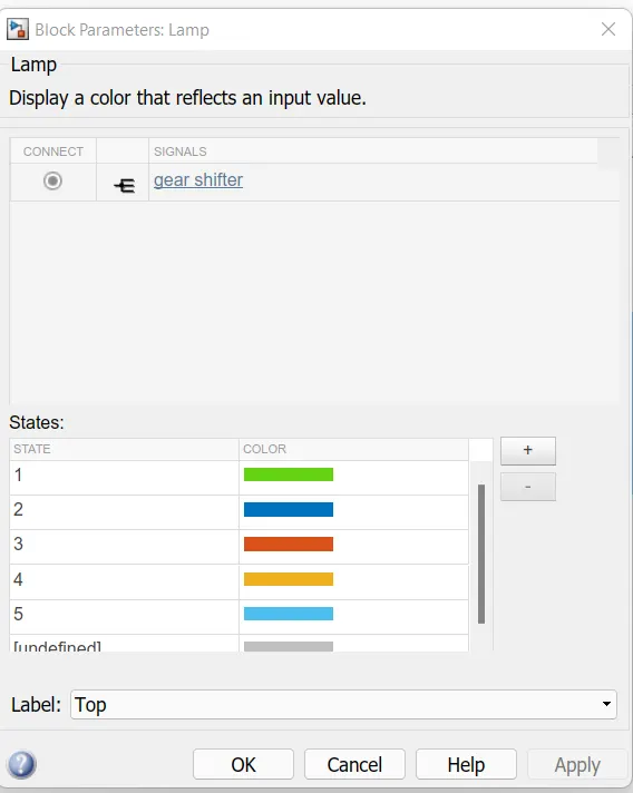
Lamp settings:
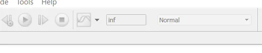
SIMULATION TIME PARAMETERS:
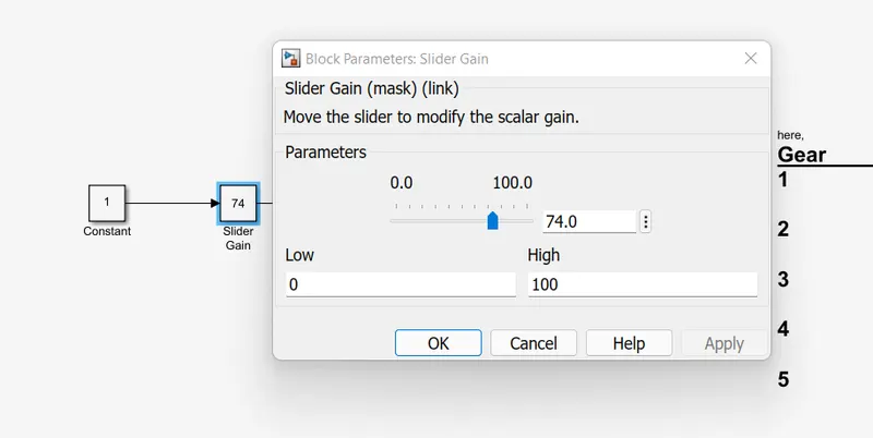
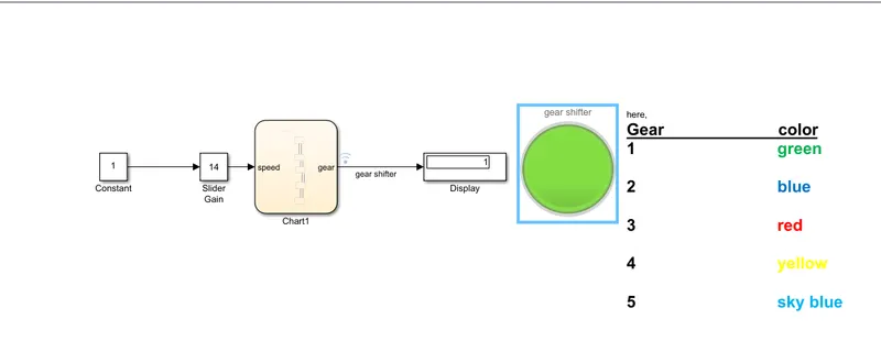
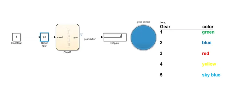
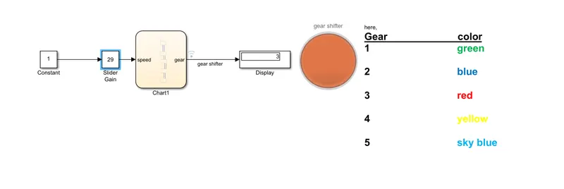
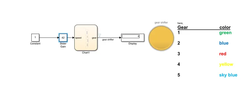
INPUT:In slider gain move that curser to get required output .
OUTPUT:we get the output in the form of lamp and also in display.
GERA 1:
GEAR 2:
GEAR 3:
GEAR 4:
GEAR 5:
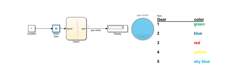
CONCLUSION:
- Create a State Flow for Gear Shaft using Simulink and the results are satisfactory.