Week 3 - External flow simulation over an Ahmed body.
AIM: The main aim of the challenge is to observe the velcoity , pressure and drag changes in ahmed body simulation as this is a research model and later can be used for validation puposes.
OBJECTIVES:
Run the simulation for the velocity of 25 m/sec with the default air properties in fluent.
For this challenge, you will have to provide answers to the following questions:
Q1. Describe Ahmed's body and its importance.
Q2. Explain the reason for the negative pressure in the wake region.
Q3. Explain the significance of the point of separation.
To generate velocity and pressure contours for the results obtained by three different meshes for grid independence test.
To generate drag coefficient plots and lift values for all the cases.
THEORY:
Q1. Describe Ahmed's body and its importance.
The Ahmed body is simplified car body used in automotive field to study the impact of the flow pattern on the drag. The external aerodynamics of the car defines many major traits of an automobile like stability, comfort and fuel consumption at high speeds. The flow around the vehicle is characterized by high turbulent and three dimensional flow separations as well as there is a growing need for more insight into the physical features of these dynamical flows. The Ahmed Body is a simplified car, used in automotive field to investigate the flow analysis and find the wake flow around the body. Ahmed body is made up of round front part, a moveable z slant plane in the rear of the body to study the detachment phenomena at different angles, and a rectangular box which link the front part and the rear slant plane. The principal objective to study such a simplified car body is to tackle the flow processes involved in drag production. Through perceiving the mechanisms involved in creating drag one can be able to design a car to minimize drag and therefore reducing fuel consumption and maximize vehicle performance.
Importance of Ahmed body:
An Ahmed body represents a simplified like vehicle volume which helps understand the fundamental physics defining by the engineers the lift and drag forces and coefficients at certain characteristically velocities, pressure differences, and seeing and analyzing the vortices, turbulence and Reynolds number obtained. ANSYS is a general purpose FEA and CFD simulation software. It gives numerical prediction of the behavior of a system.
These numerical predictions need to be validated by experimental data. People working in vehicle aerodynamics use Ahmed body to validate their numerical model because the experimental data from wind tunnel testing is available for Ahmed body. Once the numerical model in validated, it is used to design new models of the car.
Its shape is simple enough to allow for accurate flow simulation but retains some important practical features relevant to automobile bodies. This model describes how to calculate the turbulent flow field around a simple car-like geometry using the Turbulent Flow, k-epsilon and k-omega interface. Later, either experimentally or computationally it can be recreated all the same but with a desired geometry, new to come up to the market or a research.
The Ahmed body was described originally by S. R. Ahmed in 1984 . Three main features were seen in the wake:
- The A recirculation region that is formed as the flow separates at the top of the vertical back surface of the model
- The B recirculation region that is formed due to the separation at the base of the model.
- The c-pillar vortices that form as the vorticity in the side boundary layers roll up over the slant edges.
The wake was shown to be highly dependent on slant angle. For slant angles less than 12°, the flow remains attached over the slant. The flow is essentially two-dimensional and has low drag. Between 12° and 30° the flow becomes much more three-dimensional as the c-pillar vortices form. These reach maximum strength at 30°. The drag increases significantly as the low-pressure cores act on the rear surfaces. Past 30° the flow separates fully off the slant. This results in a sudden decrease in drag and weaker c-pillar vortices.
Q2. Explain the reason for the negative pressure in the wake region.
The negative pressure is due to the velocity difference applied at a certain Reynold number and the rear angle, which at a low Reynolds number when this difference in pressure happens the wake obtained increases the drag due to the pressure drop behind the Ahmed body, which at a high Reynolds number due to the vortices generated it produces small amounts of pressure thrusting the body.

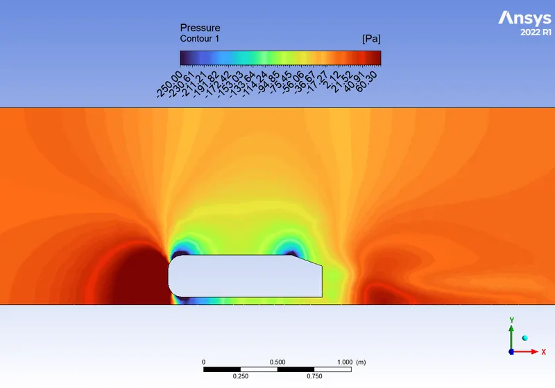
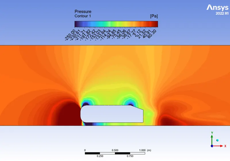
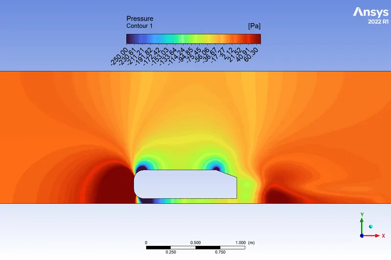
From the pressure contours given in results section we can also observe that the neagtive pressures are not only formed at trail end but at the front two edges also where the velcoity is high and the chances of seperation are at higher velocities which inturn produces very low to negatives pressures.
Q3. Explain the significance of the point of separation.
The point of separation defined by the Ahmed body and the flow, the alpha angle depending on which value is at it causes change in flow direction, forces required, lift on the body, induced drag due to “tip vortex”, at a critical value flow in slant stalls and reduced lift-reducing as well drag, all depending on the value of alfa and the Reynolds number.
GEOMETRY:
Initially a Three dimensional Ahmed body has been loaded into space claim.
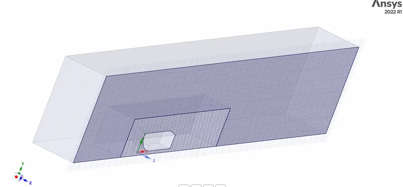
To understand the external aerodynamics around the Ahmed body boundaries should be provided . For that we have to use Enclosure command to generate a rectangular box around the Ahmed body
An Asymmetrical Enclosure has been selected with the dimensions given below
Front – 2m
Back- 5m
Sides and Top – 2m
The Back of the Ahmed body has been provided with 5m In order to capture the wake region.
To Obtain more accurate results the Mesh has to be finer but that increases the computational time as well. So We need go for local refinement. To perform local refinement we need to provide another enclosure around the Ahmed body with
Front- 0.5m
Back -1.5m
Top and sides- 0.5m
Bottom is set to zero in both the enclosure to match the base of Ahmed body.
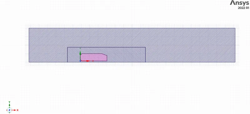
After generating the enclosure an intersection region will be formed between the Large and Small enclosure this should be deleted to avoid the overlapping mesh. This common region can be deleted using Intersection command.
Lastly as this Ahmed body is a symmetrical figure we split the body using split command and use only half of the geometry to reduce the computational time.
MESHING:
During meshing , firstly , the global element size has been set to 100mm for fine mesh .
The Outer Enclosure is filled with hexahedral elements wherever required and for the smooth transition Multizone option was used.
For Inner enclosure sizing has been given by reducing the element size to 30mm for fine mesh.
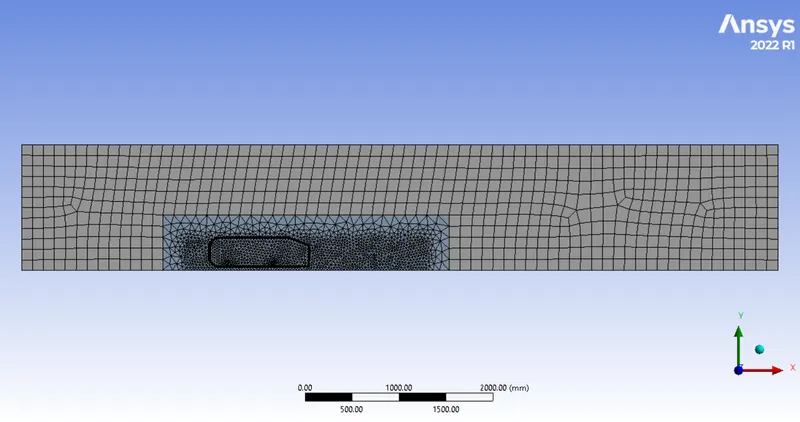
After that the handles of Ahmed body are refined separately using face sizing and has given a value of 5mm to obtain a circular shape mesh elements.
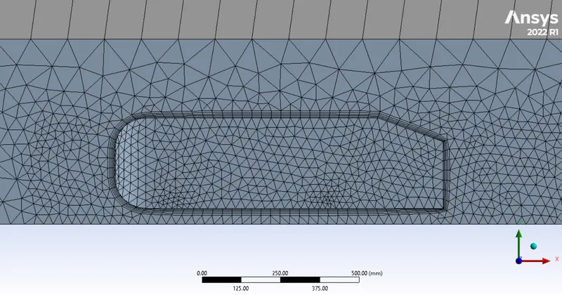
At the end Inflation have been provided to capture the near wall region better. In this challenge we have to calculate the value of drag coefficient, which requires better wall capturing. For fine mesh Y+ value of 50 is used which results in first layer thickness of around 1.5mm . Five layers are inputted with growth rate of 1.2. Now the mesh has been generated and exported to Fluent after Naming all the required boundaries.
FLUENT SETUP:
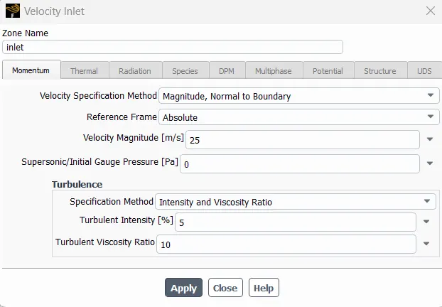
Model , Fluid properties details are provided below
Fluid properties:
Working fluid = Air at temp of 288.16 K
Velocity of the air = 25 `m/s`
Dynamic viscosity of the air = 1.7894 `(kg)/(m.s)`
Density of the air = 1.225`(kg)/m^3`
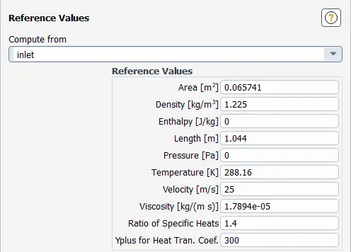
Geometrical characteristics:
Total length of the Ahmed body `L_c`= 1.044 m
Projected area (A) = 0.06574 `m^2`
The simulation set-up will be using different Y+ values and mesh with K-epsilon turbulence model. Steady-state analysis is performed as the matter of concern is the end result.
| Cases | Y+ value | Turbulence model | Mesh |
| Case 1 | 200 | K-epsilon (Realizable with Standard wall functions) | Coarse |
| Case 2 | 100 | K-epsilon (Realizable with Standard wall functions) | Medium |
| Case 3 | 50 | K-epsilon (Realizable with Standard wall functions) | Refined |
WHY NOT K-OMEGA AS A TURBULENCE MODEL?
- The K-omega model is well suited for low Reynolds number which accounts for compressibility and shear flow spreading.
- However k-omega (SST-Shear Stress Transport) can be used in this case because of it's capability to incorporate high Reynolds number flows. As it uses K-omega in the inner region of the boundary layer and high Reynolds number model i.e K-epsilon in the outer region of the boundary layer.
- The mesh refinement is an important aspect in K-omega model as it accounts for near-wall effects. The Y+ values should be in the range between `1leY+le10`. Mesh refinement should be much fine enough to capture near-wall effects. Accordingly, it uses extensive computation resources for such fine mesh refinement.
- Therefore it is better to opt for K-epsilon as it uses wall functions to estimate near-wall effects and is well suited for higher Reynolds number flows. Comparatively it is computationally cheap which can work with `30leY+le300`. This certainly gives mesh refinement flexibility to compute near-wall effects.
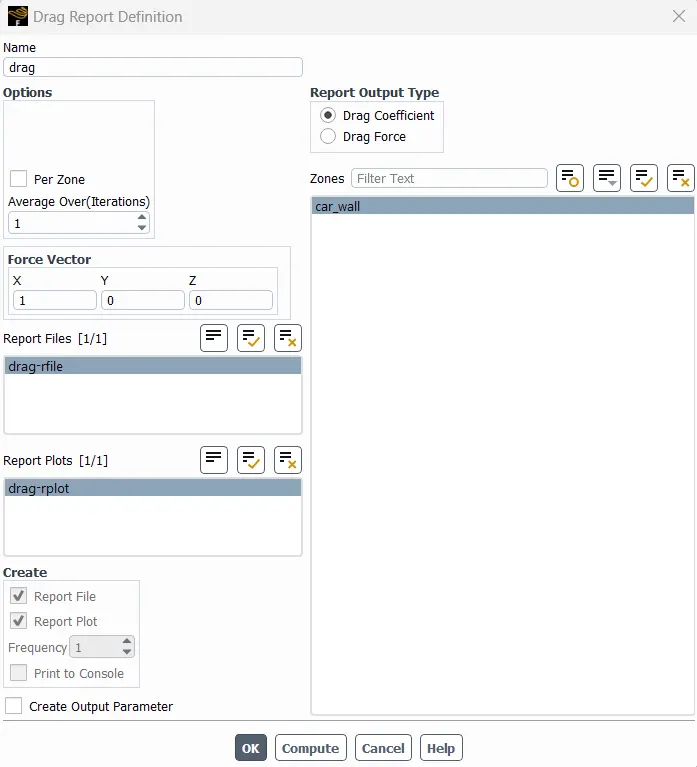
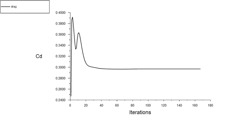
Inorder to observe the convergence of drag coeffcient a report defintion has been generated below simulation is run
Now Simluations are run for three cases coarse,medium and fine meshes and the results are extracted and presnted below.
RESULTS:
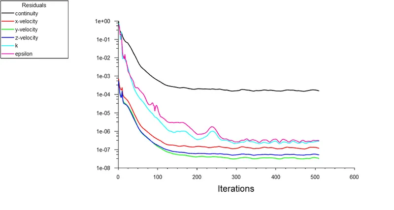
Coarse( 110007 elements) :
Residual plot :
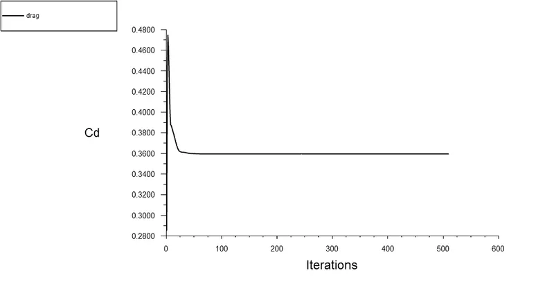
Drag Coefficient Plot :
Pressure Contour:
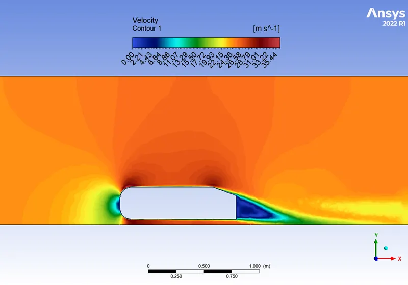
Velcoity Contour :
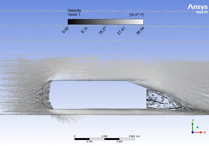
Velocity Vector:
Medium(286086 elements):
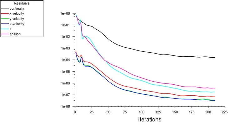
Residual Plot:
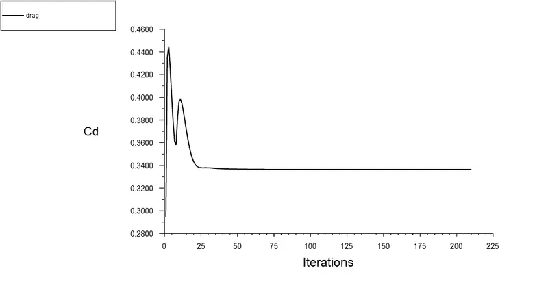
Drag Coefficient Plot:
Pressure Contour:
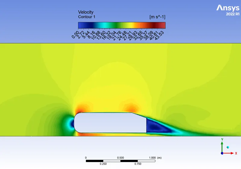
Velocity Contour:
Velocity Vector:
Fine( 627805 elements):
Residual Plot:
Drag Coefficient Plot:
Pressure Contour:
Velocity Contour:
Velocity Vector:
Mesh Type drag co-efficient(Cd) Lift co-efficient(Cl)
Coarse 0.359 0.264
Medium 0.336 0.203
Fine 0.297 0.237
From the above details of contours , plots , tables we can extract the following details
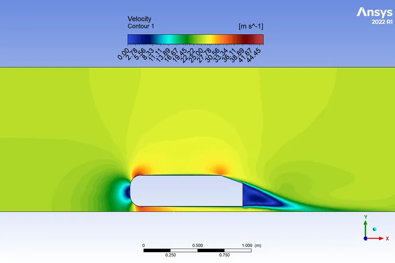
The Medium mesh provided the more accurate result compared to coarse and fine mesh ( based on the given data)
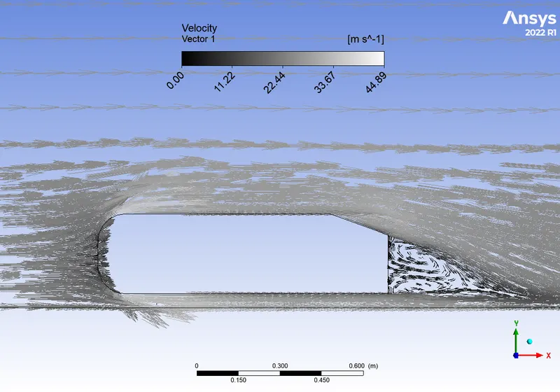
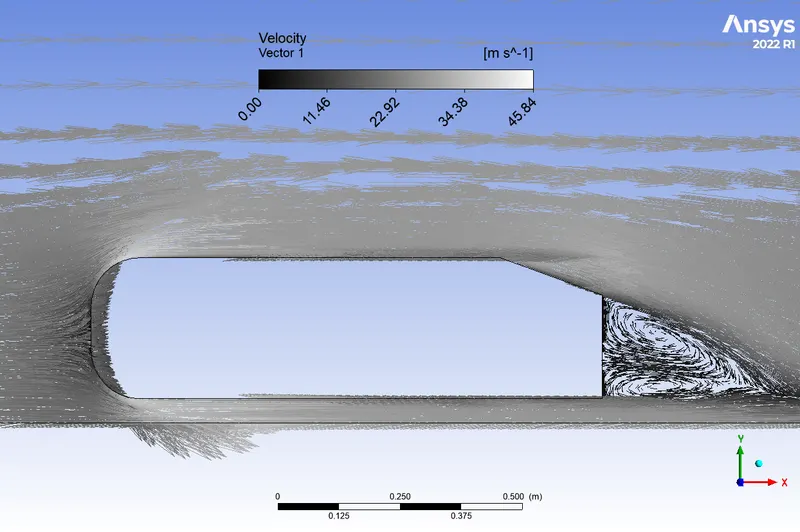
From the velocity and pressure contours we can observe that the velocity is high the edges of the Ahmed body and inturn the pressure is lower that those regiones.
After the trail region the flow starts to recirculate which is clearly captured by vector plots.
CONCLUSIONS:
The baseline mesh gave a poor result, it wasn't able to capture the flow around the Ahmed body and the wake structure, due to coarse mesh.
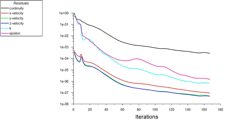
The medium mesh gave better results. The plots show the wake formation accurately and the flow around the Ahmed body was also captured pretty well.
There is a variation of pressure across the Ahmed body. The pressure in front of the body is positive because that's the location where the flow first comes in contact with the body and comes to rest. At the corner, the flow accelerates, thereby decreasing the pressure.
The reason behind negative pressure in the wake region is due to flow separation, recirculating flow. It's a phenomenon that generally happens as the air moving past the body isn't able to pass through the immediate backside of the body creating a region, where there is no movement of air and thereby creating a pressure gradient.
As the wake flow is the main contributor to the drag force(pressure drag), the point of separation is an important aspect of the flow. The more attached the flow is to the body the recirculation zone will be smaller and hence reduce the adverse effect of pressure drag, improving the fuel efficiency of the body.