Week 3 - External flow simulation over an Ahmed body.
External flow simulation over an Ahmed body
Ahmed Body and its importance :
This benchmark model was designed to make baseline analysis for understanding of aerodynamic quantities like drag forces acting over the surface of the car. Main aim of the aerodynamics engineer is to make sure that flow over the car doesn't seperate too much which creates an adverse pressure gradient creating a negative pressure which sucks more and more air to hit the front face of the car!
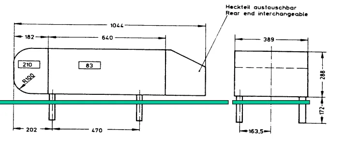
The Ahmed Body was first created by S.R. Ahmed in his research “Some Salient Features of the Time-Averaged Ground Vehicle Wake” in 1984. Since then, it has become a benchmark for aerodynamic simulation tools. The simple geometrical shape has a length of 1.044 meters, height of 0.288 meters, and a width of 0.389 meters. It also has 0.5-meter cylindrical legs attached to the bottom of the body and the rear surface has a slant that falls off at 40 degrees.
Solution 2)
Explain the reason for the negative pressure in the wake region
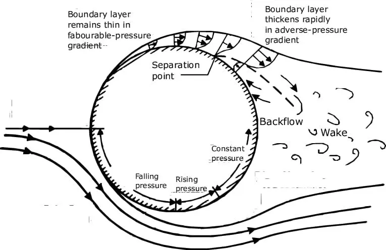
Air after passing the stagnation with nearly 0 velocity, now accelerates from centre to the midpoint of the cylinder due to the favorable negative pressure gradient. Along the flow over the surface of cylinder, boundary layer is developed which is the layer where the velocity is comparably lower than the global free stream velocity, because this is the layer where frictional resistance due to viscosity comes into picture.
Velocity reaches a maximum value at the midpoint of the cylinder, with least thickness of boundary layer, indicating least resistances.
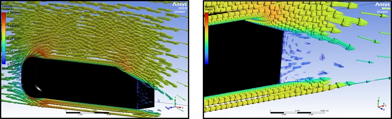
From here on this point, adverse effects of pressure gradients comes into picture. Till Umax">Umax, pressure gradient was the factor which drove to accelerate the flow over left half side of the cylinder. After Umax">Umaxpoint, pressure now starts its journey in a positive pressure gradience. Pressure increases so bad that it actually starts resisting the flow, and flow begins to move in the reverse direction which is called Recirculation region
Solution 3)
Explain the significance of the point of separation
This leads to a point where forward directed flow and reverse directed flow meet at a point where velocity is 0, and pressure again is high which is called stagnation point for boundary layer seperation, which lifts the flow to move in the upward direction. This is the point of flow seperation from boundary layer.
Understanding the Seperation Point
FRAME 1 :
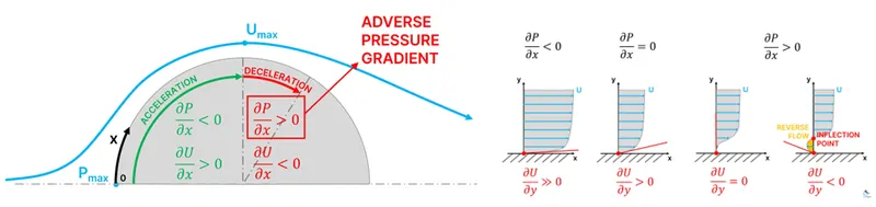
Considering air flowing from negative x axis towards positive x axis with origin of the axis begins from the surface of the cylinder. The first point of contact for air being the centre of the cylinder is a point where air nearly stops which was carrying a momentum before. This point is caled the Stagnation point where the pressure increases to maximum which we can denote it as Pmax">Pmax
.
FRAME 2 :
Air after passing the stagnation with nearly 0 velocity, now accelerates from centre to the midpoint of the cylinder due to the favorable negative pressure gradient. Along the flow over the surface of cylinder, boundary layer is developed which is the layer where the velocity is comparably lower than the global free stream velocity, because this is the layer where frictional resistance due to viscosity comes into picture.
Velocity reaches a maximum value at the midpoint of the cylinder, with least thickness of boundary layer, indicating least resistances.
From here on this point, adverse effects of pressure gradients comes into picture. Till Umax">Umax
, pressure gradient was the factor which drove to accelerate the flow over left half side of the cylinder. After Umax">Umax
point, pressure now starts its journey in a positive pressure gradience. Pressure increases so bad that it actually starts resisting the flow, and flow begins to move in the reverse direction which is called Recirculation region
This leads to a point where forward directed flow and reverse directed flow meet at a point where velocity is 0, and pressure again is high which is called stagnation point for boundary layer seperation, which lifts the flow to move in the upward direction. This is the point of flow seperation from boundary layer.
Geometry Enclosure Creation :
Creating enclosure 1
Go to Prepare > Enclosure > Click on the Body > Symmetry condition to be turned OFF > give right dimensions
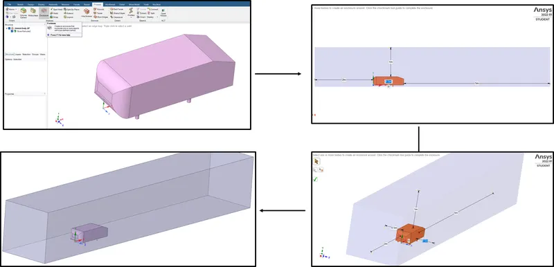
Lets create enclosure 2, to reolve teh meshing for capturing graidience of physics like wake region, boundary layer seperation (Flow Seperation).
This inturn reduces no of finr grid cells required for the outer enclosure inturn reducing reducing computational cost
Creating enclosure 2
Go to Prepare > Enclosure > Click on the Body > Symmetry dimensions condition to be turned OFF > give right dimensions
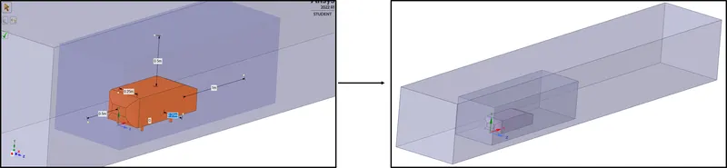
Creating 3-D Plane for the body
Go to Design > Plane > Click on the xyz axis for displaying all three planes
Split Body
Since the body is symmetric in nature, we can simulate for one half of the body! Lets cut the whole enclosure with body using Split Body command.
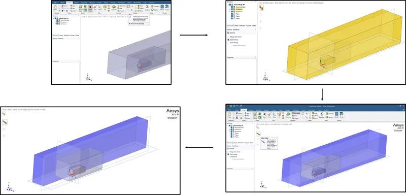
- Go to Design > Split Body > Click on the Enclore 1 > Select the target (Enclosure 1) > Select cutter > Select regions to remove
- Go to Design > Split Body > Click on the Enclore 1 > Select the target (Enclosure 2) > Select cutter > Select regions to remove
- Go to Design > Split Body > Click on the Enclore 1 > Select the target (Boss-extrude2) > Select cutter > Select regions to remove
After splitting all the enclosures and body, one can see this way
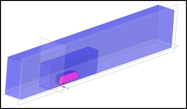
Check for area interferences by selecting the XY plane and clicking on section plane
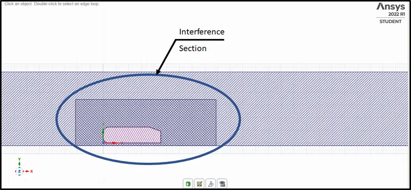
Lets solve this interference by
Go to Prepare > Intereference > Click on the right arrow (green)

Right Click on the Boss Extrude2 > Supress for Physics !
Share Topology :
Share topology option is ON when two or more enclosures are present and information of physics must travel from one closure to other and then the body.
Now Go to Workbench > Select the whole body by drag and select > Click on share
Meshing :
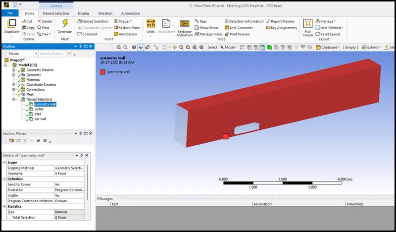
Creating named selections :
- Click on all the faces of enclosure except Inlet, outlet and ahmed body > click N > name it Symmmetry wall
- Click on face of Inlet > click N > name it Inlet
- Click on face of Outlet > click N > name it Outlet
- Choose Box Select > Drag and select Ahmed Body > name it car wall
Running meshing :
Idealogy
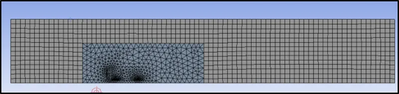
One can save computational cost wherever there are regions where no curvatures in profile are present. One can use Hexahedral mesh for ease in calculation of properties in outer enclosure and use tetrahdrons for inner enclore where curvature of ahmed body is present.
One can do this operation by using Multizone meshing
Lets first run a base line mesh of 0.1m/100mm element size of Tetrahedrals all over the body
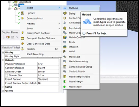
Right Click on Mesh > Insert > Method > Select outer enclosure as geometry and apply > Go to Method > Choose Multizone
We now run 4 cases of simulation:
- Inner Enclosure element size = 50mm
- Inner Enclosure element size = 40mm
- Inner Enclosure element size = 35mm
- Inner Enclosure element size = 25mm
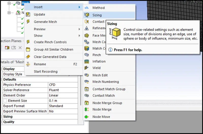
Go to Mesh > Insert > Sizing > Select inner enclosure > Element Size = 50mm > Update Mesh
But once after meshing with inner enclosure of element size 50mm, we can clearly see that Ahmed body legs will not be captured, because the diameter of teh ahmed body legs itself is 10mm, so one has to mesh seperate sizing for Ahmed body legs
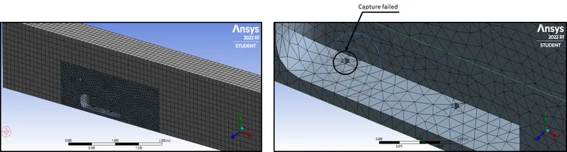
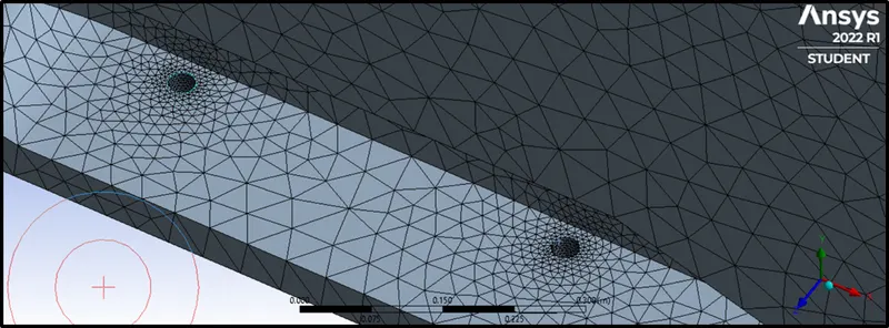
Go to Mesh > Insert > Contact Sizing > Single Box select / face select > Select both faces of legs of Ahmed body > Enter the element size as 5e-3m or 5mm
Capturing near wall physics :
Calculating y+ usinng y+online calculators
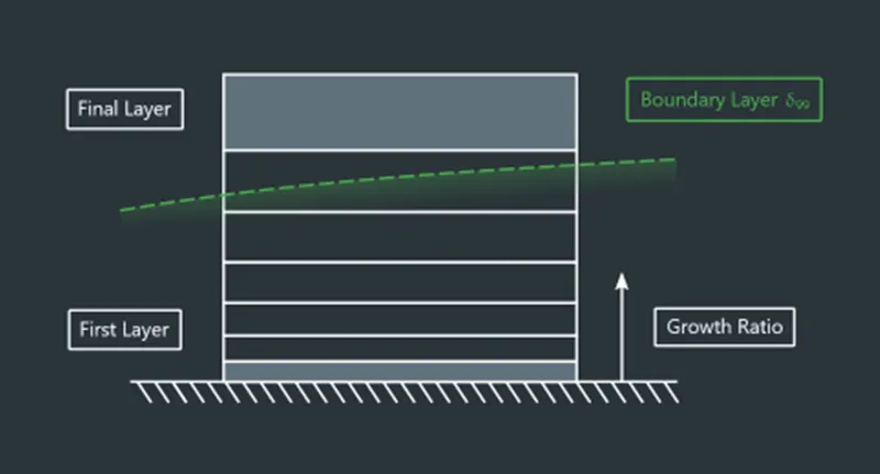
For capturing near wall physics :
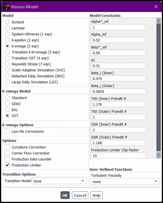
Turbulence model used is k-omg (SST) model with y+ ranging from 1<y+<5
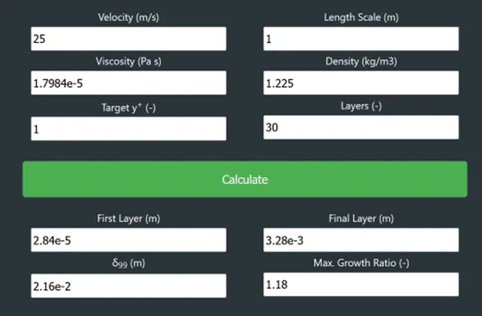
Setting up inflation layer based on the data from first cell height calculated above
Go to Mesh > Inflation > Use Automatic Inflation > Choose "All faces in chosen named selection" > Go to named selection > Choose car wall > Go to inflaion option > Choose first layer thickness > Enter / define first layer height as 2.83e-5m > No of layers =30 > Growth ratio = 1.18
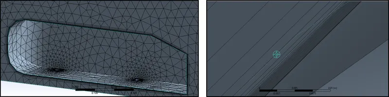
Note down the no of cells in statistics and close MESHING.
NOTE:
One who is using an academic licensing from ANSYS cannot cross 0.5M cells for fluent simulation!
Solving :
STEP 1 : Check Mesh
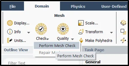
Go to Domain > Check > Perform Mesh Check > Check Console for operation of mesh check
STEP 2 : Physics Setup
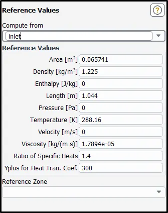
1) Reference Values
How to calculate Projected area of Ahmed body
Go to Outline view > Results > Reports > Projected Areas > Select car wall > X direction
2) Viscous Model has to k-omg(SST) Model
3) Boundary Conditions
Inlet = 25m/s
4) Solution Method
Coupled Solver
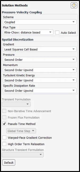
5) Go to Residuals > Turn OFF convergence parameters
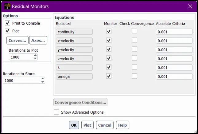
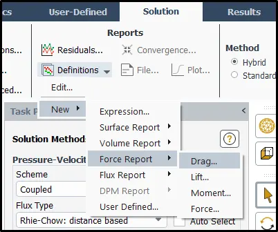
6) Create Report Definition for calculating Drag and lift over the car wall
Solution > Definitions > New > Force Report > Drag >....
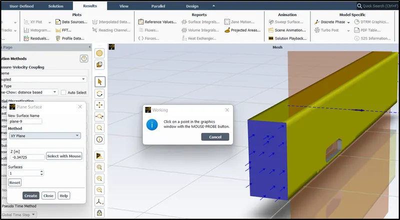
7) In order to observe contours,
Go to Results > Surface > Create > Plane > XY Plane > Select with mouse and drag it to the edge of the section
8) Solution Initialization using Hybrid Potential flow solver
9) After Initialization
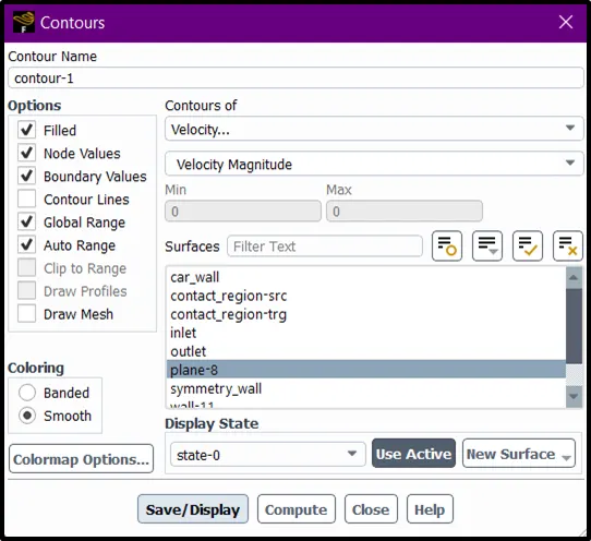
Go to Results > Contours > Select Contours of Velocity > At Surfaces of Plane created > Choose an active display state with XY Visibilty > Save
Similarly for pressure Contour
10) Go to Solution > Run Calculation > No of Iterations = 250 . Hit Calculate
Running simulations for different case setups
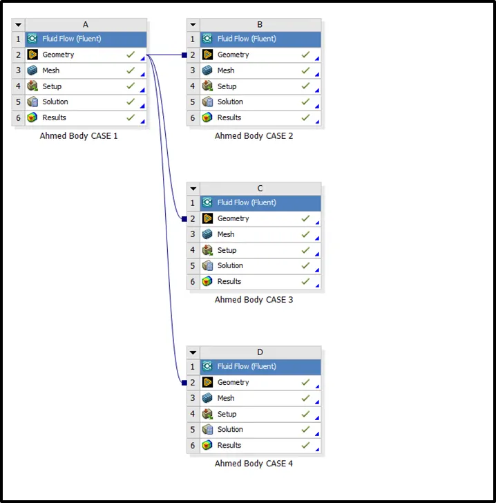
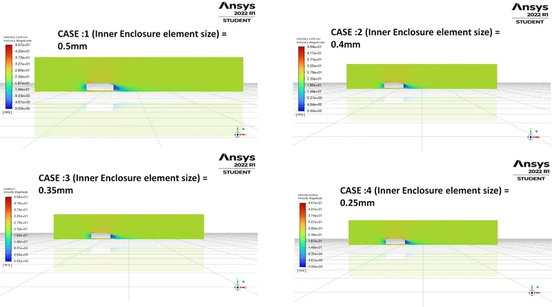
- Inner Enclosure element size = 50mm
- Inner Enclosure element size = 40mm
- Inner Enclosure element size = 35mm
- Inner Enclosure element size = 25mm
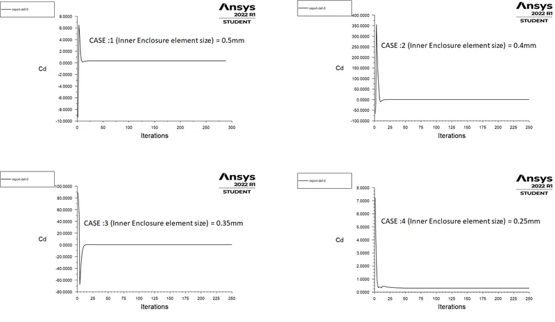
Drag Coefficient Comparision :
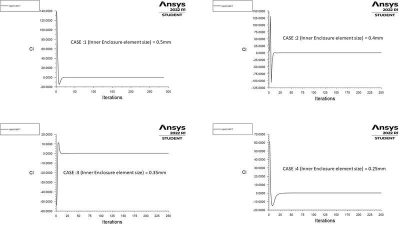
Lift Coefficient Comparision :
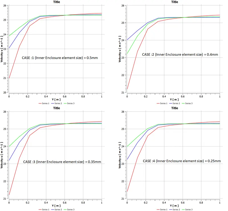
Probe Velocity Comparison :
Go to Postprocessing > Insert Line > Give x,y,z co-ordinates > Go to Insert > Chart > Selct line 1 > Set x axis as y > y axis as velocity in u direction
Vertical Probes at x = 2m,2.5m & 3m to calculate Velocity in U vs Y
Velocity Contour Comparision :
Recirculation Region observed in Postprocessing using Velocity Vectors
Grid Independence Test :
|
Sl.No |
Cell Size (∆X) |
No of Cells |
Drag Co-efficient (C_d) |
Lift Co-efficient (C_l) |
|
1 |
0.5mm |
133457 |
0.33742863 |
0.23613167 |
|
2 |
0.4mm |
167447 |
0.32639352 |
0.23167236 |
|
3 |
0.35mm |
195341 |
0.31765882 |
0.23281339 |
|
4 |
0.25mm |
354992 |
0.30702844 |
0.23464362 |