Week 3 - External flow simulation over an Ahmed body.
AIM:
To study external aerodynamic simulation over an Ahmed body for a velocity of 25 m/s and to perform a mesh independence test with default air properties in fluent.
OBJECTIVE:
- To describe Ahmed's body and its importance.
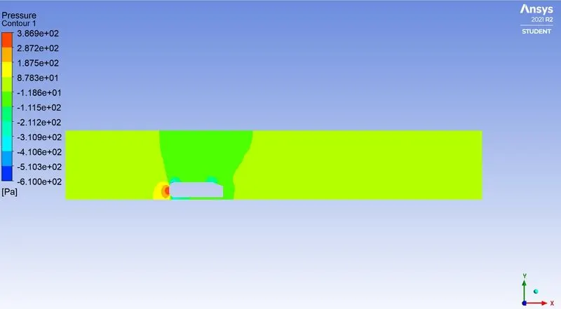
- To explain the reason for the negative pressure in the wake region.
- To explain the significance of the point of separation.
- To compare the cell count, average outlet temperature, and number of iterations tor convergence tor the given two case studies
- To perform mesh independent study for any one of the case studies,
- To use contour & line plots to study the output values of velocity and temperature along and across the length of the pipe
THEORETICAL EXPLANATIONS: -
AHMED BODY:
The Ahmed body is a generic car body (a simplified vehicle model). It is used in the automotive field to study the impact of the flow pattern on drag. The external flow around the vehicle is characterized by high turbulent and three-dimensional flow separations as well as there is a growing need for more insight into the physical features of these dynamical flows. Ahmed body is made up of around the front part, a moveable z slant plane in the rear of the body to study the detachment phenomena at different angles, and a rectangular box that links the front part and the rear slant plane. The principal objective to study such a simplified car body is to tackle the flow processes involved in drag production. Through perceiving the mechanisms involved in creating drag one can be able to design a car to minimize drag and therefore reduce fuel consumption and maximize vehicle performance.
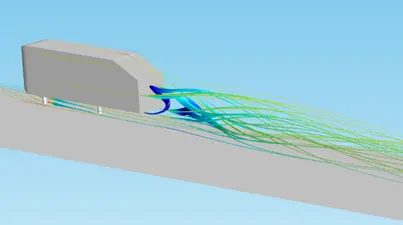
An Ahmed body represents a simplified vehicle volume which helps understand the fundamental physics, lift and drag forces and coefficients at certain velocities, pressure differences and analyzing the vortices, turbulence, and Reynolds number. Ahmed body CFD simulations can be used to validate numerical models with the available experimental data. Once the numerical model is validated, it is used to design new models of the car.
Its shape is simple enough to allow for accurate flow simulation but retains some important practical features relevant to automobile bodies. This model describes how to calculate the turbulent flow field around a simple car-like geometry using the Turbulent Flow, k-epsilon, and k-omega interface.
SIGNIFICANCE OF AHMED BODY:
- Ahmed Body plays a vital role in testing the aerodynamic properties of vehicles.
- It is also used to describe the turbulent flow field around a car-like geometry and later to design new car models with validated results.
WAKE REGION:
The region of recirculating flow or disturbed flow behind a moving or stationary blunt body, caused by viscosity, which may be accompanied by flow separation and turbulence. The wake was shown to be highly dependent on slant angle. For slant angles less than 12°, the flow remains attached over the slant. The flow is essentially two-dimensional and has low drag. Between 12° and 30°, the flow becomes much more three-dimensional as the c-pillar vortices form. These reach maximum strength at 30°. The drag increases significantly as the low-pressure cores act on the rear surfaces. Past 30° the flow separates fully off the slant. This results in a sudden decrease in drag and weaker c-pillar vortices.
REASON FOR NEGATIVE PRESSURE IN THE WAKE REGION:
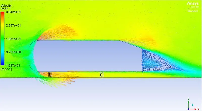
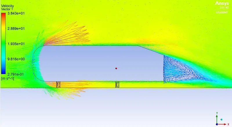
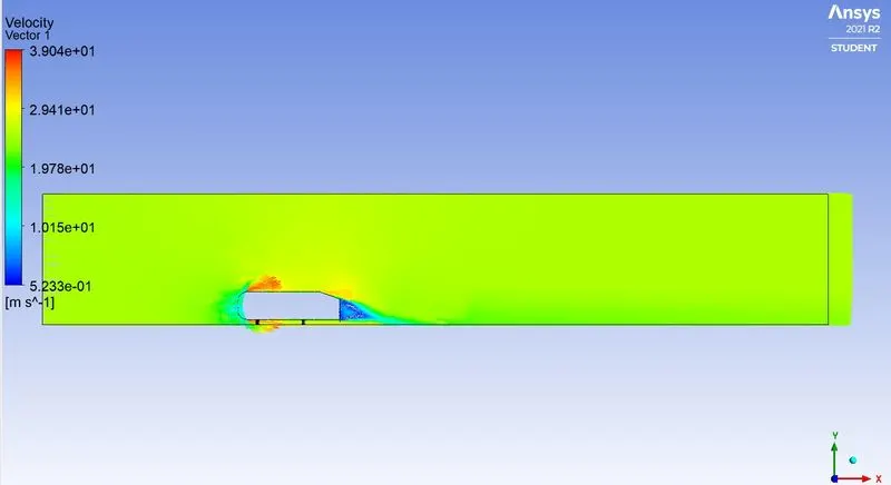
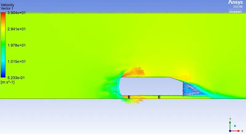
The path lines show the exact circular motion or vorticity generation just at the rear end of the car. The separation takes two regions of distribution. One at the upper part of the rear and the other at the lower part of the rear end.
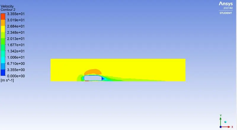
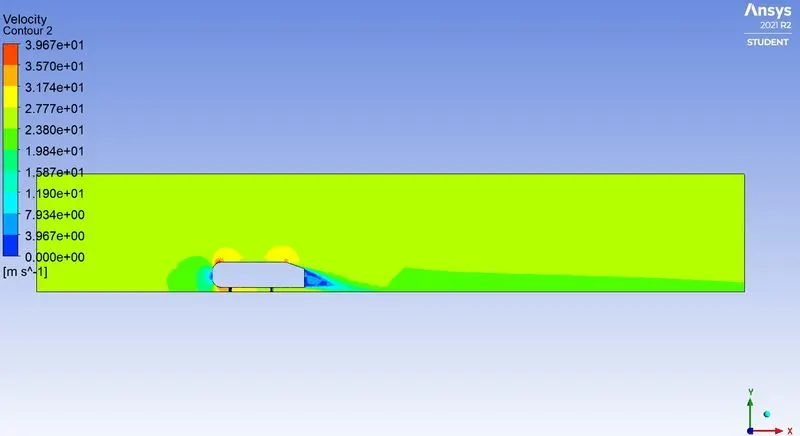
The path lines show the nature of the fluid interaction with the rear end of the Ahmed body which here shows that the fluid just after leaving the contact from the slope still possess the momentum in it and the fluid particles near to the surface almost show the no-slip region which means the very least possible velocity of the fluid particles is in contact with the slope and base of the rear part. Thus the fluid particles away from the rear region having the higher pressure beside the wake region try to approach from the higher pressure region to the lower pressure region thus creating a circularity exactly in the wake region created.
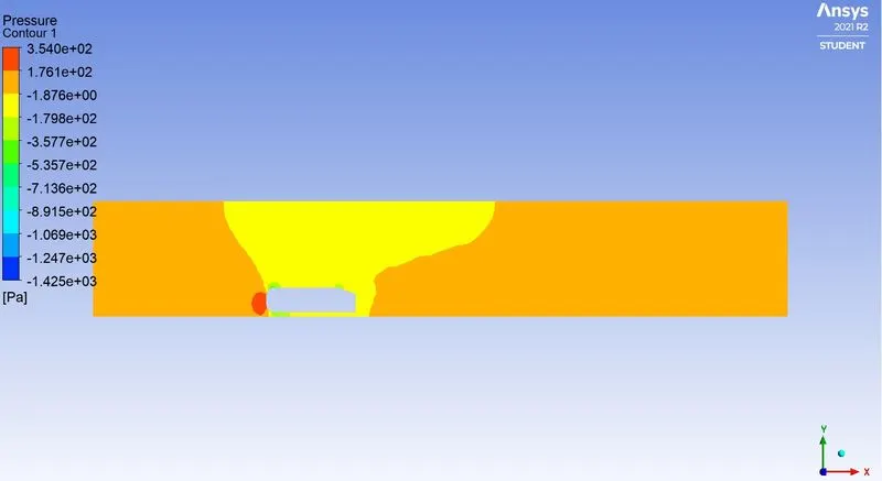
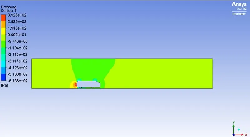
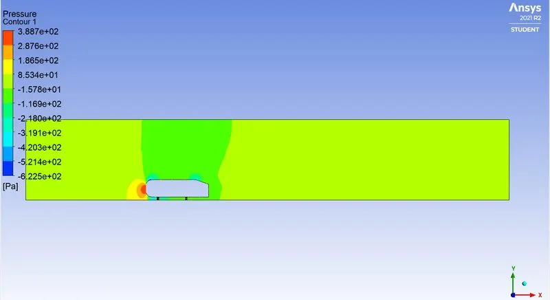
The body penetrating the fluid creates a region of emptiness just beside its end due to the nature of the geometry of the body here, which can be seen least in the case of a perfectly streamlined-shaped body. This emptiness created is a low-pressure region where atmospheric pressure tries to fill the space, thus dragging the fluid column with it. which creates the region of vorticity. This also results in the huge pressure gradient in the region exactly rear of the body creating the negative pressure at the end. This is the layman’s reason why there is negative gauge pressure in the wake region.
SIGNIFICANCE OF THE POINT OF SEPARATION:
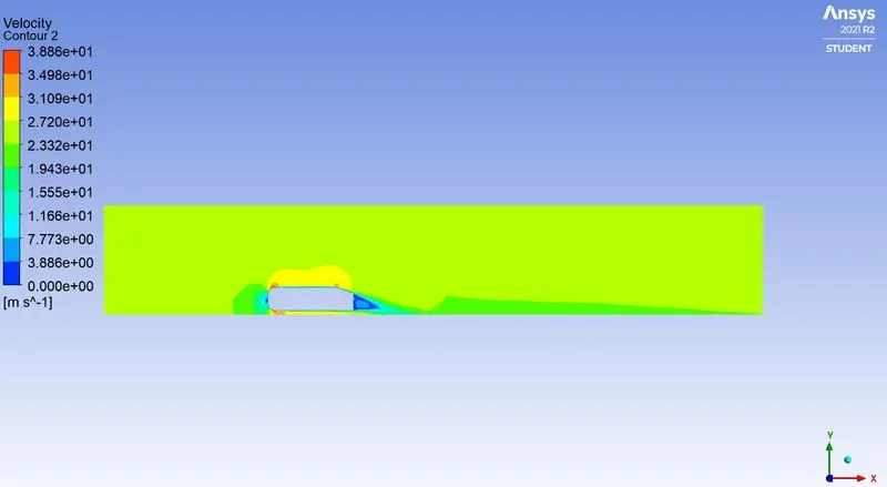
The fluid separation point can be defined as a point where the dv/dy i.e., the gradient of velocity goes zero along with the dp/dx = 0, for the specific point. In a more simplified term, we can say that at the point where the velocity gradient goes zero and the pressure gradient along the x-direction goes zero the point of separations starts occurring or the negative pressure gradient starts forming after that point. The point of separation cannot be understood just by a single contour in a hard and fast way. It can be supportively studied with the help of the dp/dx plots or velocity plots w.r.t the Y direction and other such plots in which we can see the nature of such physical properties like dp/dx=0, and dv/dy=0 experiencing in a particular region of fluid and body interaction.
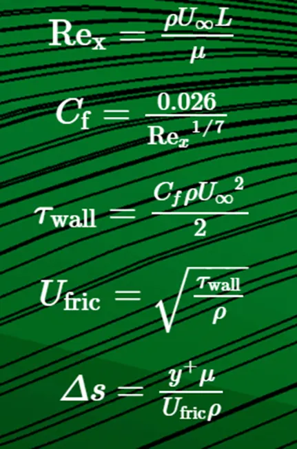
TO CALCULATE `Delta`S FOR Y+ VALUES(50,100,150).
This is the link to calculate the `Delta`s value:-https://www.pointwise.com/yplus/index.html
PROCEDURE: -
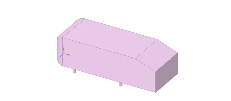
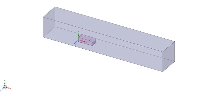
*The geometry is imported by the drag and drop method and the dimensions are checked in the space claim.
*The enclosures are been created around the Ahmed body is converted into a Volume around the geometry.
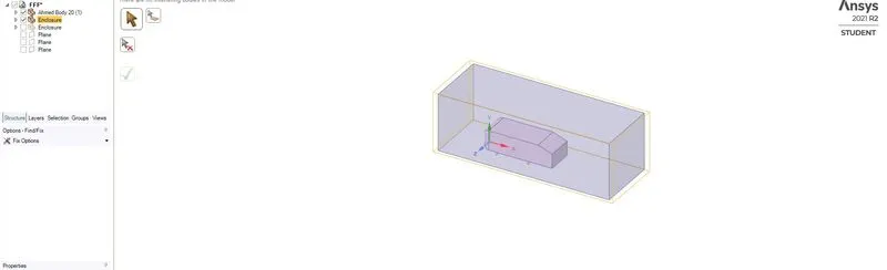
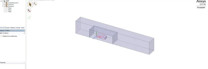
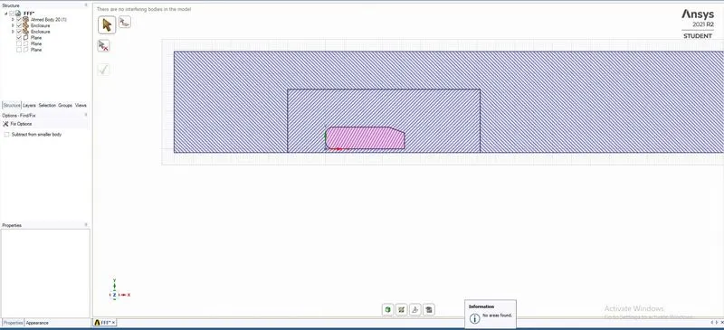
*The enclosures are checked for intersection and fixed for better meshing. The enclosures are been checked share so mesh inflation can be done to interconnect the volumes.
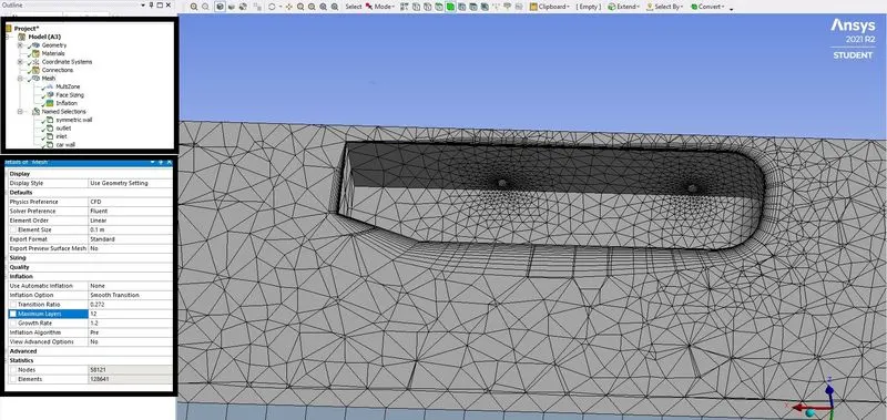
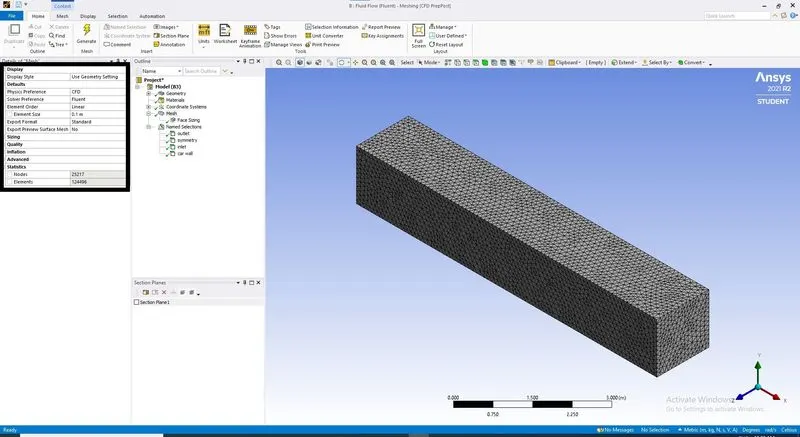
*The mesh is created for an element size of 0.1m and the quality of the elements we more than 40%, Mesh methods were used to creating multizone elements, and Inflation was added Y+ terms of 50,100 and 150 for the mesh by 6 layers near the Ahmed body region. The mesh generated was an obsolete mesh and Names were assigned for the car wall, symmetry, and the inlet, outlet.
*The Setup workbench is started and given recommended parameters.
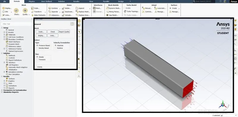
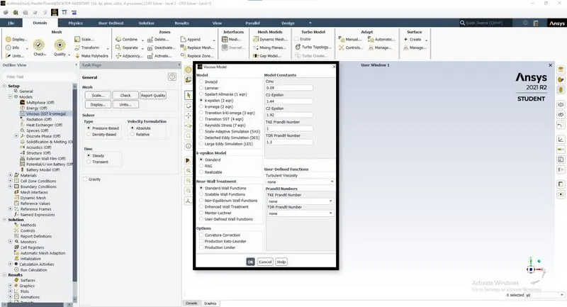
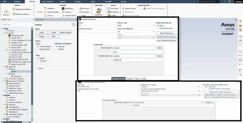
*The model was turned on for turbulent flow model, The material is been added, the air is been initiated with specific values at both the inlets.
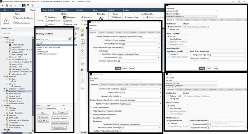
*Boundary Conditions are applied on the inlet with velocity values of 25m/s, outlet with pressure at zero, and the wall with No-slip conditions.
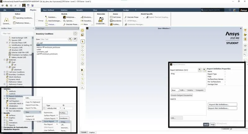
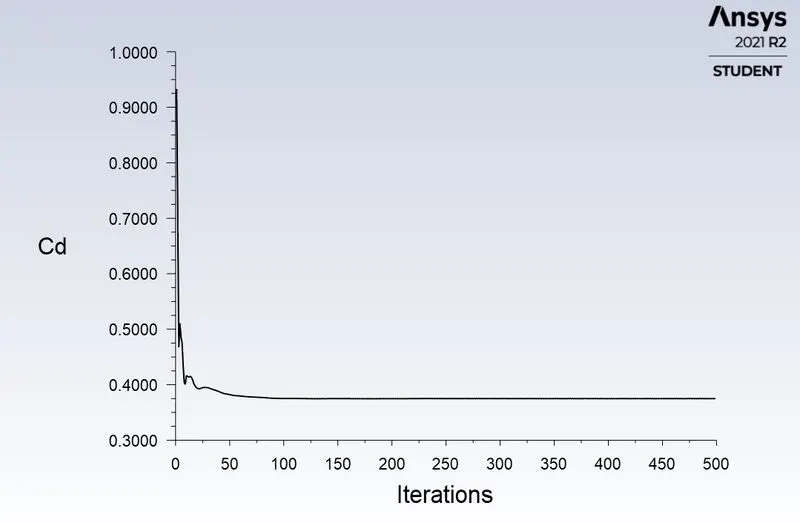
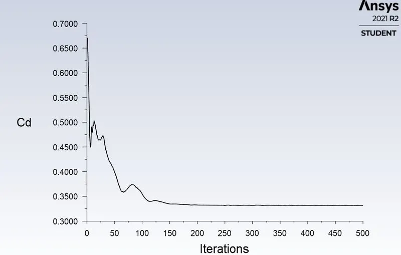
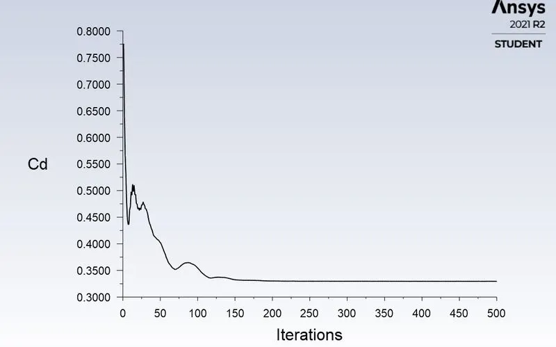
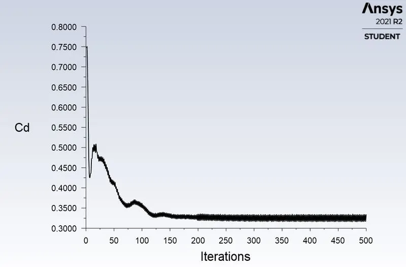
*Report definition is done by creating a report for the Coefficient of drag.
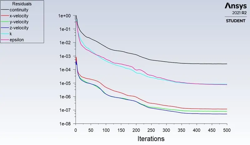
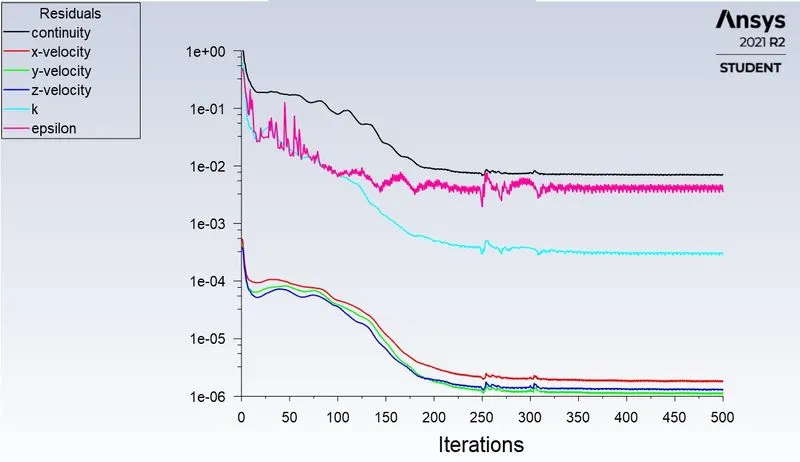
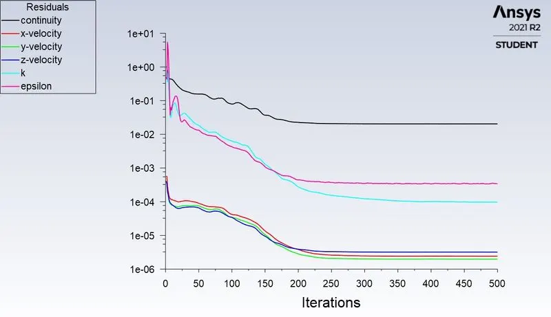
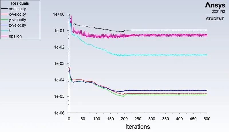
*Solution method is selected for SIMPLE method and the residuals are unselected for check convergence.
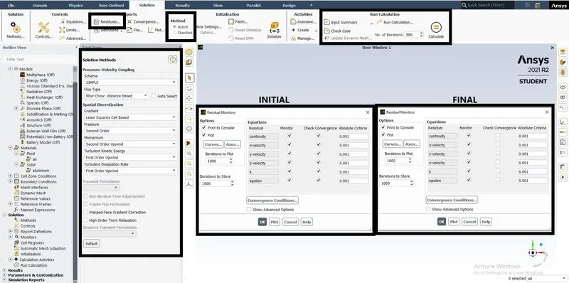
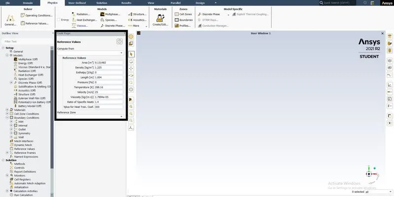
*Reference value is checked for the area, length, and velocity parameter and their values.
CASE 1
*Reference value is checked for the area, length, and velocity parameter and their values for Course mesh without any multiple enclosures
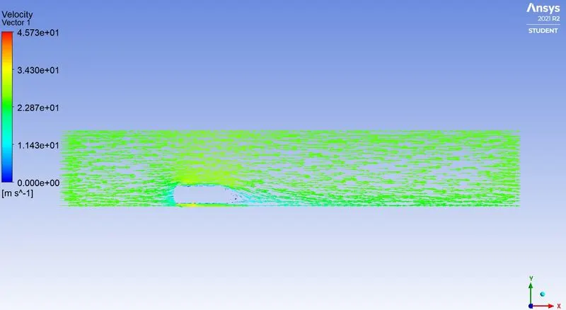
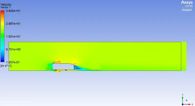
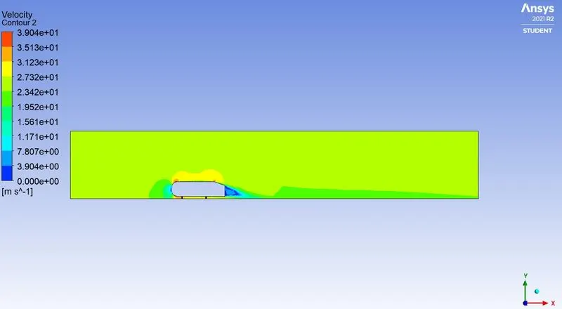
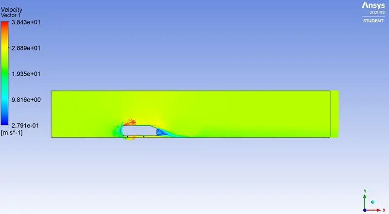
*The Coefficient of drag and velocity vector are plotted to show the model has reached convergence and contours for pressure and velocity.
CASE 2
*Reference value is checked for the area, length, and velocity parameter and their values for Y+=150.
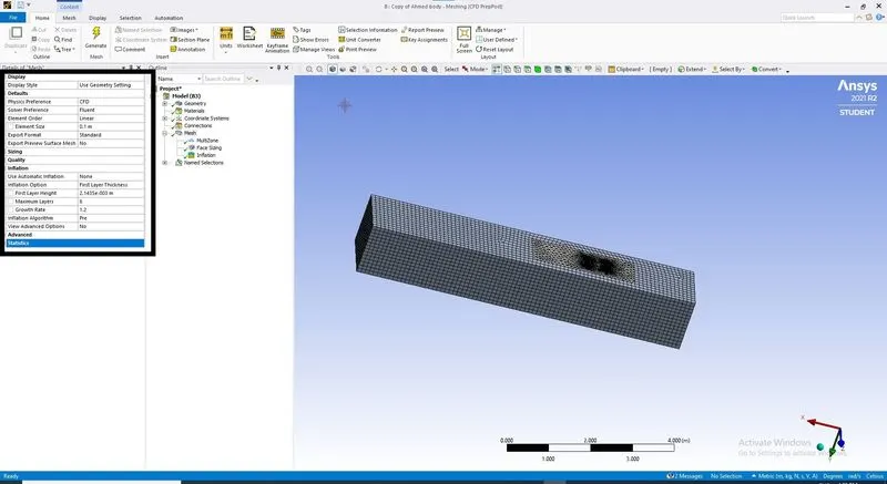
*The Coefficient of drag and velocity vector are plotted to show the model has reached convergence and contours for pressure and velocity.
CASE 3
*Reference value is checked for the area, length, and velocity parameter, and their values for Y+=100.
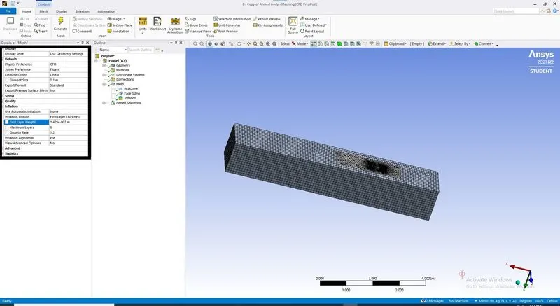
*The Coefficient of drag and velocity vector are plotted to show the model has reached convergence and contours for pressure and velocity.
CASE 4
*Reference value is checked for the area, length, and velocity parameter and their values for Y+=50.
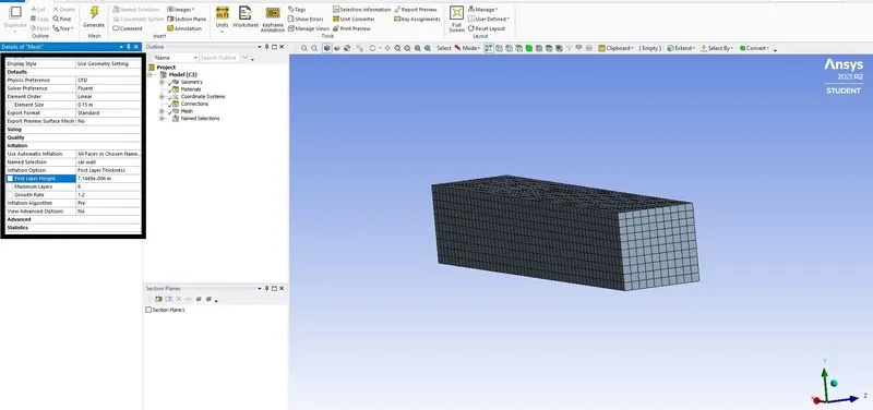
*The Coefficient of drag and velocity vector are plotted to show the model has reached convergence and contours for pressure and velocity.
RESULT:-
|
MESH GRID INDEPENDENCE |
NUMBER OF ELEMENTS |
COEFFICIENT OF DRAG |
% OF ERROR OF STANDARD (0.33) |
|
SETUP CASE |
124497 |
0.3748 |
13.57% |
|
Y+= 50 |
319925 |
0.334 |
1.21% |
|
Y+= 100 |
293474 |
0.32993 |
0.0212% |
|
Y+= 150 |
275710 |
0.33151 |
0.45% |
CONCLUSION: -
- When the geometry is symmetrical we can use its section symmetrical part, which can help us to the drastic reduction in mesh grid elements lead to minimizing computational time and power.
- Ahmed body can use as a dummy simulation to set the setup for other car bodies. By doing this, we can verify our results which got from rough simulation to validate our simulation setup for actual geometries.
- Generating mesh with the reference of Y+ value improves the accuracy of results at the surface when the flow is turbulent near the wall faces. It also affects the accuracy of drag and lifts coefficient values as this value we observe at the wall surface.
- The negative pressure around the body is generated due to the boundary layer separation which creates a high turbulent flow zone.
- The boundary separation and recirculating of the flow and also the effect of shear stress. To overcome the shear, stress pressure turns negative to balance the effect.
- A grid independence test is important to validate the generated mesh of the final setup.