Week 3 Challenge : CFD meshing on Turbocharger
CFD meshing on Turbocharger
Major steps for Volumetric Meshing
1. Surface cleanup (Filling Holes)
2. Surface cleanup (Deleting Interferring geometries)
3. Enclose geometry
4. Assigning and creating PIDs
5. Surface Meshing
6. Volumetric Meshing
1. Surface Cleanup (Filling Holes)
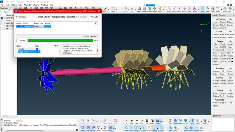
Checking for Single Cons in the Geometry
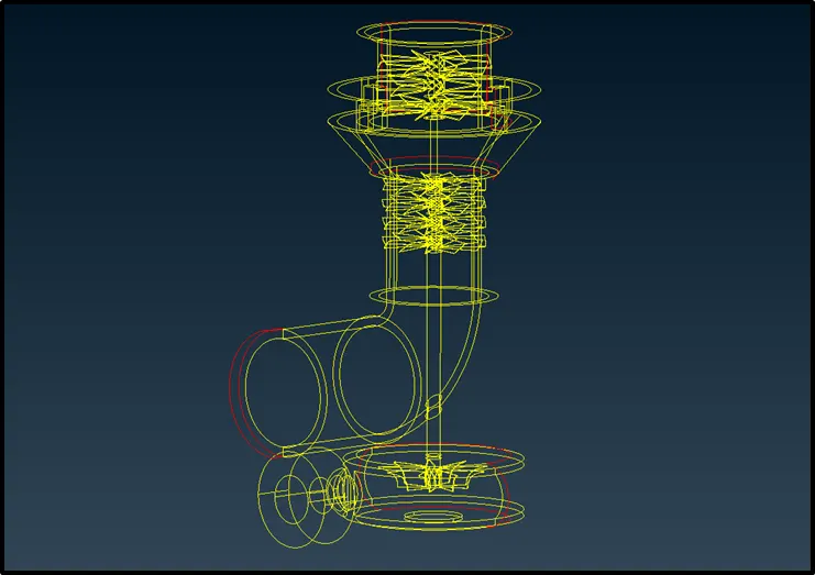
Resolving all Single Cons one by one
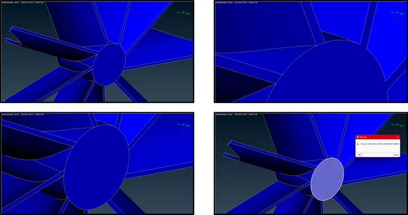
Deleting interferring geometries
Choose Delete > Left Click cross hatch (Pink section) > Middle Click > Yes

Filling Holes :
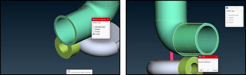
Identify unfilled surfaces.
Choose New > COONS > Go with either Loop or Entity mode of selection > Middle Click (Check Preview) > Ok (Accept Surface)
Similar action to be taken for all unfilled surfaces
Critical Treatment of surface filling for holes:
For single Cons of this Section, loop feature cannot be used to stitch the hole. This hole needs to constructed for using Loop feature.
Use Project option to project cons wherever necessary to connect Cons
Project > Select Hot Point > Select Con
Then use New to construct surface necessary
New > COONS > Preview > OK
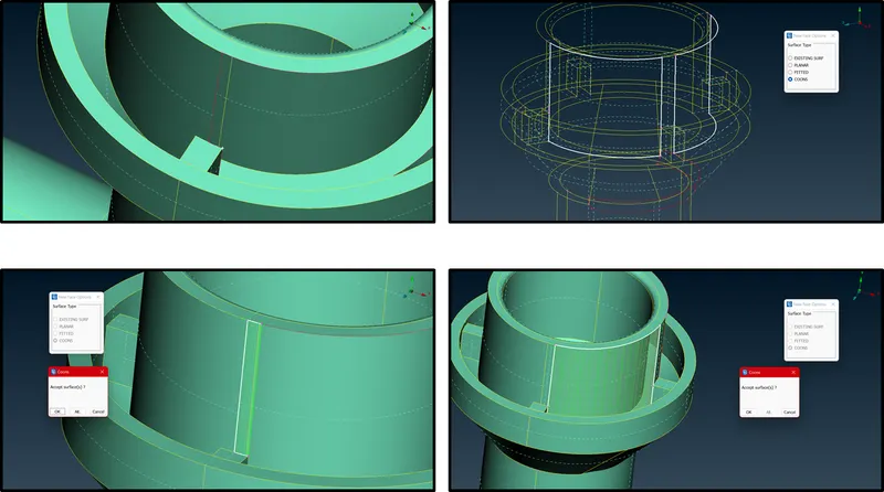
Critical Treatment of surface filling for holes with interferences in Geometry :
CASE I :
For Interferring Surfaces with no contact and no formation of CON, one needs to create a Con so as to delete interferring surfaces.
Intersect > Select first surface (Middle Click ) > Middle Click for choosing second surface > Choose second surface > Middle click for output
Now delete the extra surfaces permanetly using Delete.
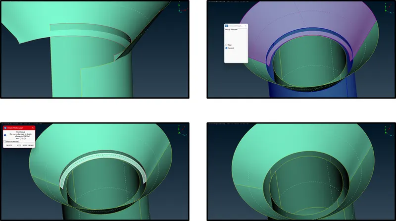
CASE II :
In this case, one needs to sepeartely construct cons using Parametric option.
Parametric > Input 0.5 (u-par)> Iterate for constructing many uniform points (Symmetric) along the single con
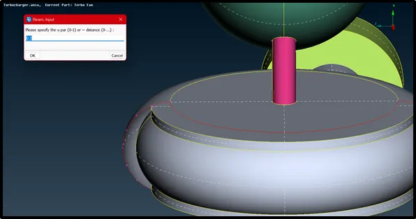
Now use
New > COONS > Entity mode of choosing CON > Select CONS > Preview by Middle click > OK
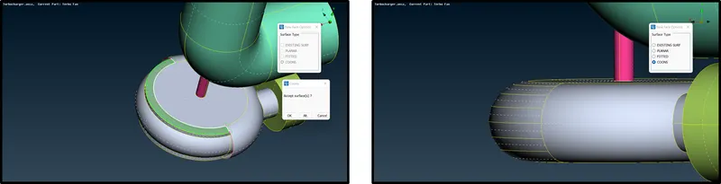
CASE III :
Deleting Extra surfaces, because we are trying to make the whole rotor assembly a single void surface from inside.
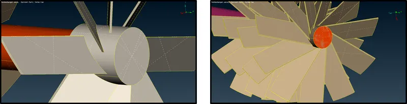
For interferring extra surfaces, one can clearly see mixing of colours of surfaces, which clearly shows interferring of surfaces.
Use Project (CONS) to create new surface con to seperate, the brown element from Pink Element
After projecting, Fine the resolution of the projection. Now the pink element is seperated from Brown Impeller element. One can clearly delete the mixed surface which deletes the mixing of surfaces.
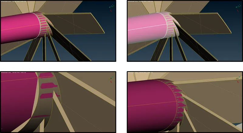
Similarly for deleting the face of the Impeller, the cross hatch was symmetric since it shared the crois hatch with the whole body of the impeller.
Hence used Cut option to create surfaces to seperate the circular section with the body.
Then Delete the surface
Later checking for Geometric Single CONs
3. Enclose Geometry
Enclosing the geometry for CFD (Volumetric Mesh) and assigning the right PIDs
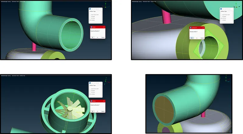
Creating new surfaces using New command
New (Faces) > COONS > Loop > Select the unfilled CON > If surface accepted then OK; if not check ALT and then OK
Surface Gaps to be checked and filled to make the Volume leak proof for Volumetric Analysis
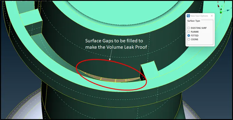
Again use the same appproach using New from Faces but this time using Fitted option for creating new surface
New (Faces) > Fitted > Loop > Select the unfilled CON > If surface accepted then OK; if not check ALT and then OK
4. Assigning and creating PIDs
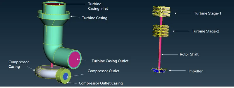
Understanding the whole assembly components and renaming the components
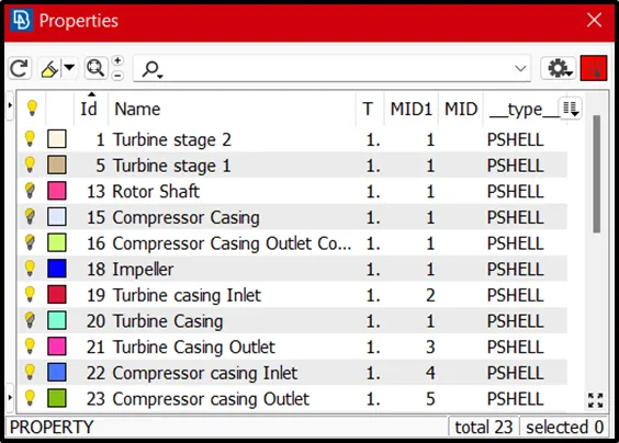
Properties > Double Name of the Component for editing the name > Re-enter edited name > Ok
or
Properties > Right Click > New > Pshell > Pshell > Enter the name > OK
5. Surface Meshing
Surface Meshing of the Components are done part by part. The below details are given for Target lengths to be applied in order to capture the objects correctly
- Blade stage-1 = 1 mm
- Blade stage-2 = 1 mm
- Impeller = 2 mm
- Shaft rotor = 1 mm
- Turbo casing = 5 mm
- Compressor casing = 5 mm
- Inlet casing cover = 5 mm
Starting from Large target length meshing i.e Turbine Casing, Impeller Casing and its Inlet and Outlet ports
Procedures to be followed for 5mm Meshing
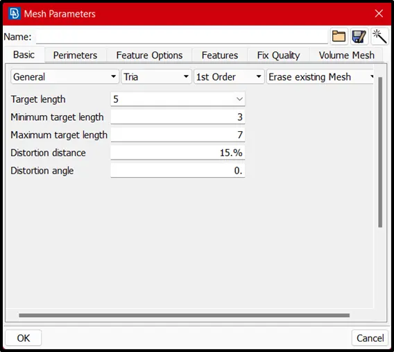
1. Go to Mesh Parameters > Set Mesh shape as Tria > Set Mesh Target length = 5mm > Set Min. Target Length = 3mm > Max. Target Length = 7mm
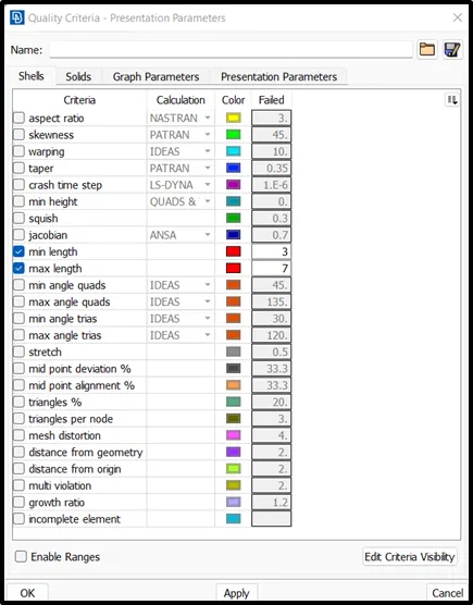
2. Go to Quality Criteria > Set Min. Target Length = 3mm > Max. Target Length = 7mm
3. Go to Mesh Buttons > Length > Parameters > Select the whole body > Enter 5mm target length > Macros > Select the whole body > Enter 5mm target length
4. Spot Mesh > Visible
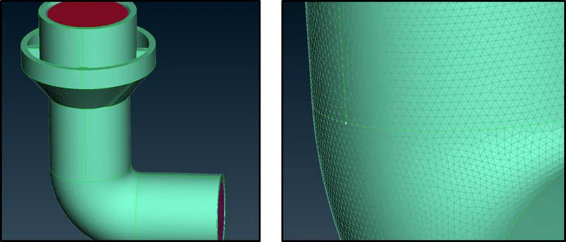
Note : Look for interfering surfaces and make sure that un-required surfaces are deleted using Delete.
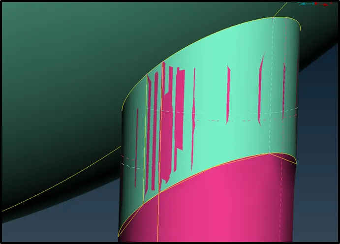
Meshing Challenges for Rotor Shaft :
Since meshing target lengths for Impeller and rotor shaft are different, question occurs at bringing uniformity of meshing target length at the edge of impeller and rotor shaft.
One has to carefully check for gradients in meshing target lengths, since macros has to be handled with care. Macros can vary from 1 to 2mm. Hence macros for either shaft or Impeller has to vary from 1 to 2mm
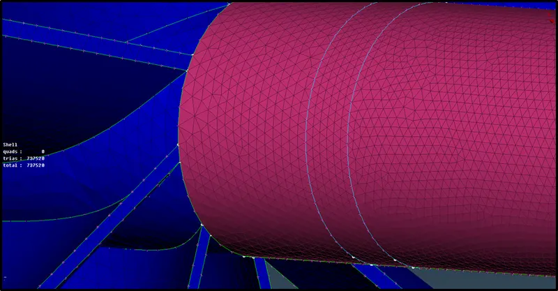
Meshing Challenges for Turbine Casing and Rotor Shaft :
Similarly, using the above approach, care has to taken care for keeping macros varying from 1 mm to 5 mm
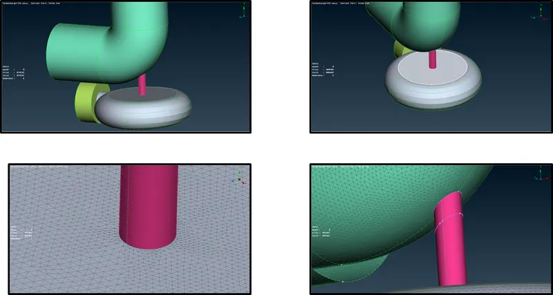
Complete Surface meshing is done now for whole assembly
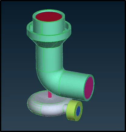
6. Volmetric Meshing
After surface meshing, one can click Volume mesh button.
Go to Volumes > Define > Work on > Whole DATABASE (db) > Ok
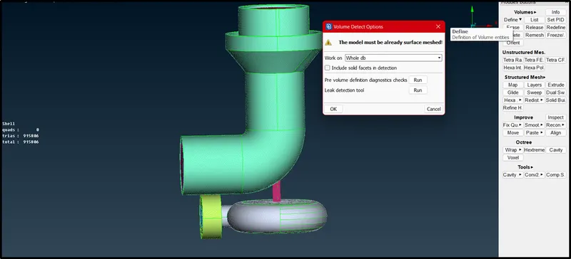
After defining volume mesh for the assembly, volumes are detected by the Define button. Now one has to select the required volume other than assembly thickness for meshing the fluid flow areas onlywhich is required for further CFD Analysis.
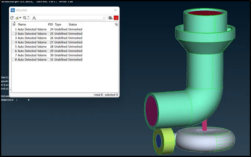
Carefully choose volumes which enlose the volumes for fluid flow. Delete the volumes that involve thickness of the components.
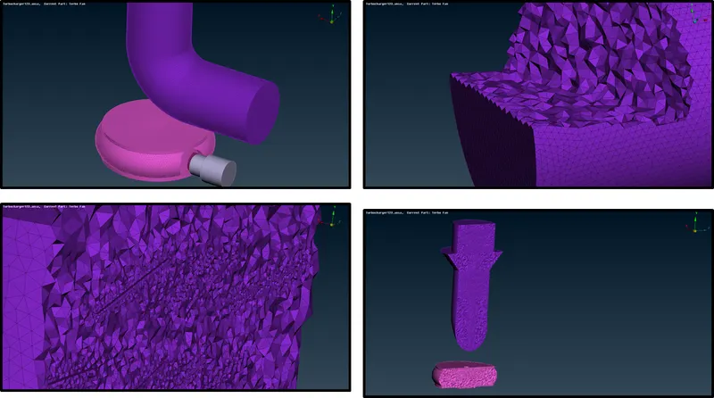
Now Right Click > Remesh > Tetra CFD (CFD Application Meshing)
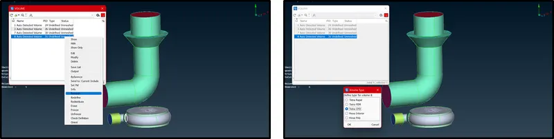
Similarly, this process must be done for all necessary volumes of the components of the assembly
Result :
Google drive link for Meshing File :
https://drive.google.com/file/d/1aJuW1v6VadLgqaNnn8A1kW-RDDDrYoqq/view?usp=sharing