Week 3 - 2D meshing for sheet metal
2d meshing of sheet metal(hood component)
aim: pre-processing of hood automotive components for crash analysis.
given hood components:
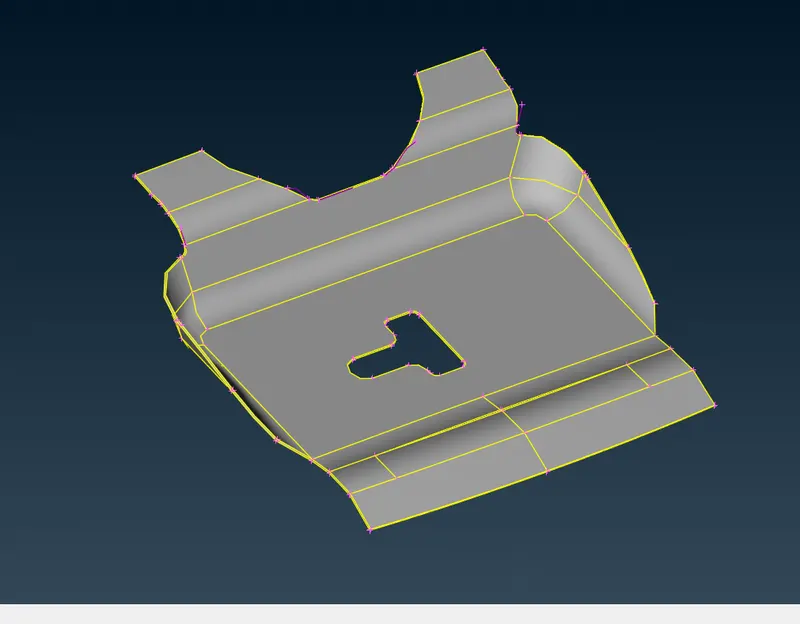
fig 1: flange
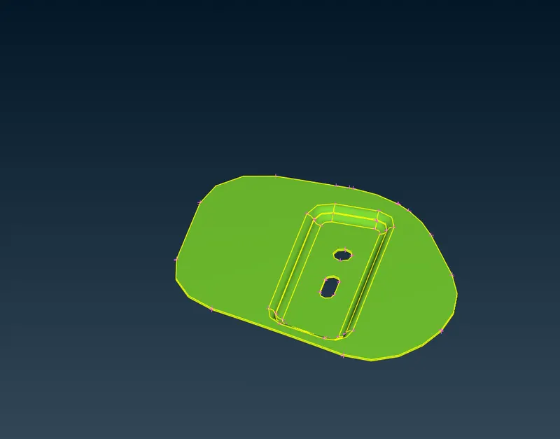
fig 2:-finge
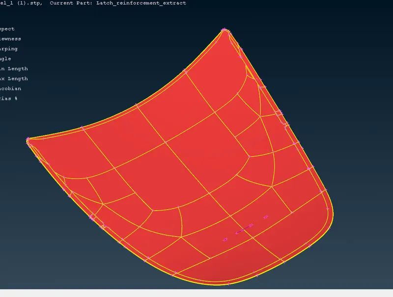
fig3:-outer panel
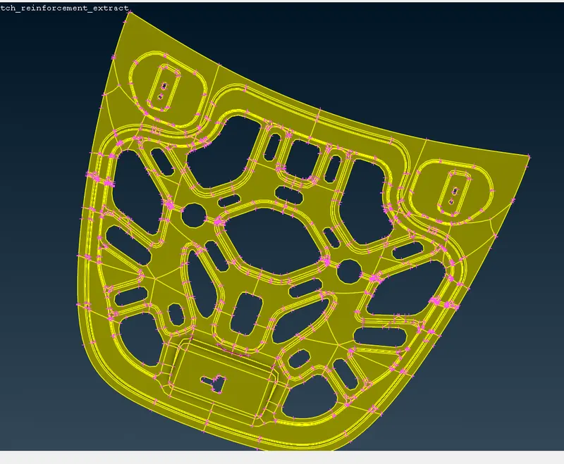
fig 4 :- inner panel
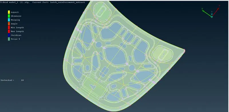
fig 5: overall components
introduction:-
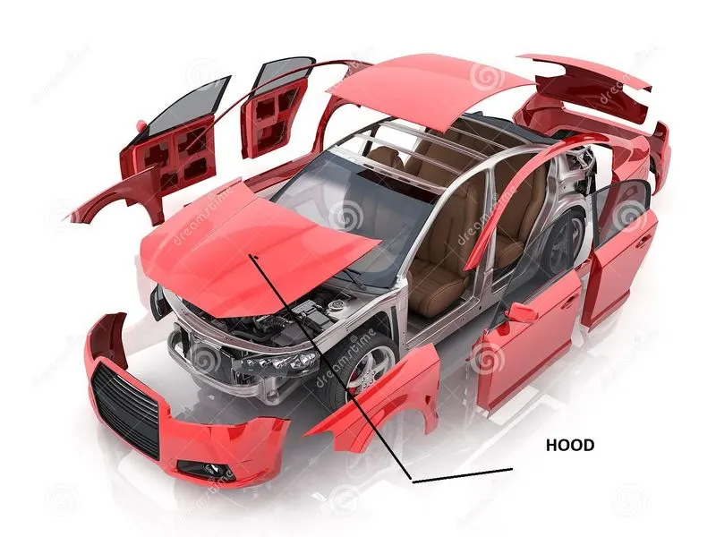
fig 6
as shown above, the hood component is a cover for the engines, so they are exposed to heat from engines and protect engine equipment from accidents. Most car companies use sheet metal components with thicknesses of less than 5~6mm for hood manufacturing.
preprocessing of hood components in this project is carried out based on crash analysis.
this is done in 4 stages
- geometric cleanup
- mid-surface extraction and geometric clean-up on the mid-surface
- meshing based on quality criteria.
- thickness assigning
- importing the geometry
go to files-open-choose the drive location -then choose the supporting that need to open.
ansa support for .stp, .igs, solid works files(.sldpart, .sldams), .part(Unigraphics), all CATIA files(ex:- .CATpart, .CATproduct etc).and lot more.
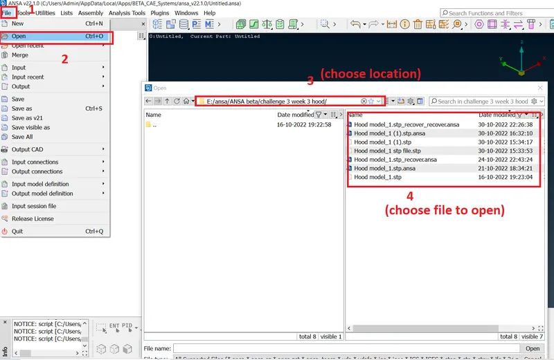
fig 7
- geometric set up:-
geometry imported as looked below,
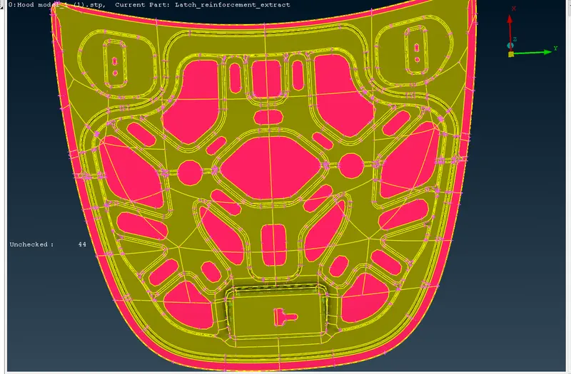
fig 8
the components representing different colours are stored in different PIDs this can be visualized in PID mode.
- after importing the geometry check for the geometrical errors by checks option.
- in this project, I have different components there fore highlight them one by one and perform preprocessing on them.
- we can hide and show the components by selecting the icons as shown below.
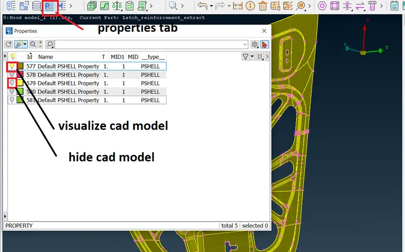
fig 9
- we can store the view so that boolean operations apply to the particular cad model only. this can be done by using a lock and storing it.
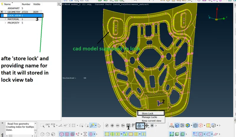
fig 10
- then set the length between hot points so that we can visualise the features more accurately
- change to mesh module tab-perimeters-length-choose perimeter option-select the surfaces-ok(middle mouse button)-set parameters value to 1 and set the macro value to 1-ok(middle mouse button).
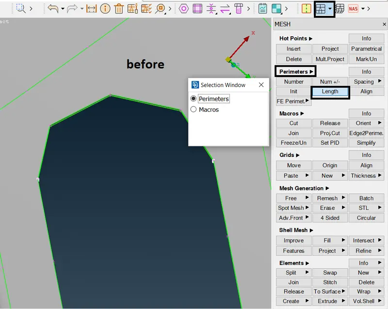
before setting the values to 1
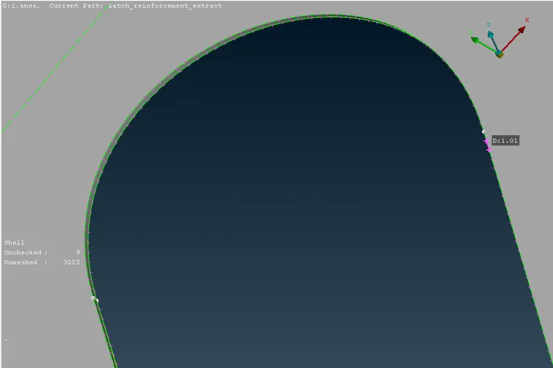
after setting the values to 1
- these settings need to be repeated according to the average element size before going to mesh the component uniformly.
- the setting of geometry is completed.
1. geometry cleanup:-
- after importing geometry into any preprocessing software it requires to do geometry check to identify the geometrical distortions and feature damages by deleting the surfaces etc., this are can be checked by the checks option in ansa.
- steps to follow
- tools tab-checks-geometry check(as we are interested in checking geometry)-(a window will pop up after step 3)execute after step 4 automatic geometric check is done and algorithm throughs errors detected by it as shown in fig 12
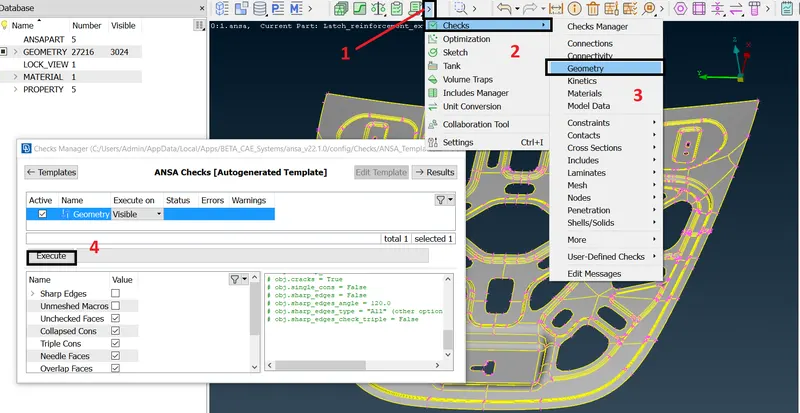
fig 11
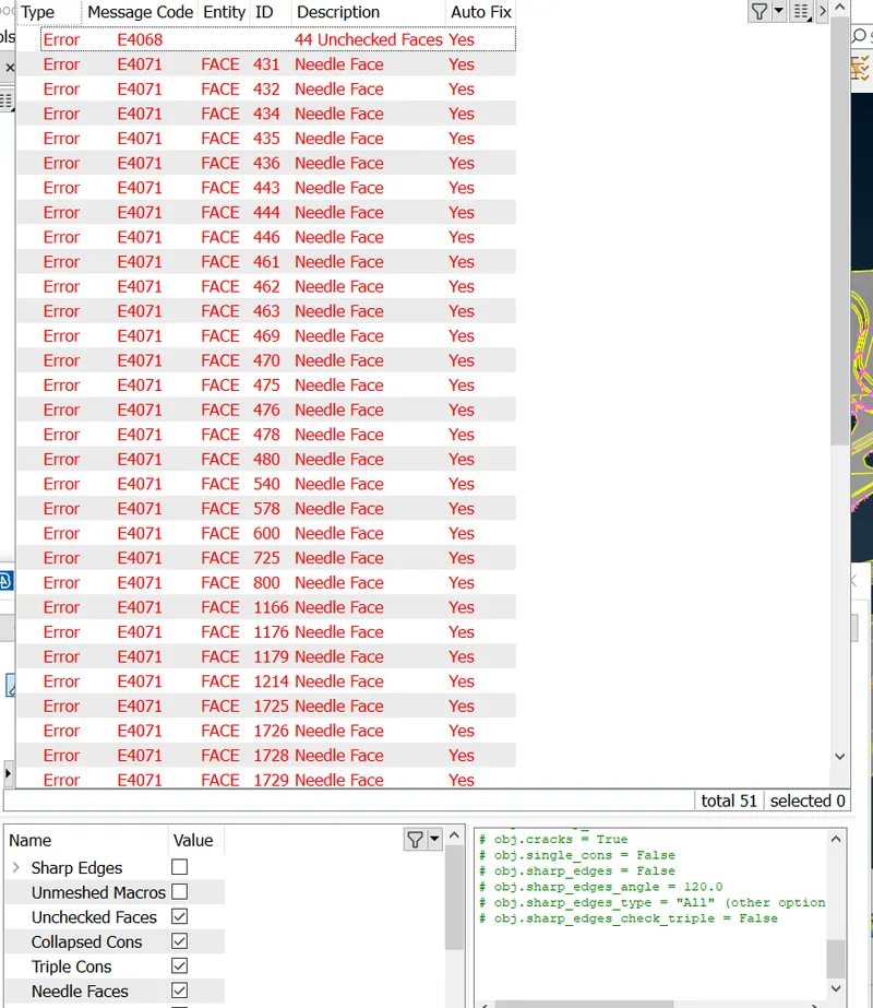
fig 12
we can highlight each errored area and visualise it separately from show only option and can work on it.
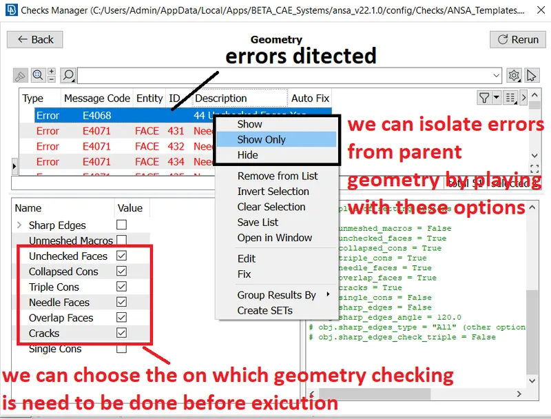
fig 13
these geometrical errors can be cleared in two ways
- automatically fixing the errors and
- manual fixing
automatic fixing:-
the following figure represents the same
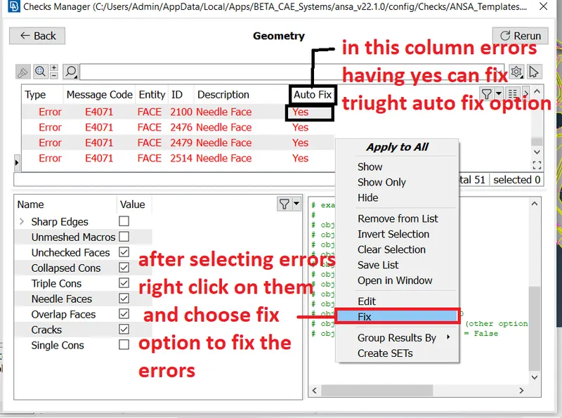
fig 14
- manual fixing the errors:-
needle faces can be cleared by toggling one of the cons and also by deleting the needle faces. having these needle edges leaders to create trias and also causes failed elements of minimum tria angles.
- for toggling
in topo module-faces-cut-right click on the corn to toggle
- for deleting the needle faces
topo module-faces-delete-select the surface to delete -ok
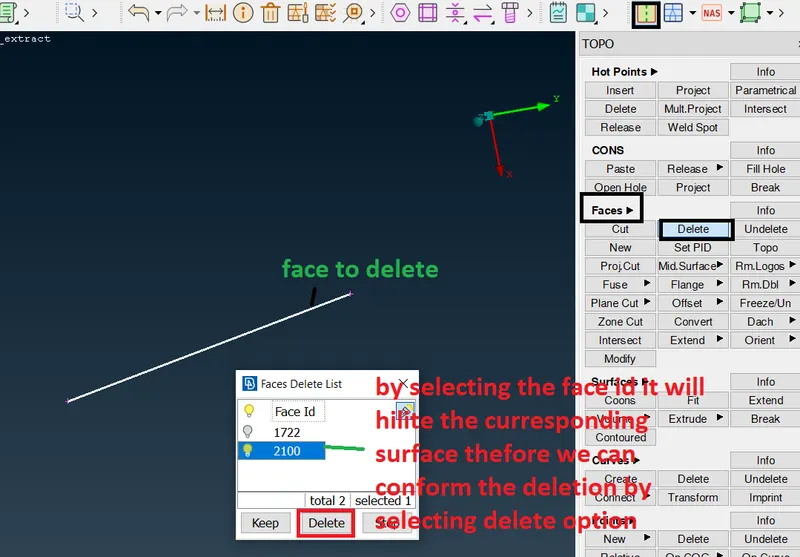
fig 15
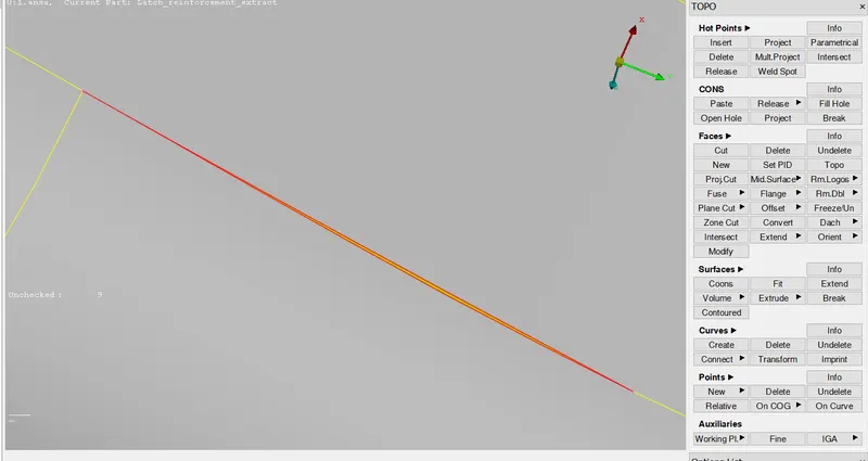
fig 16 after deleting the surface
above the figure, we can connect the cons by topo options.
topo module-faces-topo-select the cons to connect-ok(middle mouse click)
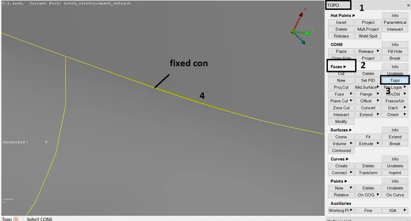
fig 17
- remaining errors can be cleared in the same way as mentioned above.
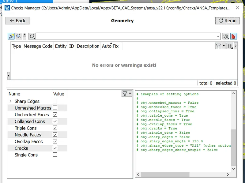
fig 18 surface with no errors
2. mid surface creation:-
- before creating midd surface check for the thickness of the component at a different location to check the uniformity of thickness over the component.
- the components in this project are having a uniform thickness and also having a thickness less than 5~6mm.
- the inner trim has a thickness of 0.75.
- the outer panel is 0.75 mm thicker.
- hinge parts have 1.20mm of thickness.
- the flange also has 1.20mm of thickness.
extraction of midd surface for inner surface:-
this can be done in two ways
- automatic
- manual
automatic extraction of mid surface:-
points to remember using this process are
- make sure all geometric checks are clear
- and check off the deleting original surface while creating midd surfaces option box.
- set property to auto-create.
- check on the 'apply thickness' to apply it automatically while creating midd surface itself
topo tab-faces-mid surface(for auto creation of surfaces)-choose the skin option (for PIDs with uniform thickness)-select the surfaces.
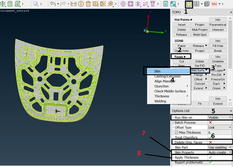
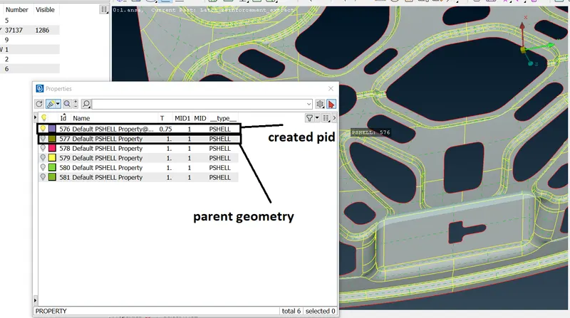
by following the above steps we can create midd surface as a separate PID with thickness assigned automatically without deleting the parent surface.
- the manual mid-surface
can be done by offset option
topo module-faces-offset-select surface -ok-according to the direction of vector shown enter the half of thickness value in such a way that surfaces created will appear in middle-ok(middle mouse button)-select no for deleting parent surfaces-ok
check for the surface errors
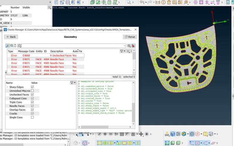
errors are cleared as shown below
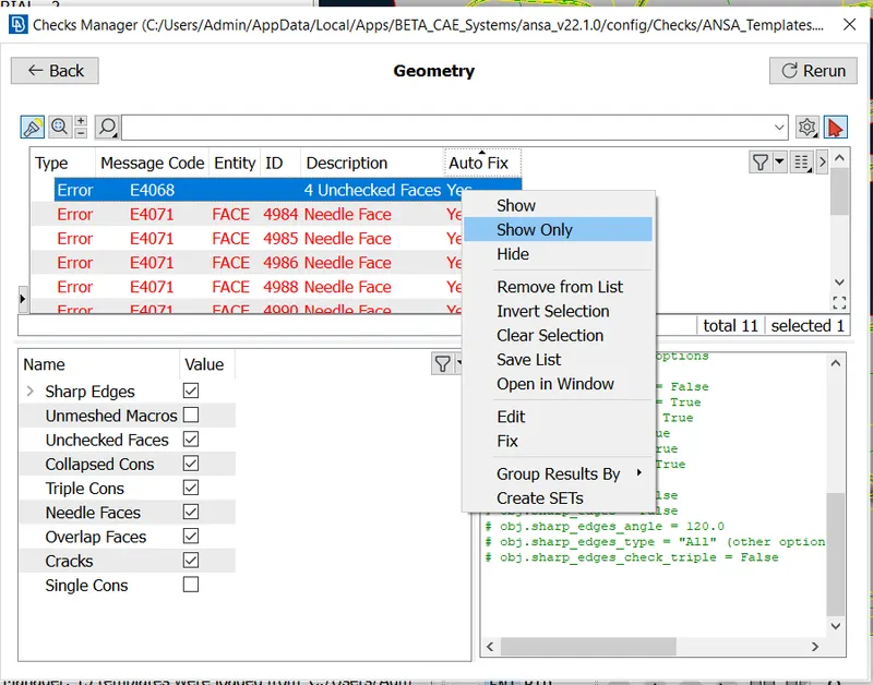
errors are highlighted as shown below
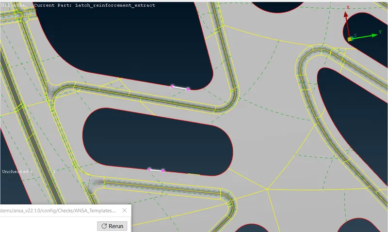
by selecting the show only option errors can be isolated by using neighbour's first level we can visualise the nearby surfaces as shown below.
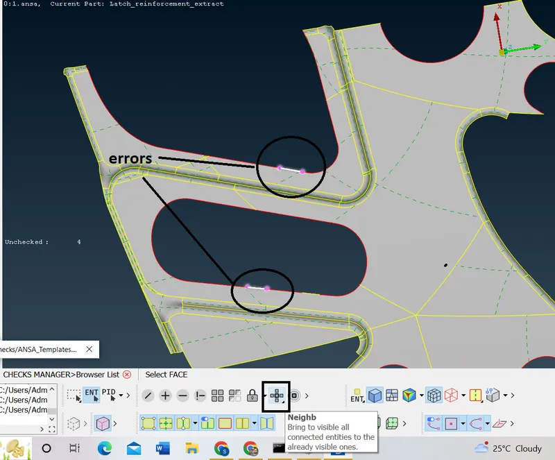
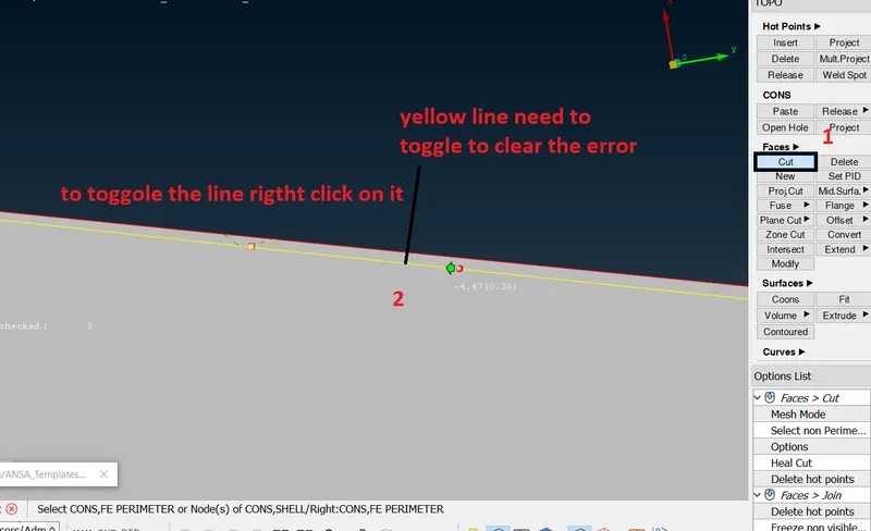
then by using the delete and cut options, we can clear the errors.
topo module-faces-cut -to toggle the cons by right-clicking on it.
topo module-faces-delete-select the face to delete-ok.
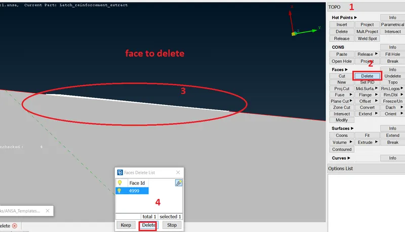
the same process can be followed to clear the errors.
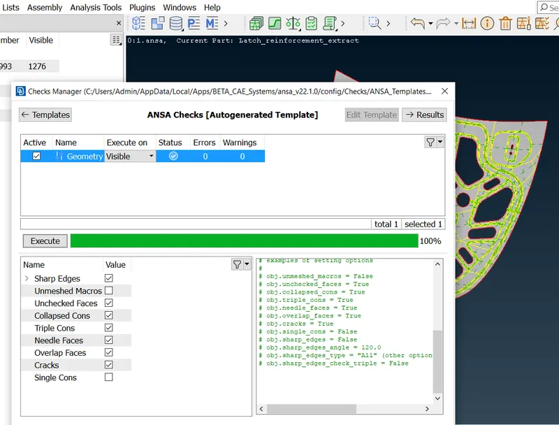
all errors are cleared.
- then go for toggling the unnecessary splits on the flat and curved surfaces and cutting the surfaces in definite shapes so that we can maintain the mesh flow properly.
- toggling and cutting the faces is done by cut option topo module(topo module-faces-cut)
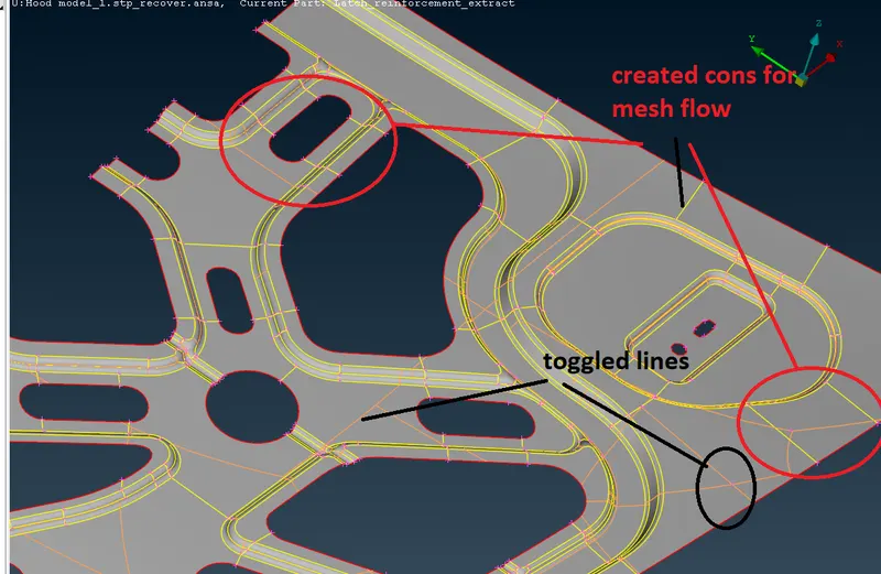
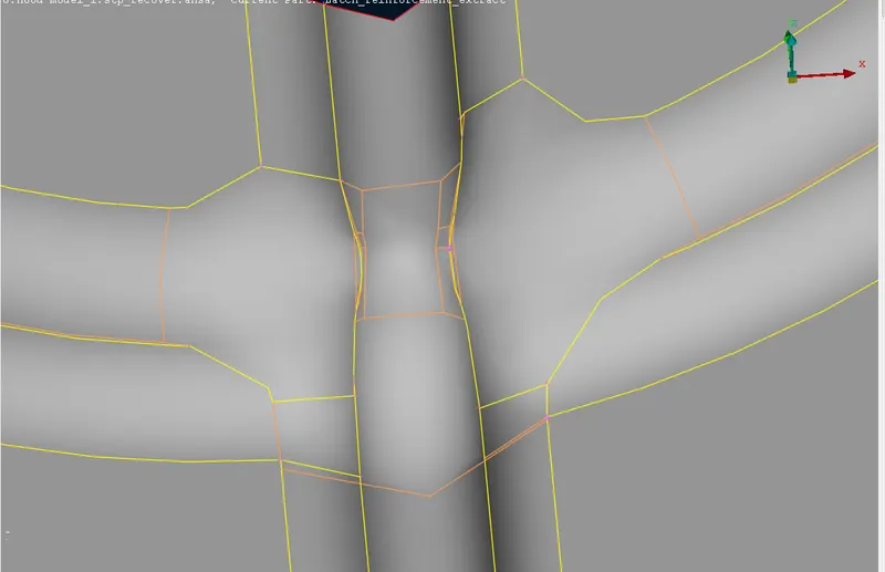
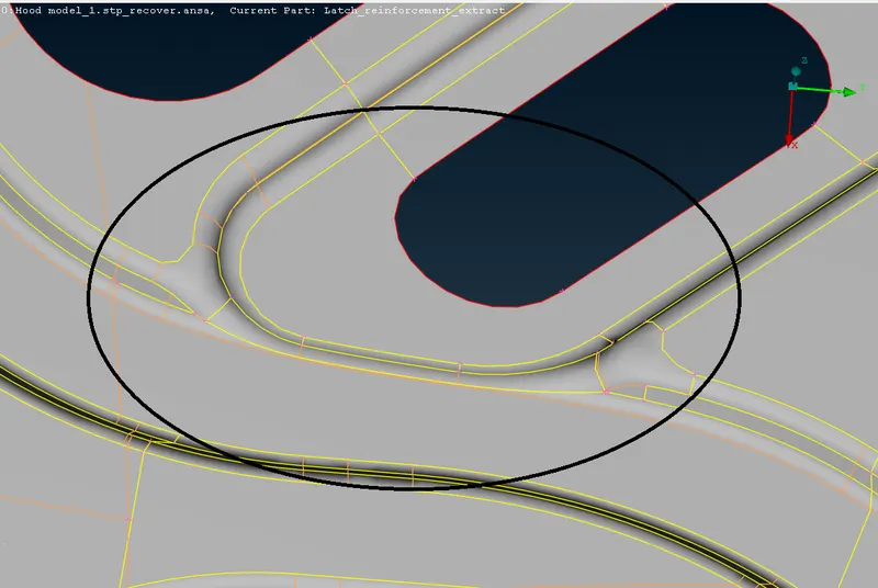
features shown above are captured in such a way that we can avoid element errors.
inner trim has symmetry about a centre axis. therefore meshing at one side and can reflect it (though symmetry option).
- meshing
- before meshing the surfaces set the perimeter values by using the length option to average the element length value.
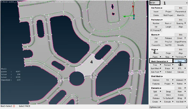
- 'best mesh' option is used to create the mesh
- mesh module-mesh generation-best mesh -select the surface-ok(mouse middle button)
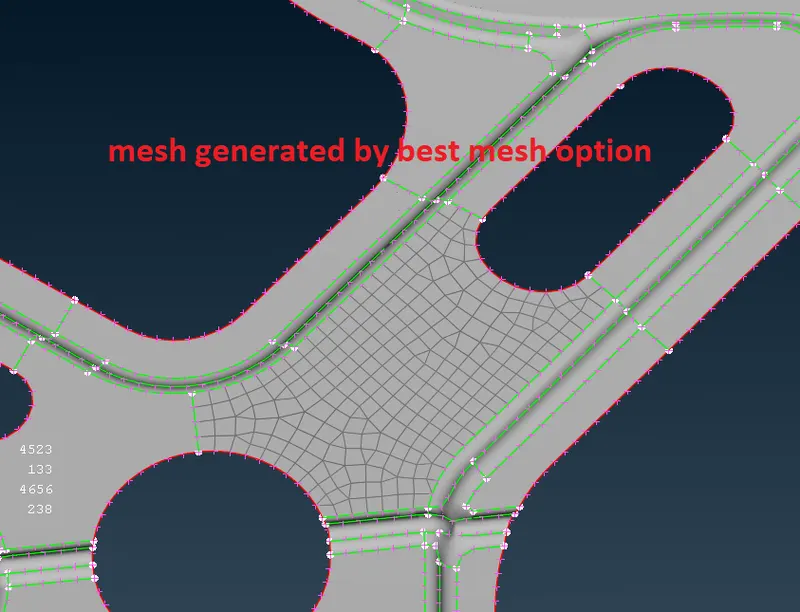
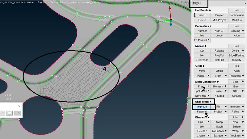
mesh flow can be improved by improve option
mesh module-shell mesh-improve-select mesh elements to increase their flow and resuses the trial number significantly.
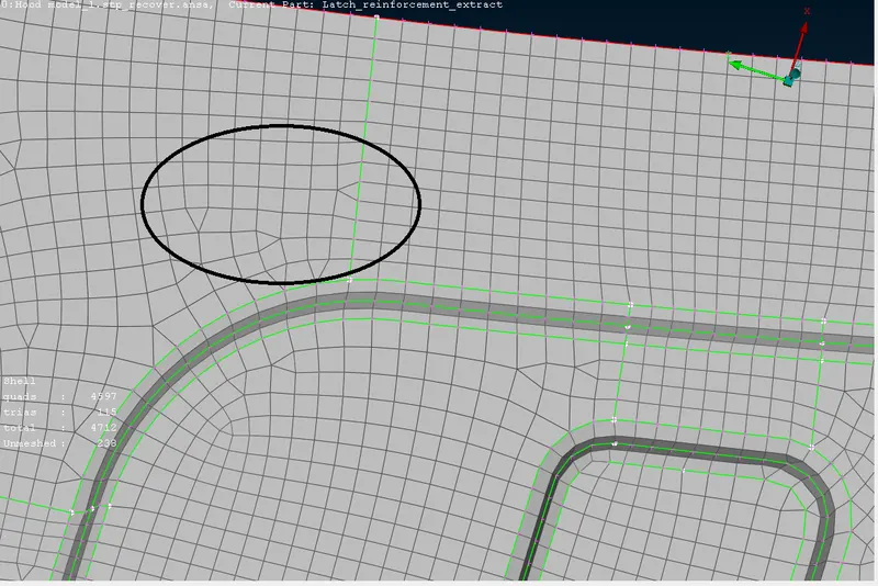
trias as shown above deal with split and swap options. the split option is used to move the trias forward, and sideways, joining the elements by right-clicking on the partition edge of the element, and the swap option moves the tria sideways.
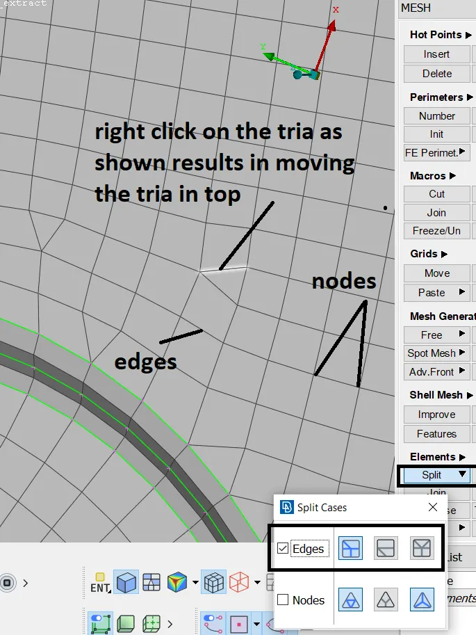
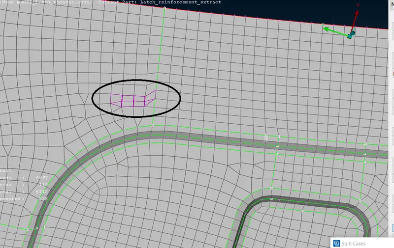
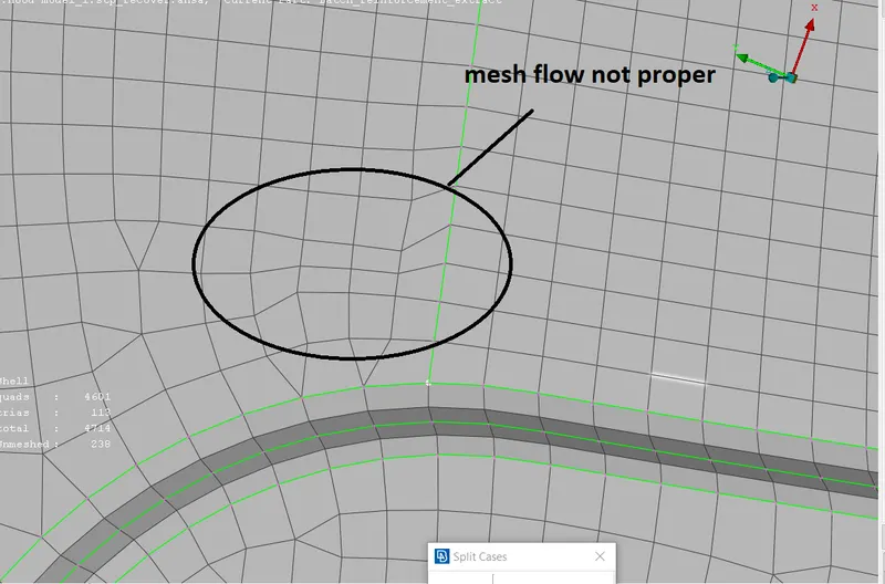
here smooth option plays a major role. we can also smooth the mesh while working with the split command itself by selecting improve option to smooth.
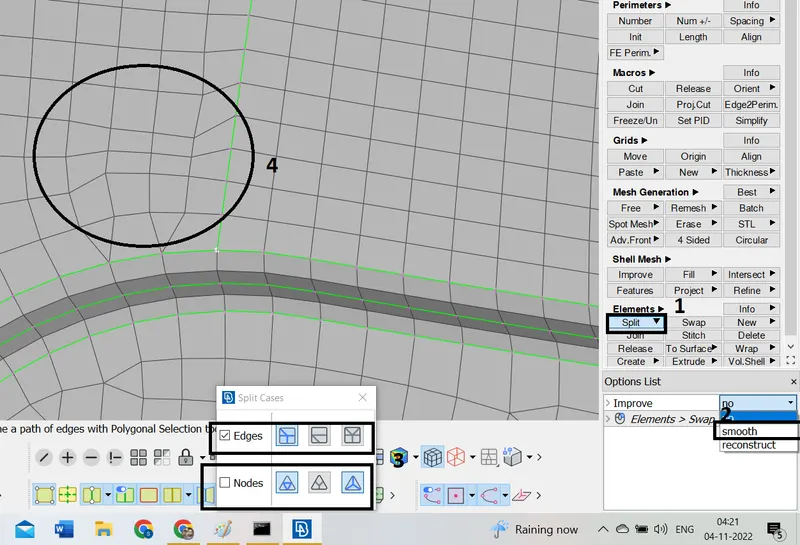
smoothing in the split option itself
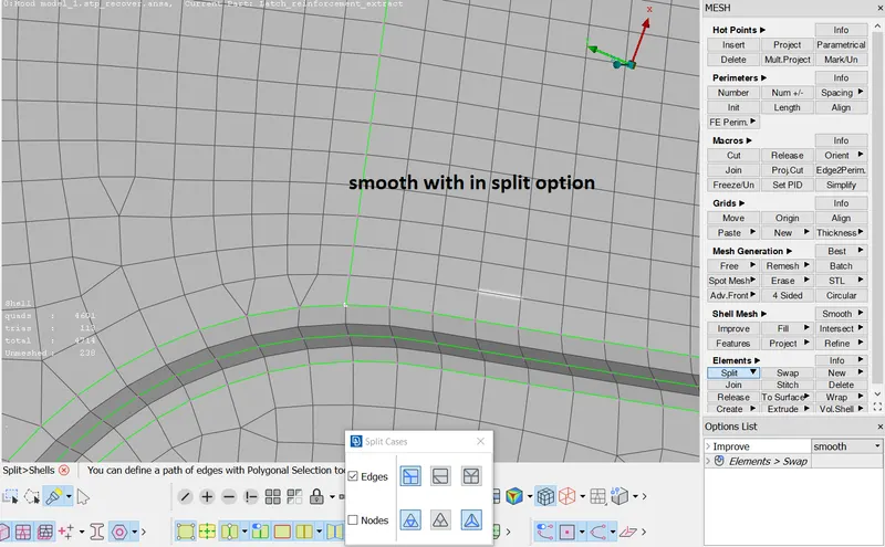
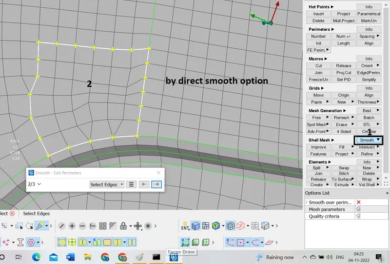
in both cases, we can observe the same results.
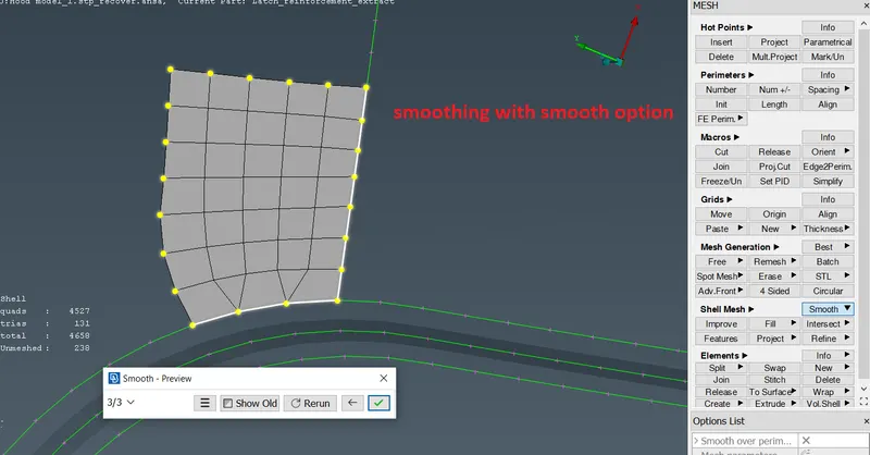
smoothing with a smooth option.
The below fig shows mesh flow in a featured area
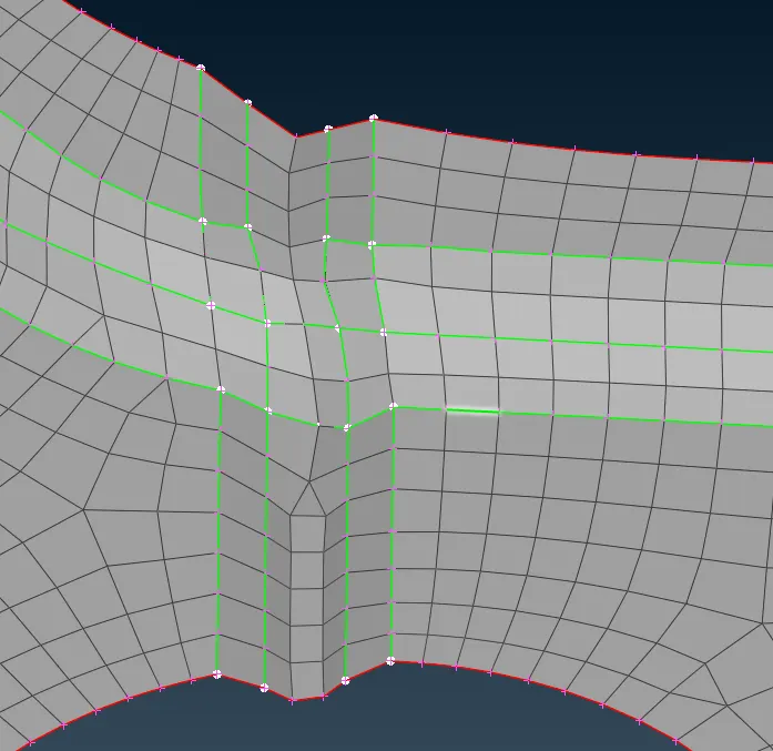
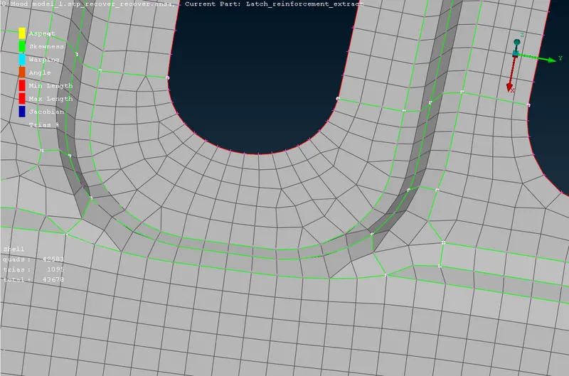
- trias on corners are not able to remove. Their absence leads to warpage errors and minimum element errors.
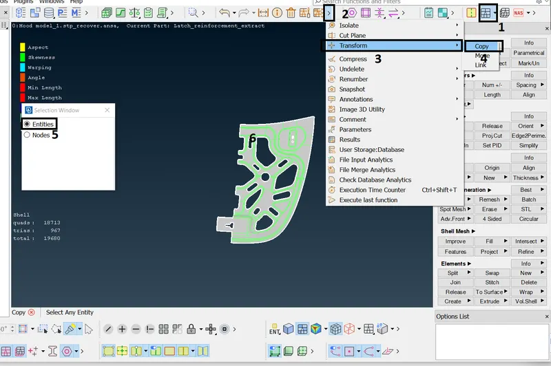
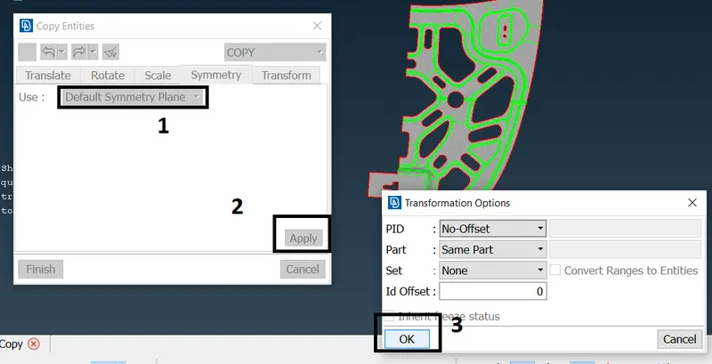
- after completing the meshing if the part is symmetry we need to reflect them to another side also this how it can be done.
- set into mesh module-then from utility tab click down arrow-choose 'transform'-copy(we need to copy in to another side)-choose entity-select the entities(includes surfaces and elements)-ok(middle mouse button)-
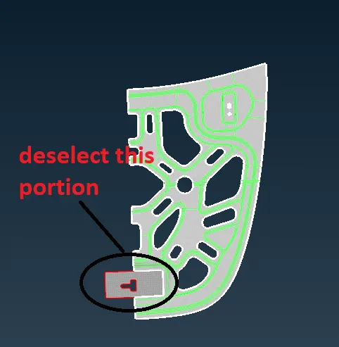
- in the above figure, one feature needs to be deselected from reflecting because it is not symmetry.
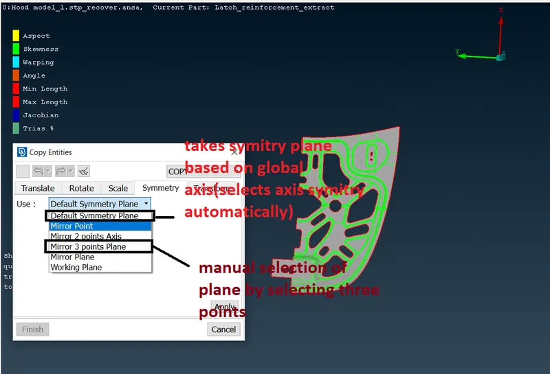
- using the default symmetry option
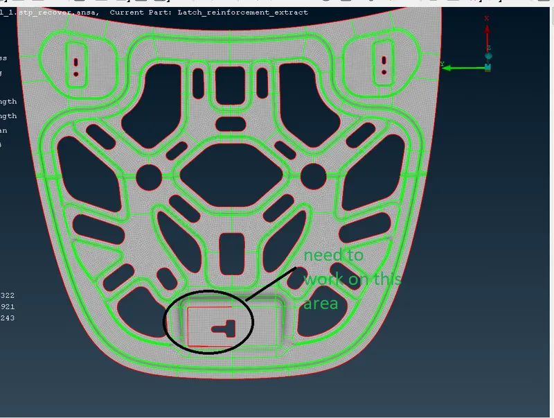
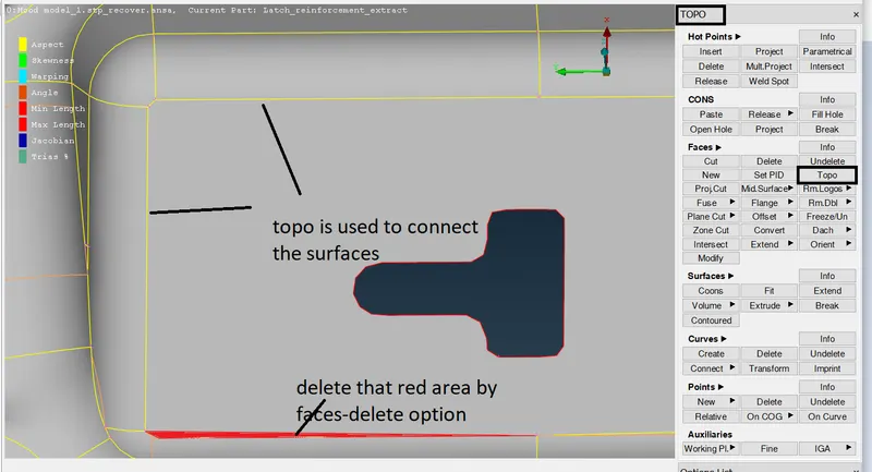
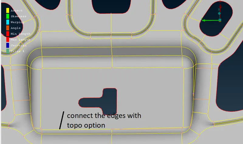
- as the topo option used after mesh we will miss the mesh in that area as shown below
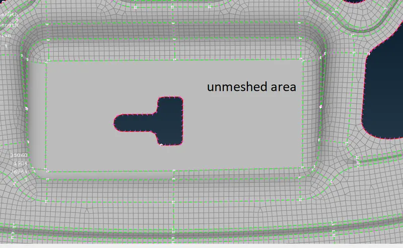
- mesh the unmeshed area as discussed above
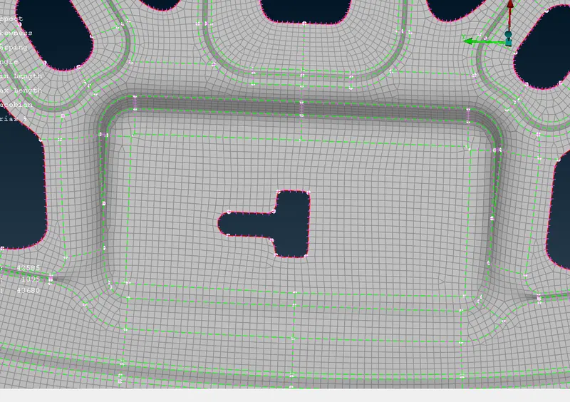
- overall PID with mesh
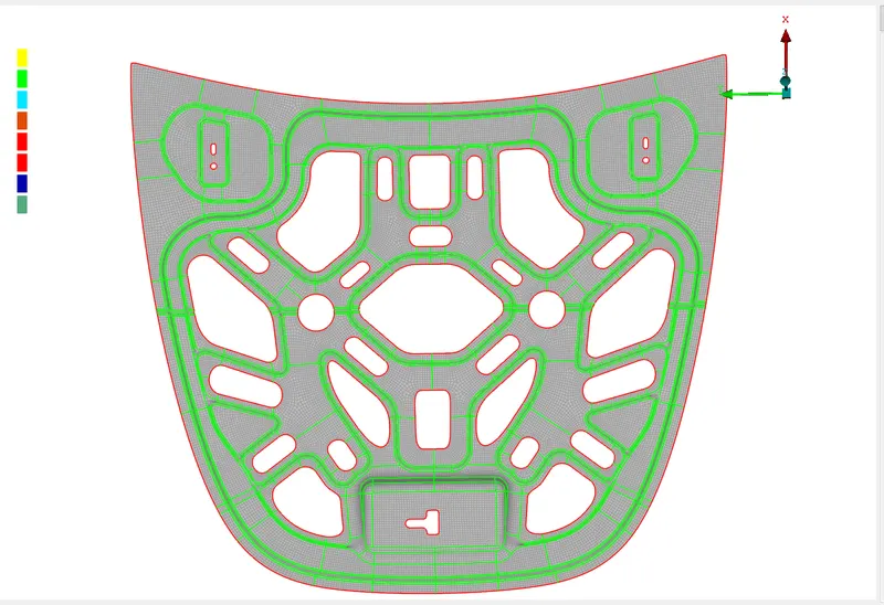
- over all meshing
quality checking:-
- here I updated the quality criteria values way before starting the meshing so, that I can work on both at a time also the mesh creates by the reference of quality criteria makes the job easier.
- Here is how we can update the quality criteria values.
- utilities tab-quality criteria-enter the values correspondingly-apply-ok.
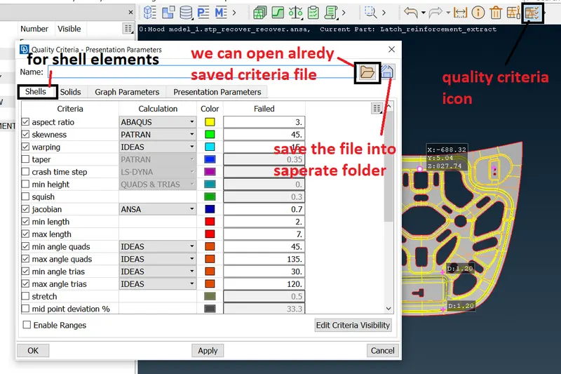
- elements failing for quality criteria can be solved by using the 'improve mesh' option, by dragging trias to make mesh finner in max element size failure case.
- after applying quality criteria to visualise the failure of elements followbelow steps
- change to mesh module-enable hidden option(which shows the elements failed for quality in respective failure colure so that we can identify the type of failure).
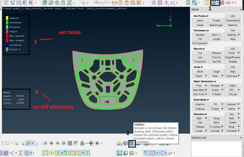
- above figure there are no off elements in the 4th step i.e., no elements failed.
remaining all pids can be meshed by following above steps itself.
hinge:-
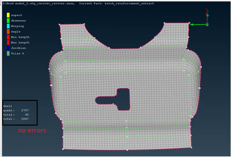
flanges:-
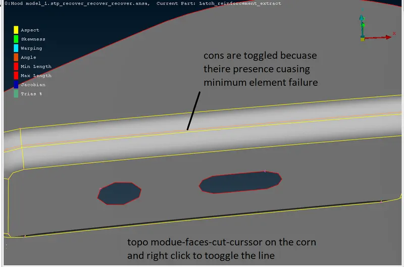
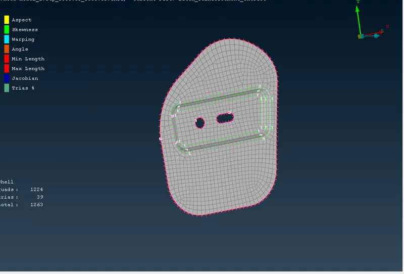
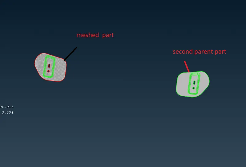
- in above as there are two flanges which are similar therefore meshing on one PID and transforming it onto the other side may save time this can be achieved by trans form-symmetry option
- utilities tab-transform-copy-symmetry-choose default symmetry plane(ansa automatically calculates the exact plane)-apply-ok
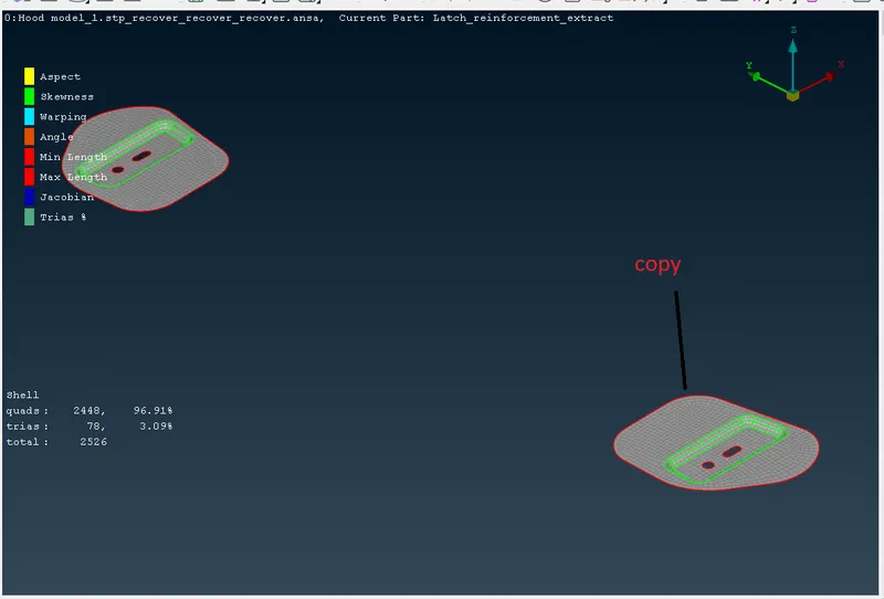
outer panel
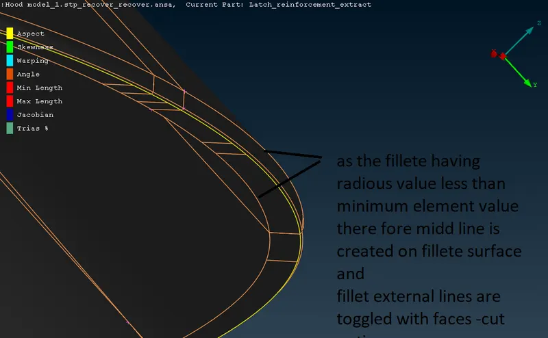
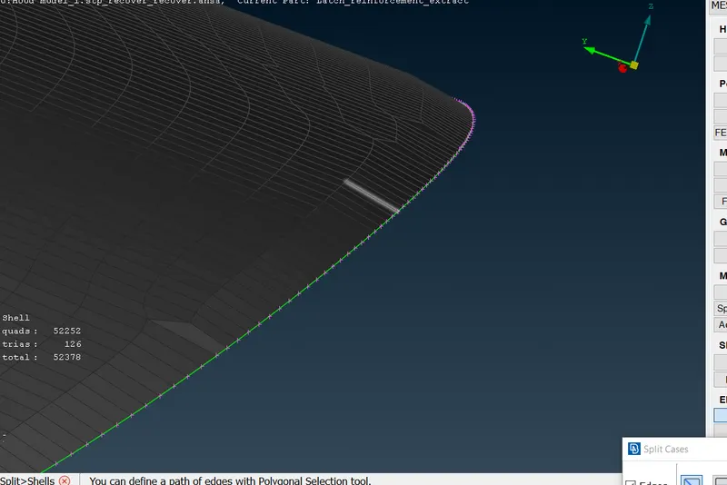
- fillet surface is captured with specifications as shown in task.
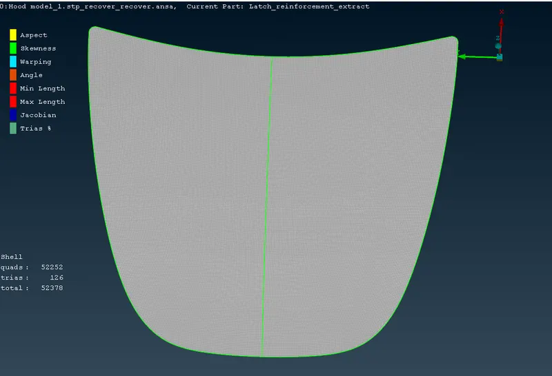
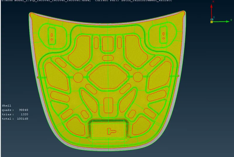
overall meshing
assigning thickness:-
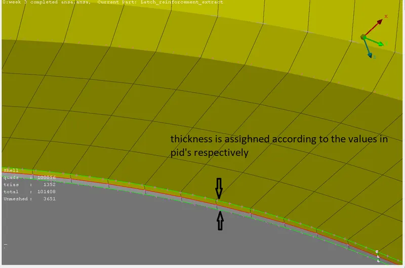
as this is a sheet metal component all the components have a uniform thicknesses.
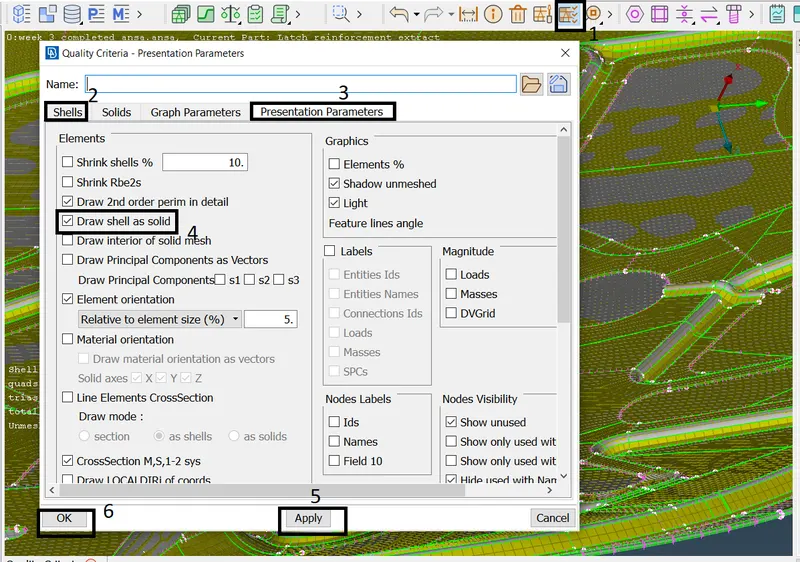
utility tab-quality criteria-import quality criteria or quality criteria is not updated in shells section-then change to presentation perimeters-check the 'draw shell as a solid' box -apply-ok.
note
file uploaded as two files because the whole file was not uploading.
files in a combination of
- inner and flange parts together and remaining in another file.