Week 2 - Flow over a Cylinder.
AIM:-
- Simulate the flow Over the cylinder and explain the phenomenon of Karman vortex street.
- Simulate the flow with the unsteady case and calculate the Strouhal Number for Re=100
- Plot the graph for the coefficient of drag and lift over a cylinder by setting the Reynolds number to 10,100,1000,10000 and 100000.
- Show that the flow has converged.
- Mention the quantities or plot which determine that the flow has converged.
OBJECTIVE:-
- Study and understand the simulation of flow over the cylinder and the phenomenon of Karman vortex street.
- Create a 2D geometry in the design modeler as per the given dimensions.
- Generate proper mesh with an effective inflation layer over the cylinder wall
- Simulate solution into two-part: in the first part, simulate the flow with steady and transient case and calculate the Strouhal Number for Re-100
- In the second part, calculate the coefficient of drag and lift over a cylinder by setting all given Reynolds numbers using a steady solver.
- Discuss the effect of Reynolds number on the coefficient of drag.
- show the flow has converged with the help of the quantities or plot which determine that the flow has converged.
- Plot the graph for the coefficient of drag and coefficient of lift.
- Plot to show vortex shedding behind the cylinder.
THEORETICAL EXPLANATION:-
KARMAN VORTEX STREET
In fluid dynamics, a Karman vortex street is a repeating pattern of swirling vortices, caused by a process known as vortex shedding, which is responsible for the unsteady separation of flow of a fluid around blunt bodies. A vortex street will form only at a certain range of flow velocities, specified by a range of Reynolds numbers (Re), typically above a limiting Re value of about 90. The (global) Reynolds number for a flow is a measure of the ratio of inertial to viscous forces in the flow of a fluid around a body or in a channel and may be defined as a non-dimensional parameter of the global speed of the whole fluid flow.
THE STROUHAL NUMBER
The Strouhal number represents the ratio of inertial force. due to the local acceleration of the low to the inertial forces because of the Convective acceleration.
Depending on the time scale of the problem this ratio may be order unity and therefore inflows characterized by a periodic motion. the Strouhal number is associated with tie oscillation of the flow due to the inertial forces relative to the changes in velocity due to the convective accelerate. of the few fields thus, an alternative definition of the Strouhal number better suited to periodic flows is given by the following expression importance not obvious. For high Strouhal numbers oscillation dominate the flow while at low Strouhal number the oscillation is swept by the fast-moving fluid.
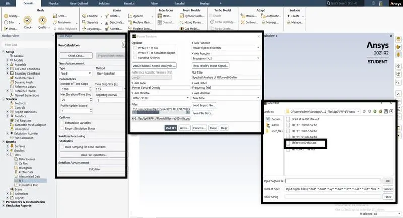
In Fluent, one can directly calculate Strouhal Number using FFT results
CO-EFFICIENT OF DRAG
In fluid dynamics, the drag coefficient (Cd)is a dimensionless quantity that is used to quantify the drag or resistance of an object in a fluid environment, such as air or water. It is used in the drag equation in which a lower drag coefficient indicates the object will have a less aerodynamic or hydrodynamic drag. The drag coefficient is always associated with a particular surface area.The drag coefficient of any object comprises the effects of the two basic contributors to fluid dynamic drag: skin friction and form drag. The drag coefficient of a lifting airfoil or hydrofoil also includes the effects of lift-induced drag. The drag coefficient of a complete structure such as an aircraft also includes the effects of interference drag
CO-EFFICIENT OF LIFT
The lift coefficient (CL) is a dimensionless coefficient that relates the lift generated by a lifting body to the fluid density around the body, the fluid velocity, and an associated reference area. A lifting body is a foil or a complete foil-bearing body such as a fixed-wing aircraft. CL is a function of the angle of the body to the flow, its Reynolds number, and its Mach number. The section lift coefficient refers to the dynamic lift characteristics of a two-dimensional foil section, with the reference area replaced by the foil chord.
CALCULATION:-
Velocity calculation
`Re=(rho*l*V)/(mu)`
`V=(Re*mu)/(rho*l)`
Re=100
`Rho = 1 (kg)/(m^3)`
`Mu = 0.05(N.s)/m^2`
L=2m
PROCEDURE: -
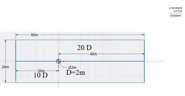
*The geometry is created as mentioned dimensions in the space claim.
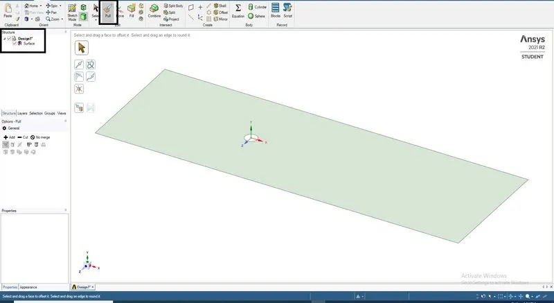
*The geometry is converted into a surface by pull option and the geometry.
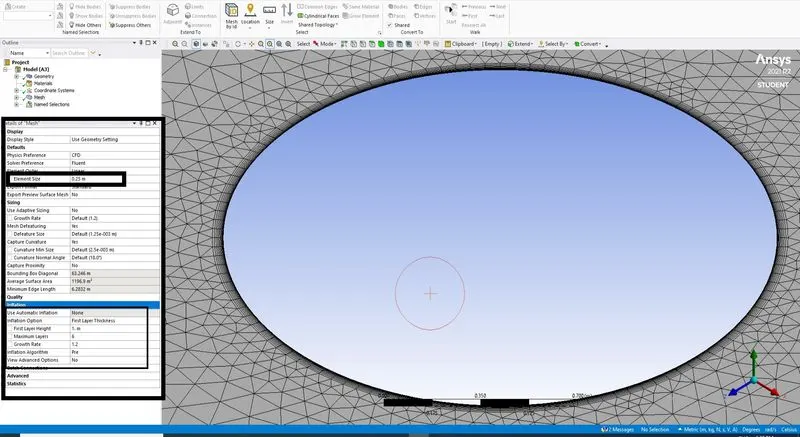
*The mesh is created for an element size of 0.25m and the quality of the elements we more than 40%, Mesh methods were used to create triangle elements and Inflation was added for the mesh by 12 layers near the circle region.
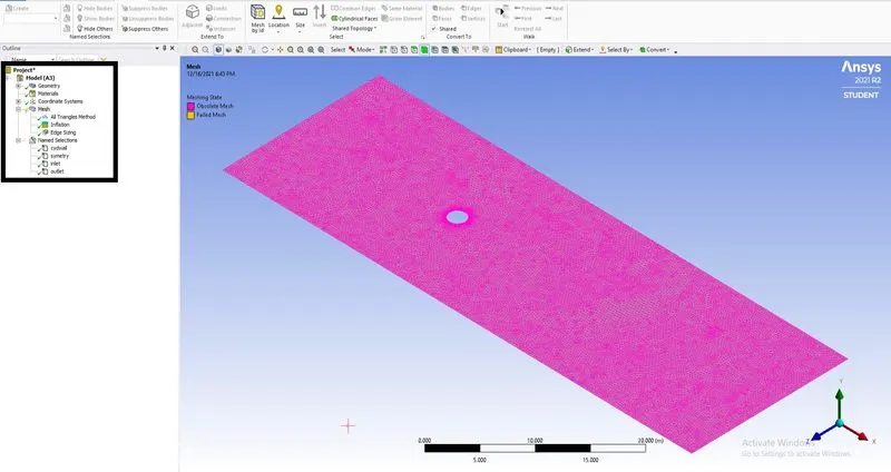
*The mesh generated was a obsolete mesh and Names were assigned for the wall and the inlet, outlet.
*The Setup workbench is started and given recommended parameters.
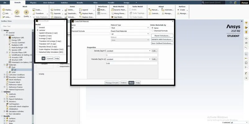
*The model was turned on for laminar flow model ,The material is been added, the air is been initiated with specific values at both the inlets.
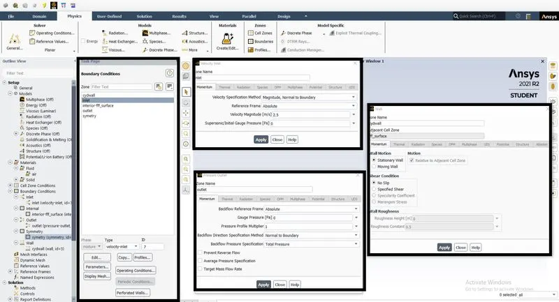
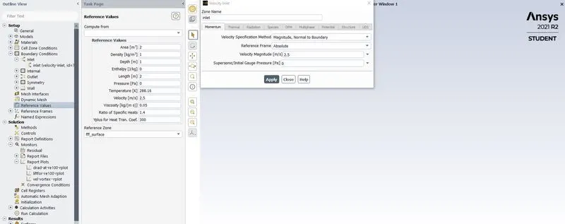
*Boundary Conditions are applied on the inlet with velocity values of 2.5m/s for Re 100, outlet with pressure at zero, and the wall with No-slip conditions.
*Report definition is done by creating a report for Coefficient of drag, Coefficient of, lift and vortex shedding behind the cylinder.
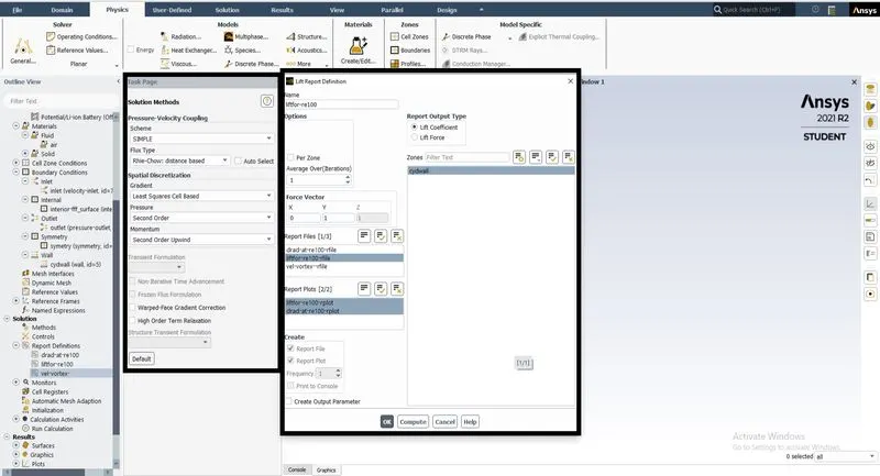
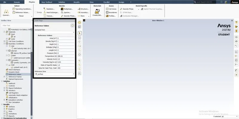
*Reference value is checked for the area, length and velocity parameter and their values.
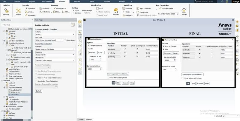
*Solution method is selected for SIMPLE method and the residuals is unselected for check convergence.
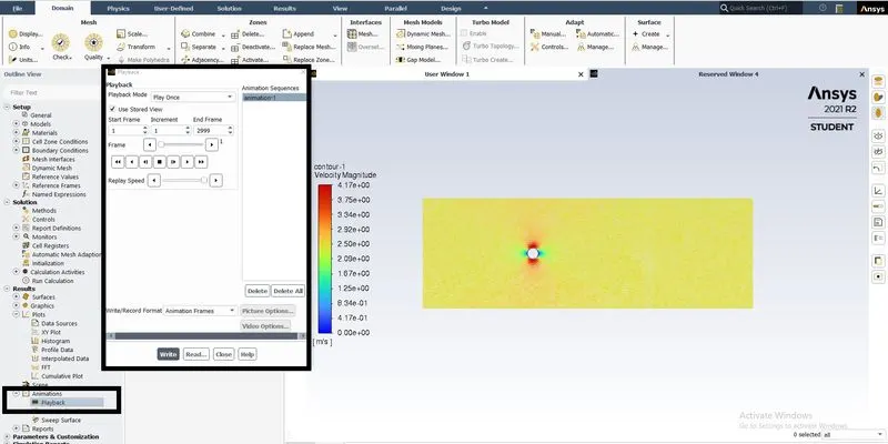
*Animation request is done for vortex shedding behind the cylinder for final visualization of the phenomenon.
CASE 1 a
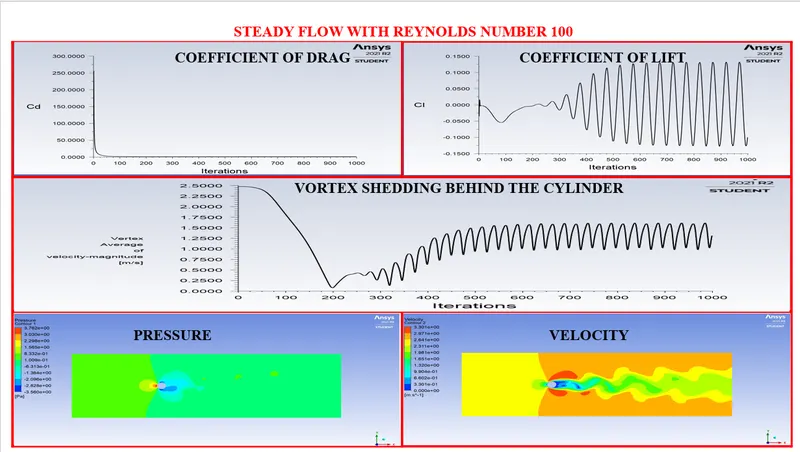
*Reference value is checked for the area, length and velocity parameter and their values for Re 100.
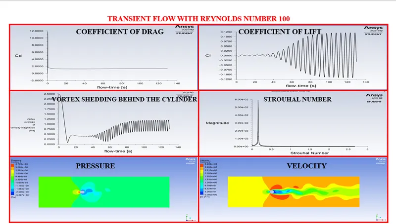
*The Coefficient of drag, Coefficient of, lift and vortex shedding behind the cylinder are plotted to show the model has reached convergence and contours for pressure and velocity.
CASE 1 b
*Reference value is checked for the area, length and velocity parameter and their values for Re 100.
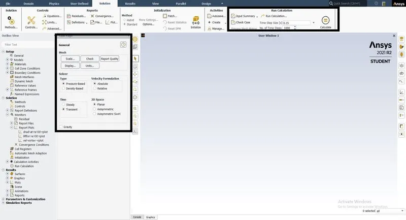
*The case is run for transient flow condition and the time step value with number of time step is added and computed for this case.
* In Fluent, one can directly calculate Strouhal Number using FFT results and selecting the Coefficient of, lift file for inputs. the result can be in write format and graph format.
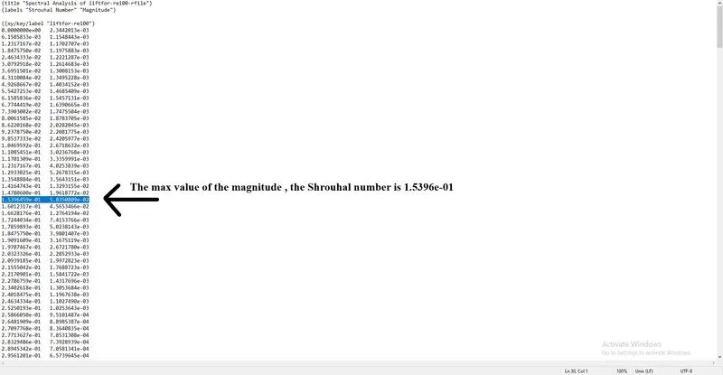
*The value of Strouhal Number for max value of magnitude is 0.15 units.
*The Coefficient of drag, Coefficient of, lift and vortex shedding behind the cylinder are plotted to show the model has reached convergence, Strouhal Number and contours for pressure and velocity.
CASE 2 a
Velocity calculation
`Re=(rho*l*V)/(mu)`
`V=(Re*mu)/(rho*l)`
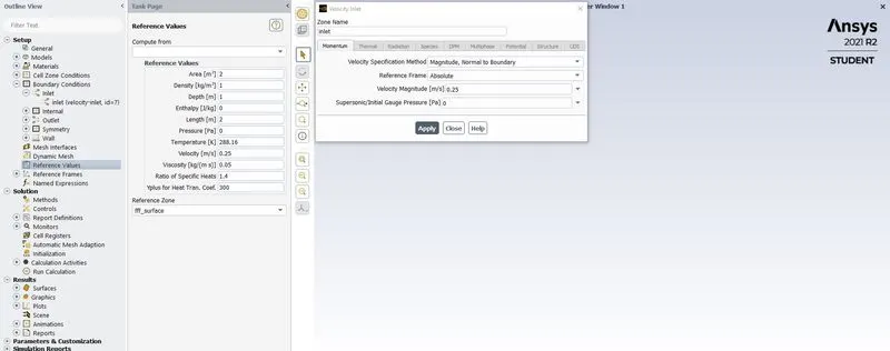
Re=10
`Rho = 1 (kg)/(m^3)`
`Mu = 0.05(N.s)/m^2`
L=2m
`V= (10*0.05)/(1*2)`
`V=0.25 (m)/s`
*Reference value is checked for the area, length and velocity parameter and their values for Re 10.
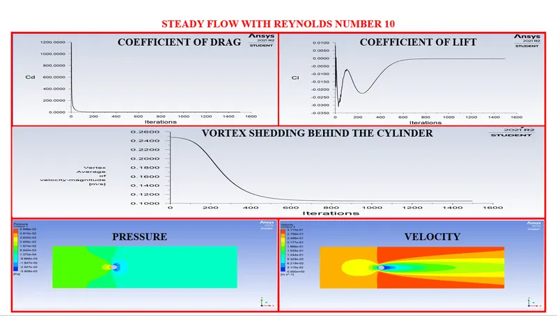
*The Coefficient of drag, Coefficient of, lift and vortex shedding behind the cylinder are plotted to show the model has reached convergence and contours for pressure and velocity.
CASE 2 b
Velocity calculation
`Re=(rho*l*V)/(mu)`
`V=(Re*mu)/(rho*l)`
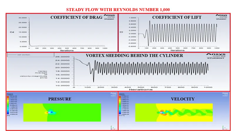
Re=1,000
`Rho = 1 (kg)/(m^3)`
`Mu = 0.05(N.s)/m^2`
L=2m
`V= (1000*0.05)/(1*2)`
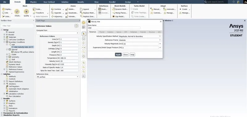
`V=25 (m)/s`
*Reference value is checked for the area, length and velocity parameter and their values for Re 1,000.
*The Coefficient of drag, Coefficient of, lift and vortex shedding behind the cylinder are plotted to show the model has reached convergence and contours for pressure and velocity.
CASE 2 c
Velocity calculation
`Re=(rho*l*V)/(mu)`
`V=(Re*mu)/(rho*l)`
Re=10,000
`Rho = 1 (kg)/(m^3)`
`Mu = 0.05(N.s)/m^2`
L=2m
`V= (10000*0.05)/(1*2)`
`V=250 (m)/s`
*Reference value is checked for the area, length and velocity parameter and their values for Re 10,000.
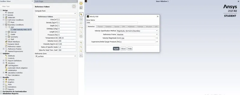
*The Coefficient of drag, Coefficient of, lift and vortex shedding behind the cylinder are plotted to show the model has reached convergence and contours for pressure and velocity.
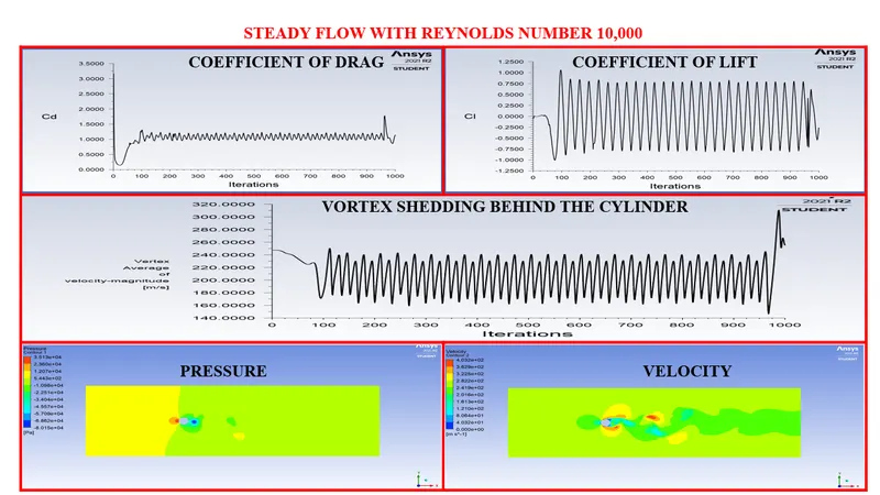
CASE 2 d
Velocity calculation
`Re=(rho*l*V)/(mu)`
`V=(Re*mu)/(rho*l)`
Re=1,00,000
`Rho = 1 (kg)/(m^3)`
`Mu = 0.05(N.s)/m^2`
L=2m
`V= (100000*0.05)/(1*2)`
`V=2500 (m)/s`
*Reference value is checked for the area, length and velocity parameter and their values for Re 1,00,000.
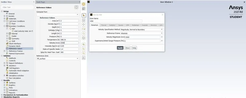
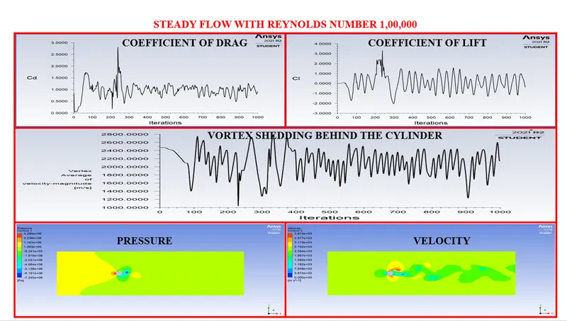
*The Coefficient of drag, Coefficient of, lift and vortex shedding behind the cylinder are plotted to show the model has reached convergence and contours for pressure and velocity.
CONCLUSION
- Karman Street Phenomenon for flow Over cylinder studied and observed in this project In a comparison of steady-state and transient methods, analyzing a laminar flow, for Reynolds number more than 100 it is vital to use the time-dependent momentum equations to resolve the vortex-shedding characteristics
- As the Reynolds number increased further, the vortices are shed alternately from the upper and lower-cylinder surface at a definite frequency depending on the Reynolds number. And for the value of Re more than 1000, the flow starts to transform from laminar to turbulent
- The value of Strouhal Number for the max value of magnitude is 0.15 units.
- As the Reynolds number increases the inertial forces start to dominate over viscous forces which lead to a significant increase in drag and also, a rise in fluctuation in the coefficient of lift
- With the streamlined plot, we can observe that with the increase in the value of the Reynolds number the flow becomes more unsymmetrical which induces increase levels of turbulence in the boundary layer and wall region.