Week 2:- BiW Fixture Basics Challenge
BIW FIXTURE BASIC CHALLANGE
1.WHAT IS THE PROCESS OF PROJECT EXECUTION ACTIVITY ?
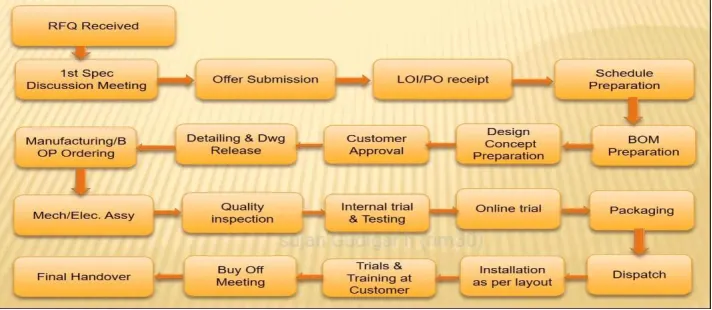
FIG1:- PROJECT ACTIVITIES
- THE ABOVE FIGURE SHOWS THE PROJECT EXECUTION ACTIVITIES
- THE ACTIVITY CONSIST OF VARIOUSSTEPS , AS THOUGHIT STARTS FROM RFQ RECIVED TILL IT BEEN FINAL HANDOVER TO COUSTOMER THE DESIGN TEAM HAS A GRIP OF EACH AND STAGE (WERE IF IT GOES TO MANIFACTURING OR QUALITY ) THERE IT SHOULD HAVE SOME CONTRUBUTION OF DESIGN.
- WHAT ARE THE TYPES OF JOINING PROCESSES ?
JOINING PROCESSES ARE CHARACTERISED BY THEIR ABILITY TO FUSE OR JOIN , TWO OR MORE COMPONENTS FOR THE PURPOSE OF CREATING A DIFFERENT OBJECT,READY TO SELL CONSUMER PRODUDTS.MOST MATERIALS CAN BE JOINED AND THERE ARE TYPOICALLY MULTIPLE WAYS TO JOIN THEM.TWO BY FOURS, FOR INSTACE NAILED OR BOLTED TOGETHER , WHEREAS SHEET METAL CAN BE WELDED OR SOLDERED TOGETHER.
COMMON TYPES OF JOINING PROCESS.
- WELDING
- BRAZING
- SOLDERING
- BONDING
- NAILING
- SCREWING
- BOLTING
- REVIETING
- CLINHING
- STAPLING
- PRESS FITTING
1.WELDING:Welding is a fabrication process whereby two or more parts are fused together by means of heat , pressure of both forming a join as a part cools. Welding is usually used on metals and thermoplastics but can also be used on woods.
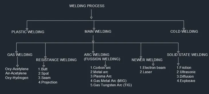
2.BRAZING:Brazing is a metal-joining process in which two or more metal items are joined together by melting and flowing a filler metal into the joint, with the filler metal having a lower melting point than the adjoining metal.
- GAS BRAZING
- FURNACES BRAZING
- ELECTRIC BRAZING
- IMMERSION OR DIP BRAZING
- TORCH BRAZING
- INDUCTION HEATING BRAZING
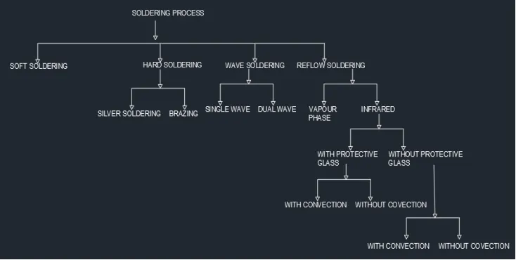
- SOLDERING:-Soldering is a joining process used to join different types of metals together by melting solder. Solder is a metal alloy usually made of tin and lead which is melted using a hot iron. The iron is heated to temperatures above 600 degrees Fahrenheitwhich then cools to create a strong electrical bond.
- BONDING:-Adhesive Bonding is the process of joining two surfaces together, usually with the creation of a smooth bond. This may involve the use of glue, epoxy, or one of a wide range of plastic agents which bond either through the evaporation of a solvent or through curing via heat, time, or pressure.
- NAILING:-Nailing is effected on a firm, not springy support. The nail, when being driven in, is held and guided with the left hand at the shank until it sticks sufficiently deep and tight in the wood. The hammer is taken with the right hand at the end of the handle; hammering is done from the wrist. The hammer must be guided slackily and without clenching. When driving in the nail, the direction of the blows must be the longitudinal axis of the nail. Nailing is done with the hammer face.
- SCREWING:-When several screws shall be driven into a workpiece, then the individual parts have to be secured against shirting.Pre-drilling and/or pre-cutting is necessary in any case!To maintain the screwing-in and/or drawing-out resistance, the screw holes must not be pre-drilled too large and not too deep. The end of the insert of the screw driver shall have the width of the screw head diameter. It must fit exactly into the screw slot. When driving in the screw, the screw head and the end of the insert of the screw driver have to be guided with the left hand
- BOLTING:-In this metal joining process, the metallic partsare joined together by means of Bolt/Screw (and/or nut). This Process is widely used in assembling of parts are to be joined temporarily or joints which require periodic maintenance. Two main types of loads on bolted joints: Tension Shear Bolting.
- REVITING:-Riveting is a forging process that may be used to join parts together by way of a metal part called a rivet. The rivet acts to join the parts through adjacent surfaces. A straight metal piece is connected through the parts. Then both ends are formed over the connection, joining the parts securely.
- CLINHING:-The clinching process is a method of assembling sheet metal without welding or fasteners. With this joining technique, metal parts are deformed locally without the use of any consumables. Coated and painted sheet metals can also be joined together without altering the surface finish.
- STAPLING:-Stapling means the process of joining which results in each Share and Unit being and remaining Stapled to each other; Sample 2. Stapling means the linking together of all the rights and obligations which attach to a Stapled Security;
- PRESS FITTING:-In engineering terms, a press fit— also known as an interference fit— is the fastening of two parts that is achieved by normal force, friction and cold welding. This happens when a shaft is inserted tightly into a slightly smaller hole in another part, with the interference holding both parts in place.
- WHAT IS RESISTANCE WELDING & ITS APPLICATION IN THE AUTOMOBILE SECTOR ?
- RESISTANCE WELDING :-Resistance welding is a liquid state welding process, in which a metal-to-metal joint is made in a liquid or molten state. The resistance welding is also known as the Thermos-electricprocess in which heat is produced at the interface surfaces of welding plates due to electrical resistance and controlled low pressure is applied to these plates to form the weld joint.
Following are the 5 different types of resistance welding:
- Spot resistance welding
- Projection resistance welding
- Seam resistance welding
- Flash resistance welding
- Butt resistance welding
1. Spot Welding
In this process, the parts to be joined are held firmly between two heavy electrodes, which are connected in the secondary circuit of the step-down transformers. The maximum resistance exists at the contact surface of the two parts being joined and high heat is developed.
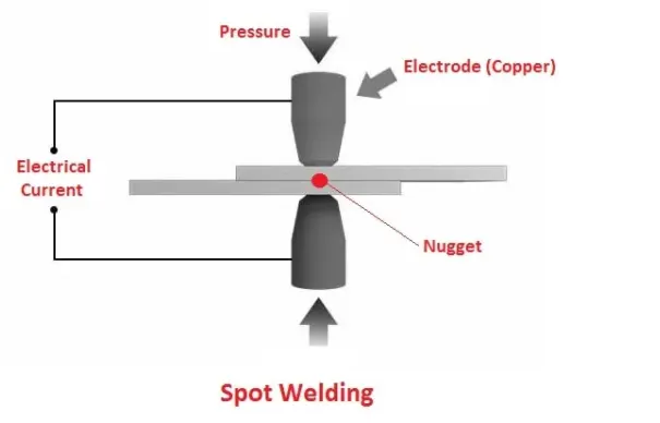
The heat developed fuses the work piece at the electrode spot. At the same time pressure is applied to the workpiece through the electrodes and welding takes place. Current supply and amount of time must be sufficient for proper melting of interface surfaces.
2. Projection Welding
The projection welding is similar to spot-welding but uses a flat electrode. In this current flow and resultant heating are localized of the projection, hence thick parts can be joined that cannot be joined by spot welding.
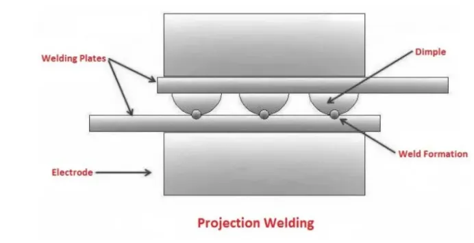
The workpiece is held between the electrode and a large number of current passes through it. A small amount of pressure is employed through the electrodes on the welding plates. The current passes through the dimple which melts it and causes the pressure dimple to level and form a weld.
3. Seam Welding
Similar to spot welding but in this a continuous weld is produced by passing the work between rotating wheel-shaped electrodes, which exert the welding pressure and also conduct the welding current. It may be continuous or intermittent.
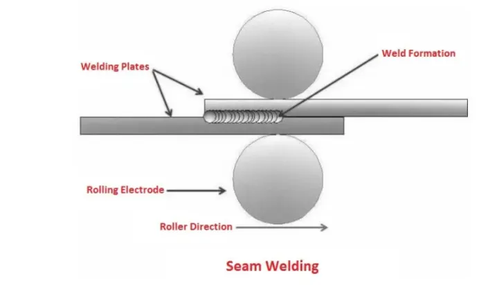
First, the rollers are exposed to the work piece. A high amount of ampere current is passed through these rollers. This interface surfaces will melt and form a weld joint. Now the rollers start rolling on the work plates. This will form a continuous weld joint.
The movement time of the weld and electrode is controlled to assure that the weld overlaps and the work piece is not too hot. It is used to make airtight joints.
4. Flash Welding
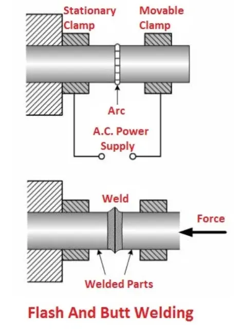
It is a type of resistance welding process, which can be used for joining together the ends of sheets, wires, rods or tubes. Here electric arc is produced in the gap between the work pieces until the welding temperature is attained. Then pressure is applied to produce a continuous weld.
5. Butt Welding
The butt welding differs from flash welding, in that no arcing takes place between the surfaces being joined. The heat is produced solely by the electric resistance at the butting surface to the flow of current.
Application of Resistance Welding
Following are the applications of resistance welding:
- It is broadly used in the automotive industries.
- Projection welding is generally used in the production of nut and bolt.
- Seam welding is used to perform leak prove joint required in small tanks and boilers etc.
- Flash welding is adopted for welding pipes and tubes.
- Resistance welding is used in mass production for welding sheet metal, wire and tubes.
- It is used in welding bars, boxes, cans, rods, pipes and frames metals of medium and high resistance materials such as steel, stainless steel, monei metal and silicon bronze which are easy to weld.
- It is used in welding aircraft and automobile parts
- It is used for making cutting tools.
- It is used for making fuel tanks of cars, tractors etc.
- It is used for making wire fabrics, grids, grills, mesh weld, containers etc.
-
4.What is fusion welding & types of fusion welding with its application in the automotive sector?
Fusion-welding processes use heat to melt the base metals. In many fusion welding operations, a filler metal is added to the molten pool to facilitate the process and provide bulk and strength to the 2 welded joint. A fusion-welding operation in which no filler metal is added is referred to as an autogenous weld. The fusion category includes the most widely used welding processes, which can be organized into the following general groups (initials in parentheses are designations of the American Welding Society): Arc welding (AW).Arc welding refers to a group of welding processes in which heating of the metals is accomplished by an electric arc, as shown in Figure 1. Some arc welding operations also apply pressure during the process and most utilize a filler metal.
Arc Welding Processes - with the most common processes being: Shielded Metal Arc Welding (SMAW), also known as manual metal arc welding (MMA or MMAW), flux shielded arc welding or stick welding. Suitable for welding ferrous and non-ferrous materials in all positions.
Metal Inert Gas Welding (MIG) and Metal Active Gas Welding (MAG), also known as Gas Metal Arc Welding (GMAW). MIG and MAG welding are the most common arc welding processes, in which an electric arc forms between a consumable wire electrode and the workpiece leading them to melt and join. Both use a shielding gas to protect the weld from airborne contaminants, or oxidation in the case of MIG welding.
Tungsten Inert Gas Welding (TIG), also known as Gas Tungsten Arc Welding (GTAW). This arc process uses a non-consumable tungsten electrode to create the arc between the electrode and the base plate. An inert shielding gas is used to protect from oxidation or other atmospheric contamination. This process can be used autogenously on thin parts, but will require the addition of a wire, rod, or consumable to be added for thicker parts.
Plasma Arc Welding (PAW). This process uses an electric arc created between an electrode and the torch nozzle. The electric arc ionises the gas (usually argon) in the chamber creating what is called a 'plasma.' It is then forced through a fine bore copper nozzle that constricts the arc and directs it to the workpiece, allowing the plasma arc to be separated from the shielding gas (which is usually made from a mixture of argon and hydrogen).
Submerged Arc Welding (SAW). This frequently-used arc welding process uses a continuously-fed consumable electrode and a blanket of fusible flux which becomes conductive when molten and provides a current path between the workpiece and the electrode. The flux also prevents spatter and sparks while suppressing ultraviolet radiation and fumes.
Flux Cored Arc Welding (FCAW). Developed as an alternative to SMAW, this process uses a continuously fed consumable electrode with a flux and a constant voltage or constant current power supply. Sometimes using a shielding gas this process can also just use the flux to provide protection from the atmosphere
Application of fusion welding
Fusion welding processes are commonly used across a range of industries including aerospace, automotive and construction amongst others. Used to join metals for a variety of applications, fusion welding is also used to create artwork by a growing community of artists.
- WHAT IS THE 3-2-1 PRINCIPLE?
The 3-2-1 principle states that the six locators are sufficient to restrict the required degree of freedom of any work piece. In this, motion is restricted using clamps and locators. A three-pin base can restrict five motions and six pins restrict nine motions.
Types Of Locators used In Jig And Fixture For supporting :
The location arrangement depends on the type of operation, degrees of required accuracy.
- Flat locators: These are used for the location of the flat machined surfaces of a component.
- Cylindrical locators:These are used for the location of components with drilled holes.
- Conical locators:These locators are used to support the work pieces with cylindrical holes.S
- Jack pin locators:These locators support rough work pieces.
- Drill bush locators:These locators hold and locate the cylindrical workpieces.
- Vee locators:These locators hold circular and semicircular workpieces.
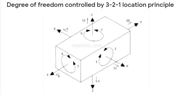
In this method, 9 degrees of freedom is controlled.
Pins A, B, C on the base plane ( a plane parallel to the plane which contains X and Y axis) restrict the rotation of component about X axis and Y axis. It also limit the downward movement of component along z axis. Ie. 1,2,3,4 and 5 degrees of freedom is restricted.
Pins D, E is in plane parallel to the plane containing X and Z axes. It prevents the rotation of component about Z axis (6, 7 degree of freedom) and the movement of the body in along Y axis towards one direction (8 degree of freedom).
- Basic Rules For Location
- Choosing Locating Surfaces
The last pin F is in a plane parallel to plane contains Y and Z axes. It restricts the movement component along X axis in one direction.
Three remaining degree of freedom 10, 11, 12 is unrestricted. It facilitates the loading of the component in the fixture. This three degree of freedom may restrict after loading of component by using clamping devices.
6.Define Body coordinate system?
A constant rotation about an axis written in the Body system is made up of the three rotations. The origin of the body coordinate system will be at the center of mass.The axes of the body coordinate system will be the principal axes of the object. These axes are rotating with the object.
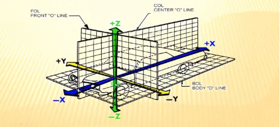
- Elaborate Body plane system & its essentials?
Body planes are hypothetical geometric planes used to divide the body into sections. They are commonly used in both Car body and anatomy to describe the location or direction of bodily structures. Reference planes are the standard planes used in anatomical terminology and include:
- The sagittal plane (lateral or Y-Z plane)divides the body into sinister and dexter (left and right) sides. The midsagittal (median) plane is in the midline through the center of the body, and all other sagittal planes are parallel to it.
- The coronal plane(frontal or Y-X plane) divides the body into dorsal and ventral (back and front) portions. It also separates the anterior and posterior portions.
- The transverse plane (axial or X-Z plane)divides the body into superior and inferior (head and tail) portions. It is typically a horizontal plane through the center of the body and is parallel to the ground.
While these are the major reference planes of the body, other planes are commonly used in relation to these three. A longitudinal plane is any plane perpendicular to the transverse plane, while parasaggital planes are parallel to the saggital plane.
The coronal plane, the sagittal plane, and the parasaggital planes are examples of longitudinal
planes.