Week 3:- BiW Fixture Design Methodologies Challenges
- What is design methodology ?
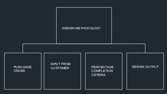
Design methodologies is nothing but the steps followed during the concepts designed stages of design .the various stages of design methodologies are ,
What is a purchase order
A purchase order is a contract between the buyer and the seller and it gives specific information like product or services to be delivered, delivery date, and any other terms and conditions including the price. The purchase order is also called as ‘PO’
What was the input from customer
- Functional Requirements.
- Preferred Standard Components.
- Car products.
- L
- Ergo data.
- Weld Study.
- Standard Detailing tempelets.
Functional requirement:The purpose or the function of the fixture will be given as input from the customers like what are the fixture is going to do I.e welding , gluing riveting or whether its a checking fixture etc.
Preferred standard components: As we know different companies follow different standards, we will be following the standard followed by the customers.by following standards the time of designing and manufacturing of parts will be saved , which will be automatically minimized the time of the projects .as for the standard parts ,it can be easily replaced from the used fixture to the new fixture.which reduce the cost.
Car products: The inputs we get from car products are GD&T, part list, Cad files of car part, clamp plan, Product assembly process sheet.
Layout: Layout shows the entire assembly plan to understand the process. Layout provides the information of flow of parts, station pitch,robot stations, Accessor ies like tool changers & tip dressers.sub assembly links, plat form height,loading/unloading sequence/height.
Ergo Data: As same as preferred standards, different companies follow different standards of Ergo data. We have to fol ow the customer standards of Ergo data. The inputs of Ergo data will given by the customer mostly in case of manually operated fixtures/manual fixtures. The Ergo data is mainly used to make the operator comfortable which may leads to improve the efficiency in cycle time & production. Ergo data provides inputs like Platform height, maximum & minimum reach from operator to f ixture, maximum & minimum height of the f ixture, whether the child parts/ assemblies are visible while clamping or loading & unloading.Also provides information like Loading height, working safety zone of operator, etc.
Weld study:Weld study is the important inputs given by the customer.it gives details about the study of particular gun that we use for welding. Also the data s like no. Of well,position of weld in the components will be given. In short, weld study includes weld gun detais, weld matrix & weld points.
Standard detailing Template s: This inputs include the detailing templates of 2D cad drawing as per the customer standards.So we have to follow the detailing templates as per the customer standards.
Percentage Completion Certeria
Percentage completion critera is a followed in the designing stages and dispatch stages of the welding fixture
0-25 % Input and Concept Design
25-40 % Concept approval and Simulation Check
40-85% Design Freezing and Detailing
85-100% Check and Final Dispatch
Design output
Approved standard components are to be used wherever possible
Design must be as simple and economical as possible
Design must provide for controlled and damage free handling of product
Adequate error proofing provision must be incorporated into each design by providing Proximity switches, Rough locators etc.
The weight of the moving parts must be kept to a minimum while maintaining maximum strength.
Frames and structures are to be simple and sturdy.
Design clearance and accessibility for routine maintenance and service.
Motion control must be considered on any moving equipment.
Designer is responsible to validate clamps and all weld guns.
- What are the inputs required from the customer to start designing a Fixture?
- Functional Requirements.
- Preferred Standard Components.
- Car products.
- L
- Ergo data.
- Weld Study.
- Standard Detailing tempelets.
FUNCTIONAL REQUIREMENT
The Functional Requirements Specification documents the operations and activities that a system must be able to perform.
Functional Requirements should include:
- Descriptions of data to be entered into the system
- Descriptions of operations performed by each screen
- Descriptions of work-flows performed by the system
- Descriptions of system reports or other outputs
- Who can enter the data into the system
- How the system meets applicable regulatory requirements
The Functional Requirements Specification is designed to be read by a general audience. Readers should understand the system, but no particular technical knowledge should be required to understand the document
PREFERRED STANDARD COMPONENTS.
- 1. Standard components can be manufactured in vast quantities, keeping costs down.
Standard components are supplied in standard sizes. Consequently, they are easy to order. Ordering of standard components is relatively straightforward, sizes / dimensions etc... are available in table or index form.
3. Buying directly from suppliers, over the counter, at hardware stores such as B & Q, is easier as standard components such as screws, bolts, nails and fixings are often displayed in order. This makes it easier to find the component the customer requires.
4. Safety / quality testing is easier when dealing with standard components. Often a number of standard components, from a batch will be tested. Faulty components can be withdrawn from sale, if detected.
5. Manufacturers of ‘complex’ products (computers TVs, etc....), usually assemble their products from standard components. This allows them to concentrate on the development of their specializedproduct, rather than having to design each individual component. This speeds up product development.
6. Setting up a mass production line is easier if standard components are used. It is easier to train staff / the workforce, as they are dealing with the same standard components, when assembling products.
CAR PRODUCT: the inputs we gets from car products are gd&t,part list ,cad files of car part ,clamp plan , product assembly process sheet .
- GD&T:It provide information of locating pins , rest pad , clamp,dumps& side unit information of sequence of opening of clamps, dumps &slide stroke information .
- PARTS LIST:it gives the list of parts which are going to assemble in fixture .the list contains the information of parts number ,parts name ,Revision of fixture,part thickness,etc
- CLAMP PLAN:Clamp plan provide the informationof location of pins,rest unit,clamp unit dumps,etc it is the important input from customer.the clamps plan/position should not be changed without the knowledge of customer
- 3D CAD FILE: the 3d model of the car part will be given from customer .from that 3d model we will be developing our fixture design process . the 3d cad file will in the format of step file (stp) or iges file (igs.)
- PRODUCTS ASSEMBLY PROCESS SHEET:it gives the information of stages wise assembly process like how the parts move from one assembly station to others after the completion of joining process.
- completion of joining process.
LAYOUTS:
- layout shows the entire assembly plan to understand the process
- Layout provides the information of flow of parts , station pitch ,robot station ,accessories like tool changes &tip dresser,sub assembly links,plat form height,loading /unloading sequence/height
ERGO DATA
- ERGO data provides input like platform height ,maximum &minimum Height of the fixture,whether the child parts /assemblies are visible While clamping or loading & unloading
- Also Provides information like loading height,working safety zone of operator ,etc
Weld Study
- Weld study is the important inputs given by the customer , it gives details about the study of particular gun that we use for welding.
- Also the datas like no.of welds .position of weld , in the components will be given.
- In short , weld study includes weld gun details , weld matrix &weld points.
- Generally weld points will be given in spheres
Standard detailing templates:
- This inputs include the detailing templates of 2Dcad drawing as per the customer standards.
- So we have to follow the detailing templates as per the customer standards.
- What is the input we get from “car Products” ?
Input we get from car product
Inputs we get from car products includes
- GD&T
- Parts lists
- 3d cad file
- Clamp Plan
- Product Assembly process sheet
- GD&T
- Gd&T- Geometric Dimension & Tolerence.
- It provides information of location pins , rest , clamps, Damps &slide unit information of each station.
- Also Includes the Information of sequence of opening of clamps,Dumps &Slide Stroke Information.
2.PARTS LIST
- It gives the list of parts which are going to assembled in the fixture .
- The list contains ythe information of part number , part name , revision of the fixture part thickness etc.
3.3D Cad Files:
- The 3d model of the car car part will be given from customer .from that we will be developing our fixture design process.
- The 3d cad file will be in the format of step file (stp) or iges file(iges) or sometimes it may be in part file (prt)
- clamp plan:
- Clampplan provides the information of location of pins, Rest units, clamp unit, Dumps
- Itis the important input from The clamp plan/position should not be changed without the knowledge of customer.
- Itgives the detail of the exact position of the clamping uni
5.Product assembly_ wocess sheet:
- Itgives the information of stage wise assembly process like how the parts move from one assembly station to other after the completion of joining process.
- Itshows the sequence of operations/ process to be done in a part or a
- Alsowhat are the parts to be joined with the panel will shown in
- Fromthis sheet we can trace out the pending process which has to further go on for completion of part.
- Fromthis product assembly process sheet designer can understand the sequence for designing the
4 - What is the clamp plan ?
CLAMP:
A clamp is a fastening device used to hold or secure objects tightly together to prevent movement or separation through the application of inward pressure.
Essential requi rements of clamP-s:
All clamps must fulf ill four essential requirements.They are,
- Theworkpiece must be held rigid while undergoing operati
- Thetime required forloading/unloading the tool must be as short as possible, which means the clamping device must be quick acting.
- Whensubjected to vibration,chattered, heavy pressure the clamping must be
- Theclamp must not damage the workpi
CLAMP PLAN:
- Clampplan provides the information of location of pins, Rest units, clamp unit, Dumps
- Itis the important input from The clamp plan/position should not be changed without the knowledge of customers.
- Itgives the detail of the exact position of the clamping units by mentioning a co ordinates in the particular position.
5-What is the purpose of the Layout ? Answer:
THE PURPOSE OF THE LAYOUT:
- Thepurpose of the layout is to understand the information about where the fixtures & robots are been placed,working area covered by the robot,what are the fixtures assigned tor the robots to do the process, e
- Layoutshows the entire assembly plan to understand the process.
- Thecircle around the robot is the swept area of the particular robot which shows the reachability of the robots particularly with the conf ine circl
- Layoutprovides the information of flow of parts, station pitch,robot stations, Accessories like tool changers & tip dressers.sub assemblylinks, plat form height, loading/unloading sequence/heigh
- Flowof parts: It shows the flow of the parts/panelin the assembly line or shop floorlike how component move from one station to other stationafter the completion of process .
- Stationpitch: The distance between two stations is known as station pitc It shows the space constaints between the two stations, which shows inlayot.
- Robotstations: It shows the position where the robots & their accessories placed, which is shown in the layou
- Subassembly link: Sub assembly link is nothing but the links between the assembly fixtures & the main assembly line. It shows that how the sub assembly fixtures are linked with the main assembly lin
- Themain purpose of the layout is to understand the entire plan of the assembly lin
- The layoutproviding the above information's like flow of parts, station pitch, robot stations, etc used to understand the working process of robots, what are the f ixtures assigned for the robots,space constraietc.
- Byconsidering the layout, the designers can develop the concept sketches of fixtures without any clash in the assembly li
- Oneof the main purpose is we get information about the space constraint which helps to develop the robotic cell without any clash during working.
Hence, the purpose of the layout is explained in detail.
What is Ergo-data ?
ERGO DATA:
Ergo data is nothing but the data or inputs which gives the human factors engineering data, between the operator & his working, environment. Before detailing about ergo data we should know about ergonomics in detail.
ERGONOMICS:
Ergonomics also knon as human engineering & human factors engineering is the scientif ic study of the relationship between man and his working environment
OBJECTIVES OF ERGONOMICS:
- Thefundamental objective of the stu:dy of ergonomics is to optimize the integration of man & machine so as to improve the productivity &
- Inshort, the objective of ergonomics is designing for human use & optimizing working &living conditio
Two broader objectives of ergonomics are :
- Toenhance the eff iciency and effectiveness with which the work is carried out so as to increase the convenience of use, reduced errors & increase in
- Toenhance certain desirable human values including safety, reduced stress &
fatigue, and improved quality of life.
Ergonomics involves the design of:
- A workplace suitable for the worker.
- Machinery& controls, so as to minimize physical strain on the worker to enable the improvement in the effi
- A environment for performing a task most effectively and conducive.
- A conducive task & work organization
Benifits of Ergonomics:
- Improvedworking condition.
- Reducephysicalworkload.
- Improvedwork postures.
- Reducedefforts of certain movements.
- Betterreading instrument displays, handling of machinelevers & controls.
- Reducedunnecessary information recallefforts.
-
Question No.7 - What do you understand by weld study ? Answer :
WELD STUDY:
- Weldstudy is the important inputs from the customer.
- Itgives the study of particular gun that we use tor weld, of spots to be welded,Sequence of weld,position of weld in the components.
- Inshort, Weld study includes weld gun details, weld matrix & weld point
- Generallythe weld points will be given in
- RedSphere: represents the Geo spot weld points whereas
- Greensphere :represents the Respot weld points
The weld points are classified as,
- Geoweld poin
- Respotweld poin
a. Geo weld Points:
- TheGeo weld points are which is planned in the Geo fixture.
- Theseweld will determine the position of the panels as per the given data in drawing.
- TheGeo weld points are represent in red spheres in the weld study inputs given by the
Re-Spot weld Points:
- TheRespot weld points are planned in the Respot too
- Theseweld will determine the strength/stiffness of the paneVcomponents .
The Respot weld points are represent i n green spheres i n the weld study inputs given by the customers.
Question No.8 - What are the criteria for percentage completion in the designing stage ? Explain in detail.
Answer:
THE CRITERIA FOR PERCENTAGE COMPLETION IN THE DESIGNING STAGE:
- Thepercentage completion criteria is followed in the designing stages &
dispatch stages of welding fixtures.
- Thispercentage completion criteria is fol owed to trace the project whether it matches the committed date given to the customer for handover ing the projects to
- Alsoit helps us to identify the stages in the projects like how much the project is completed and what are the further stages are in pending to complete which
helps us to complete the project on the commited time and date.
- Thepercentage completion criteria is divided into four stages to identify the percentage of the completion of w
- Thefour stages of percentage completion criteria are as follows,
- Input& concept design.
- Concetapproval& simulation check.
- Designfreezing & detailing.
Check & finaldispatch.
- 1.lnput& concept design;
- Ifthe project is in the stage of Input & concept design then the percentage
completion criteria of the project will be between 0 - 25%
- Afterthe completion of input & concept design then the project will be moved to concept approval& simulation check which is the second stage in percentage completion criteria
- Conceptapproval & simulation check:
- Ifthe project is in the stage of Concept approval& Simulation check then the percentage completion criteria of the project willbe between 25% - 40%
- Afterthe completion of concept approval & simulation check then the project will be moved to Design freezing & detaiing which is the third stage in percentage completion criteria.
- Designfreezing& detailing;
- Ifthe project is in the stage of Design freezing& detailing then the percentage completion criteria of the project willbe between 40% - 85%
- Afterthe completion of design freezing& detailing then the project will be moved to check & final dispatch which the fourth & the last stage in percentage completion criteri
- Check& final di spatch:
- Ifthe project is in the stage of Check & final dispatch then the percentage completion criteria of the project will be between 85% - 100%
- Afterthe check the project will be finally dispatched successfully to the custome
Hence, the criteria for percentage completion in the designing stage is explained in detail.
- Conceptapproval & simulation check:
- Ifthe project is in the stage of Concept approval& Simulation check then the percentage completion criteria of the project willbe between 25% - 40%
- Afterthe completion of concept approval & simulation check then the project will be moved to Design freezing & detaiing which is the third stage in percentage completion criteria.
- Designfreezing& detailing;
- Ifthe project is in the stage of Design freezing& detailing then the percentage completion criteria of the project willbe between 40% - 85%
- Afterthe completion of design freezing& detailing then the project will be moved to check & final dispatch which the fourth & the last stage in percentage completion criteri
- Check& final di spatch:
- Ifthe project is in the stage of Check & final dispatch then the percentage completion criteria of the project will be between 85% - 100%
- Afterthe check the project will be finally dispatched successfully to the custome
Hence, the criteria for percentage completion in the designing stage is explained in detail.
- Conceptapproval & simulation check:
- Ifthe project is in the stage of Concept approval& Simulation check then the percentage completion criteria of the project willbe between 25% - 40%
- Afterthe completion of concept approval & simulation check then the project will be moved to Design freezing & detaiing which is the third stage in percentage completion criteria.
- Designfreezing& detailing;
- Ifthe project is in the stage of Design freezing& detailing then the percentage completion criteria of the project willbe between 40% - 85%
- Afterthe completion of design freezing& detailing then the project will be moved to check & final dispatch which the fourth & the last stage in percentage completion criteri
- Check& final di spatch:
- Ifthe project is in the stage of Check & final dispatch then the percentage completion criteria of the project will be between 85% - 100%
- Afterthe check the project will be finally dispatched successfully to the custome
Hence, the criteria for percentage completion in the designing stage is explained in detail.
- Conceptapproval & simulation check:
- Ifthe project is in the stage of Concept approval& Simulation check then the percentage completion criteria of the project willbe between 25% - 40%
- Afterthe completion of concept approval & simulation check then the project will be moved to Design freezing & detaiing which is the third stage in percentage completion criteria.
- Designfreezing& detailing;
- Ifthe project is in the stage of Design freezing& detailing then the percentage completion criteria of the project willbe between 40% - 85%
- Afterthe completion of design freezing& detailing then the project will be moved to check & final dispatch which the fourth & the last stage in percentage completion criteri
- Check& final di spatch:
- Ifthe project is in the stage of Check & final dispatch then the percentage completion criteria of the project will be between 85% - 100%
- Afterthe check the project will be finally dispatched successfully to the custome
Hence, the criteria for percentage completion in the designing stage is explained in detail.
- Conceptapproval & simulation check:
- Ifthe project is in the stage of Concept approval& Simulation check then the percentage completion criteria of the project willbe between 25% - 40%
- Afterthe completion of concept approval & simulation check then the project will be moved to Design freezing & detaiing which is the third stage in percentage completion criteria.
- Designfreezing& detailing;
- Ifthe project is in the stage of Design freezing& detailing then the percentage completion criteria of the project willbe between 40% - 85%
- Afterthe completion of design freezing& detailing then the project will be moved to check & final dispatch which the fourth & the last stage in percentage completion criteri
- Check& final di spatch:
- Ifthe project is in the stage of Check & final dispatch then the percentage completion criteria of the project will be between 85% - 100%
- Afterthe check the project will be finally dispatched successfully to the custome
Hence, the criteria for percentage completion in the designing stage is explained in detail.
- Conceptapproval & simulation check:
- Ifthe project is in the stage of Concept approval& Simulation check then the percentage completion criteria of the project willbe between 25% - 40%
- Afterthe completion of concept approval & simulation check then the project will be moved to Design freezing & detaiing which is the third stage in percentage completion criteria.
- Designfreezing& detailing;
- Ifthe project is in the stage of Design freezing& detailing then the percentage completion criteria of the project willbe between 40% - 85%
- Afterthe completion of design freezing& detailing then the project will be moved to check & final dispatch which the fourth & the last stage in percentage completion criteri
- Check& final di spatch:
- Ifthe project is in the stage of Check & final dispatch then the percentage completion criteria of the project will be between 85% - 100%
- Afterthe check the project will be finally dispatched successfully to the custome
Hence, the criteria for percentage completion in the designing stage is explained in detail.
- Conceptapproval & simulation check:
- Ifthe project is in the stage of Concept approval& Simulation check then the percentage completion criteria of the project willbe between 25% - 40%
- Afterthe completion of concept approval & simulation check then the project will be moved to Design freezing & detaiing which is the third stage in percentage completion criteria.
- Designfreezing& detailing;
- Ifthe project is in the stage of Design freezing& detailing then the percentage completion criteria of the project willbe between 40% - 85%
- Afterthe completion of design freezing& detailing then the project will be moved to check & final dispatch which the fourth & the last stage in percentage completion criteri
- Check& final di spatch:
- Ifthe project is in the stage of Check & final dispatch then the percentage completion criteria of the project will be between 85% - 100%
- Afterthe check the project will be finally dispatched successfully to the custome
Hence, the criteria for percentage completion in the designing stage is explained in detail.