THE MEDICAL BASED MILITARY HELICOPTER
THE MEDICAL BASED MILITARY HELICOPTER
OBJECTIVE:
- This helicopter was designed for medical based Helicopter.
- This helicopter has more space it had been used for casualty evacuation
- This helicopter has abundant space for the patience.
- This helicopter is used for transportation of food & medicine.
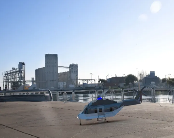
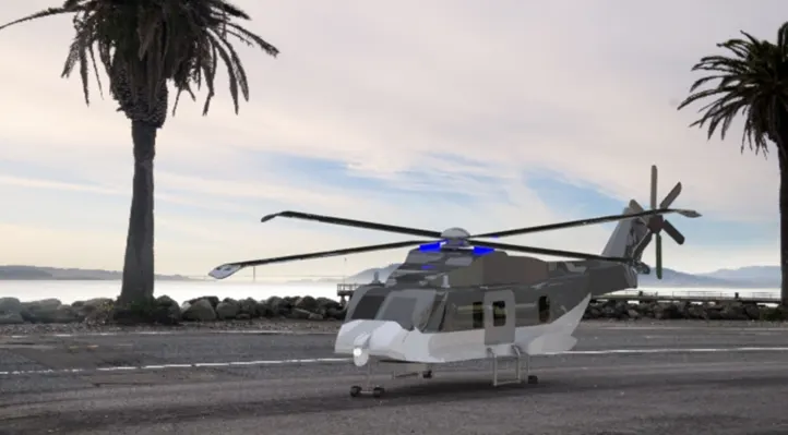
- This helicopter was designed interior and exterior rendered by photo rendered 360°.
IDEATION.
- Selection of project: - this Project was selected due to the flow of air in aerodynamic flow in this structure, process has selection of design, or an object by the complication.
- Management of time: -in this process I had divided the time for designing different parts, object has to complete within time, example: - designing the car part by part & designing the complicated car cannot be completed by date.
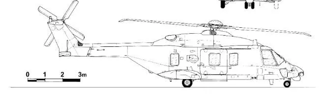
- Blueprint selection: blue print selection is the main selection approved like getting the suitable blueprint which I am capable of and other inputs
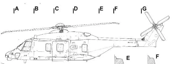 mid plane
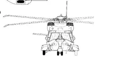 front view
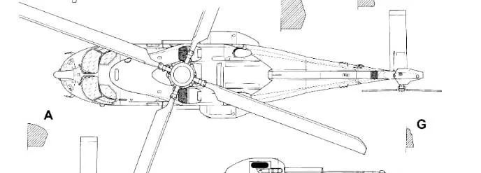 top view
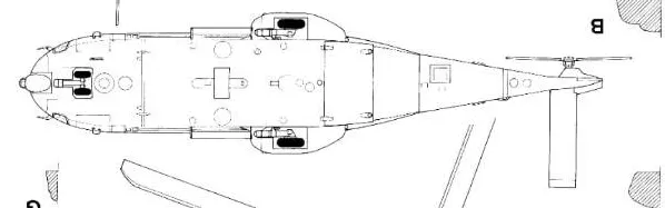 back view
 inverse of mid view
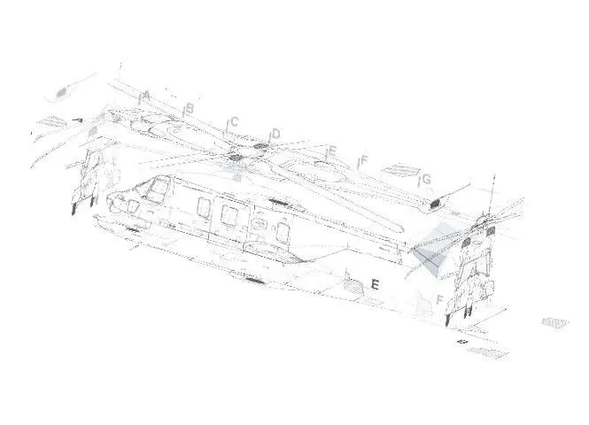 isometric view
METHODOLOGY.
- Creating sketches and composite curves: - I have taken the base view of helicopter as reference, I had created sketch and some sketches is converted as curve and composite curve.
Some of the sketching entities:
- Line: the primary object is the line. a series of connected straight line segments can be drawn by invoking the line command and then selecting the proper sequence of endpoints, starting a point with two end point connected with direction path. with 2 direction and 3direction sketch.
- Rectangle: in this step there are 4 types namely
1.corner rectangle
2.center rectangle
3.3-point corner rectangle
4.3-point center rectangle
1.corner rectangle: - specify a point to define the opposite corner of the rectangle with dimension with 2 point.
2.center rectangle: - specify a point to define the center point and the opposite corner of the rectangle with dimension with 2points.
- 3-point corner rectangle: - specify a point to define the opposite corner of the rectangle with dimension with 3points.
- 3-point center rectangle: - specify a point to define the center point and the opposite corner of the rectangle with dimension with 3points.
- Circle: -in this sketch we have two points center circle and perimeter circle.
Circle is the two-point arc covered of 360°.
Center circle: is one were the center point is fixed the radius is been increased or decreased.
Perimeter circle: this is circle were 3 point of circle were the 3 point are tangent to the circle the circle has fixed radius.
- Spline: - the spline command is used to draw a curve a curve through or near points in a series the type of curve is a nonuniform rational, this type of curve with irregularly varying radii, such as topographical contour lines.
- Slot: this is slot has 4 different types
straight slot
CenterPoint straight slot
3-point arc slot
CenterPoint arc slot
This slot has different types the slot will be of 2-circle binded of two lines it has key slot.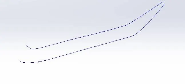
- Creating surfaces: - means taking pair of curves or the sketches and I had constructed a surface by making the constrains as fully constrained, by maintaining the constrains and we can make it as a smooth surface.
These are process
- Extruded surface: - it is the step were the surface is created through extruding the surface by selecting related sketches.
- Revolved surface: -in this step if the sketch of closed surface only the revolved surface is constructed and central axis must be there or it might get an error.
- Sweep surface: -in this step I need to have closed curve and guide curve in surface.
- Lofted surface: - in this step I need to have more curve more than 2 curve, and the guide curve.
- Boundary surface and filled surface: -these steps have same operation of curve but it has connected curve.
- Offset surface: -in this option the sheet is offseted to curtain distance, based on the surface structure.
- Ruled surface & extend surface: - this option is similar to the extruded surface, were the surface extruded it can be extruded in any direction.
- Knitted surface: -in this option the surface is separate then the surfaces is stitched together then the is turned black, or it is undefined so rectified.
- Trimmed surface: - if the surface has extra surface then this option will trim extra surface.
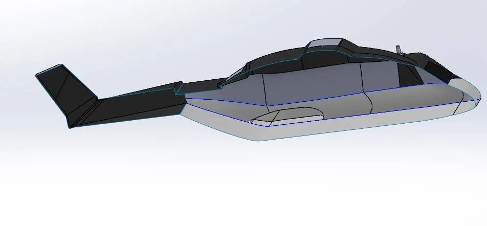
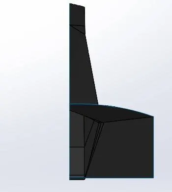
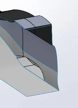
- Converting surface into solid: -this means converting surface to solid is not a matter but while constructing surface if its not properly constructed or knitting properly then the further step will be difficult, there we have to check the minute deviation and correct it , later after building solid its easy to make rails and smaller parts.

- creating sub assembly parts:-I had taken the surface at that location were the sub assembly parts has to be installed later on, I had constructed the components using the reference of the blue print.
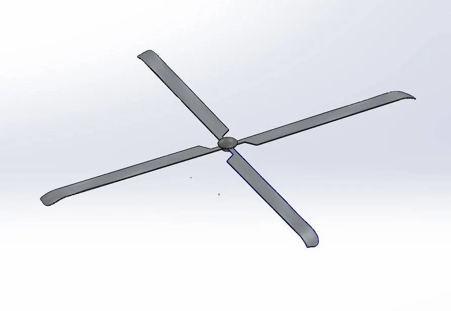 rotar blades
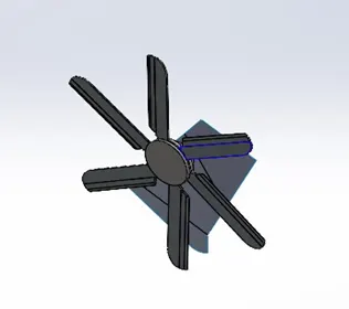 rotational blades
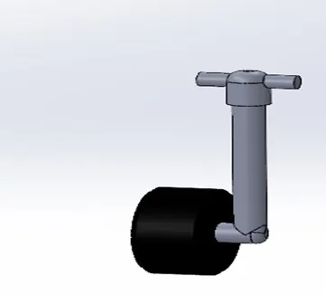 supporting wheels
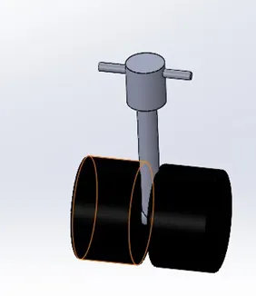 main standard wheels
ASSEMBLY OVERVIEW.
- assembly of part solid with constrains: - the solid parts created before is assembled by constrains no matter any part based on there working structure it’s going to constrain, or if it constrains normally its well and good.
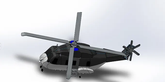
PHOTO RENDERING EFFECT.
- Rendering: - after the final assembly we have to render the project based on colours and also the placing the object into rendered place using photoshop 360°
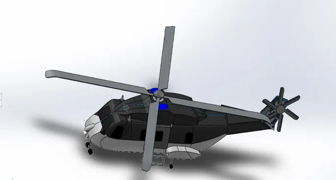
Reference: -
Conclusion: - the interior design & modeling of helicopter has efficient space for transportation of food and medicine, the helicopter flies high greater Hight with broader blades, and the photo rendering is performed delight manner, the modelling is completed as per blueprint and also, I have tried render the helicopter model.