Week 2 Bevel Gear Challenge
Aim :
To analyze and compare the results for the given different mesh sizes of the same material using ANSYS software.
OBJECTIVE
- To describe the Grid Dependency test and its uses
- To perform Static Structural analysis on a Bevel Gear in ANSYS Workbench and perform Grid dependency test with three different mesh sizes
- Case 1: 6 mm as the element mesh size
- Case 2: 5 mm as the element mesh size
- Case 3: 4 mm as the element mesh size
Compare the results of Von-Mises stress, Total deformation, and Equivalent Elastic Strain for three different cases.
1. GRID DEPENDENCY TEST:
The CAD model is divided into smaller regions known as elements using the finite element mesh, across which a set of equations is solved. These equations use a series of polynomial functions defined over each element to roughly describe the relevant governing equation. The calculated solution will become closer to the actual solution when these components are reduced in size and the mesh is improved. The finite element mesh being utilized directly affects the accuracy that may be produced from any FEA model. For FE investigations, mesh refinement is a crucial component in coming up with an appropriate answer. Mesh refinement, in its most basic form, is the process of resolving the model using pr
ogressively finer meshes.
Mesh Refinement is also called a Grid Independent Test.
After comparing a set of solutions, the asymptotic behavior of the solution starts to emerge, and the changes in the solution between meshes become smaller. Eventually, these changes will be small enough that we can consider the model to be converged.
Different Mesh Refinement Techniques
· Reducing the Element Size
· Increasing the Element Order
· Global Adaptive Mesh Refinement
· Local Adaptive Mesh Refinement
So, the grid dependency test helps in determining optimal mesh size where the accurate result could be obtained while keeping in mind the cost of time and power. Since the results obtained are approximate. Refining mesh further would result in negligible percent change is the result but only increase the computational cost.
- By setting up a simulation with a certain mesh size, running the simulation, and then repeating the simulation with a finer mesh size, the grid dependence test is carried out. The procedure is repeated until the outcomes converge and don't significantly alter with additional mesh refining.
- The right mesh size for the simulation is then decided by comparing the results. The mesh size has to be further improved if the outcomes show noticeable differences with each mesh refinement. On the other hand, the mesh size can be seen to be suitable for the simulation if the results do not noticeably change with additional refining.
- The grid dependency test plays an important role since the quality of the mesh utilized determines how accurate a simulation will be. While a mesh that is too fine might increase simulation durations and computing costs without significantly improving accuracy, a mesh that is too coarse can provide incorrect results. Consequently, the grid dependence test aids in determining the ideal mesh size to strike a compromise between precision and computing efficiency.
Basics of Bevel gears:
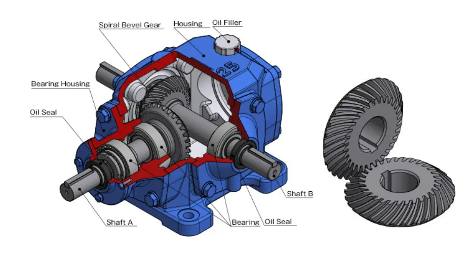
Bevel gears are used to connect shafts whose axes lie at an angle to each other, although in most applications the shafts are at right angles. The tooth profile is basically the same as used for spur gears except that the tooth gets progressively smaller as it approaches the apex of the projected cone. Generally, the shafts of conventional bevel gears intersect, although bevels can be designed to have the pinion offset. When such a pinion has radial teeth, the crown wheel will also have straight teeth but offset in relation to the axis.
- A variation is the hypoid, where the teeth on both gears are cut on the skew in which situation they will act similarly to helical gears with consequent smoother running.
- The spiroid gear has curved teeth and, in many cases, can be likened to an offset worm drive. These systems do, however, cause higher tooth pressures and, as a result, it is important that efficient lubrication is provided.
- Bevel gears are used in differential drives, which can transmit power to two axles spinning at different speeds, such as those on a cornering automobile. Bevel gears are used as the main mechanism for a hand drill.
- When the two gear axes cross, bevel gears are employed to transfer rotational motion at a straight angle. As a result, this kind of gear is frequently constructed symmetrically. Two bevels roll rather than slide throughout the action.
There are several types of bevel gears, including straight bevel gears, spiral bevel gears, and hypoid gears. Straight bevel gears have straight teeth that are cut at an angle to the gear's axis. Spiral bevel gears have curved teeth that gradually transition from one end of the gear to the other. Hypoid gears have a complex curved shape that allows them to transmit power between non-intersecting shafts. Bevel gears are designed to operate at specific angles and speeds and must be carefully selected and installed to ensure optimal performance and reliability in a given application.
3D MODEL SET UP: -
Insert the given geometry
- We start our work by Open Static Structural and in SpaceClaim, import geometry named “Skill_Lync_Bevel_Gear.igs”.
- After importing geometry, we can see unwanted volume in gear. So, remove it with the help of the “PULL” option as shown below.
- For static structural analysis, the provided 3D model of a bevel gear is loaded into ANSYS Workbench. The Small gear has 16 teeth, whereas the Big gear has 24. The regions with little bearing on the analysis results are deleted using SpaceClaim to simplify the provided 3D model for analysis purposes, as indicated.
- After opening the model in SpaceClaim, edit the model by removing the unwanted extra surface which is not required for the simulation process by cutting down a circle with dia. 45mm for the big gear and another circle with dia. 25mm for the small gear.
BEFORE
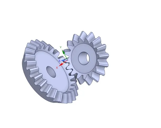
- Geometry modification is done by using Ansys spaceclaim software.
PROCEDURE:
- Get static structure from the analysis system.
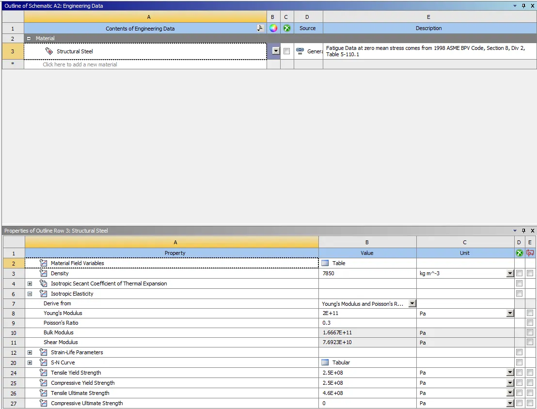
- In Engineering data select Granta Sample Materials.
- From the material list, add material Structural steel as per case to be analyzed.
Open the model in Design Modeler
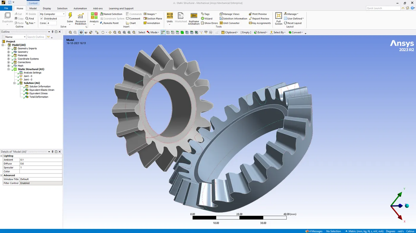
- Rename the Gears as Big and Small Gears and Assign the material.
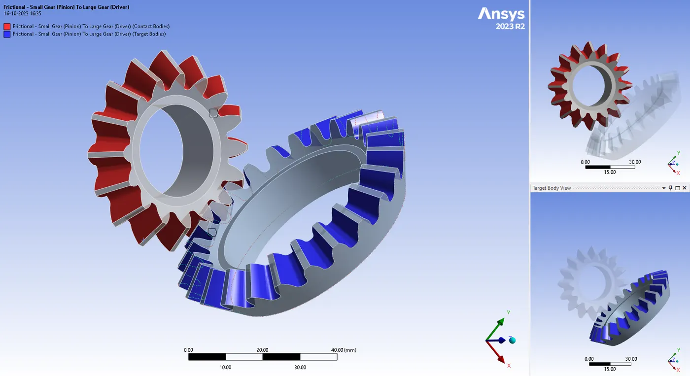
- Contacts are established between the small gear and the big gear.
- Contact Type is defined as Frictional.
- The mating surfaces of the Gears are selected as Contact and Target. The small gear is selected as the Contact Body and the big gear is selected as the Target body.
- Behavior is defined as Symmetric.
- Formulation Type used in Augmented Lagrange. (Augmented Lagrange formulation is chosen because contact penetration is more controlled and can be used for any type of contact.)
- Interface Treatment is changed to Adjust to Touch. (Interface treatment is enabled as adjust to touch because the program ignores any initial gaps or penetration between the contact surfaces and creates an initial stress-free state)
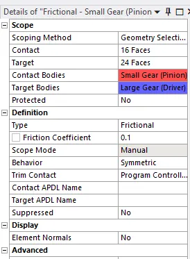
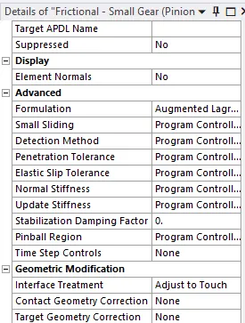
After the connections have been assigned to the Gear structures we move forward to assign the Joints to both gears:
- Joint loads are applied to the gears once the analysis setting has been established.
- Large Gear receives a continuous Moment Joint Load, whereas Small Gear receives a Revolution Join Load for six steps.
Joints
Joints: Joint 1
- Connection Type: Body-Ground
- Type: Revolute
- Body: Biger Bevel Gear
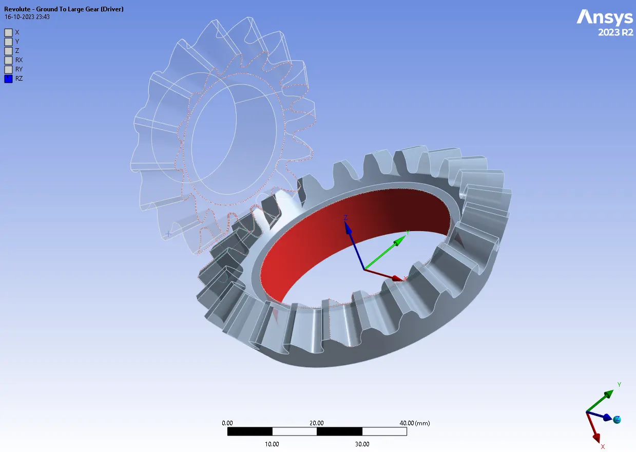
Joint 2
- Connection Type: Body-Ground
- Type: Revolute
- Body: Small Bevel Gear
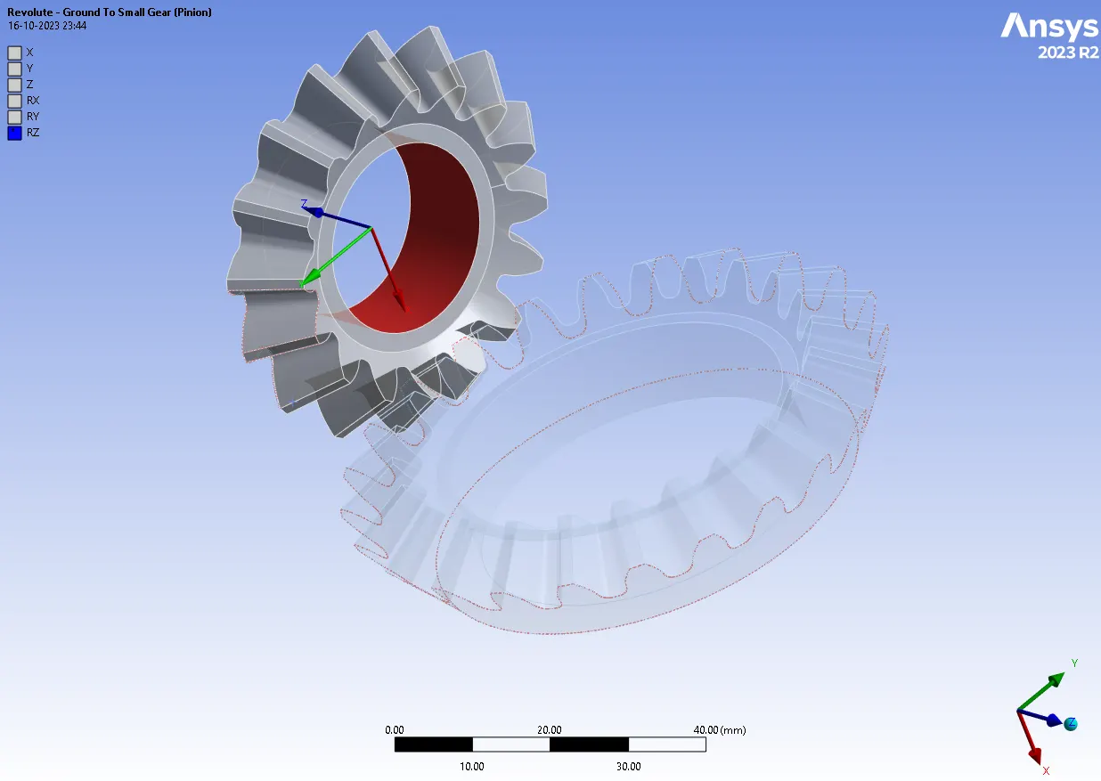
- *Scope=Select the inner portion of the respective gear
- **Make sure that the gears are rotating in opposite directions. If the gears are found to be rotating in the same direction, change the direction of rotation of either one of the gears by changing the Reference Coordinate System.
ANALYSIS SETTINGS
Consider the following as the analysis settings.
Here we are going to look at contact forces, traces, and stress developed for the revolution of gear. So for 120 degree angle, In analysis settings give values as given below:
- No. of Steps = 6
- Auto Time stepping = ON
- Defined by = Time
- Initial Time Step = 0.2 s
- Minimum Time Step = 0.005 s
- Maximum Time Step = 1 s
- Select “Large Deflection on”.
- Due to convergence issues, change the Auto Time Stepping to Program controlled.
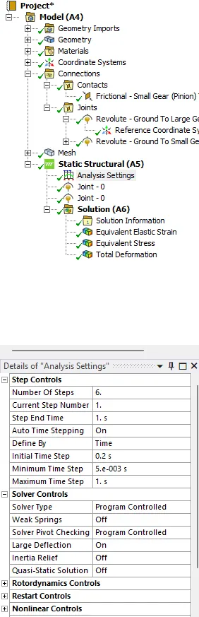
We have faced issues regarding the given time steps explained in the video and after many iterations, this above time step was considered as the best case for the analysis.
JOINT LOADS:
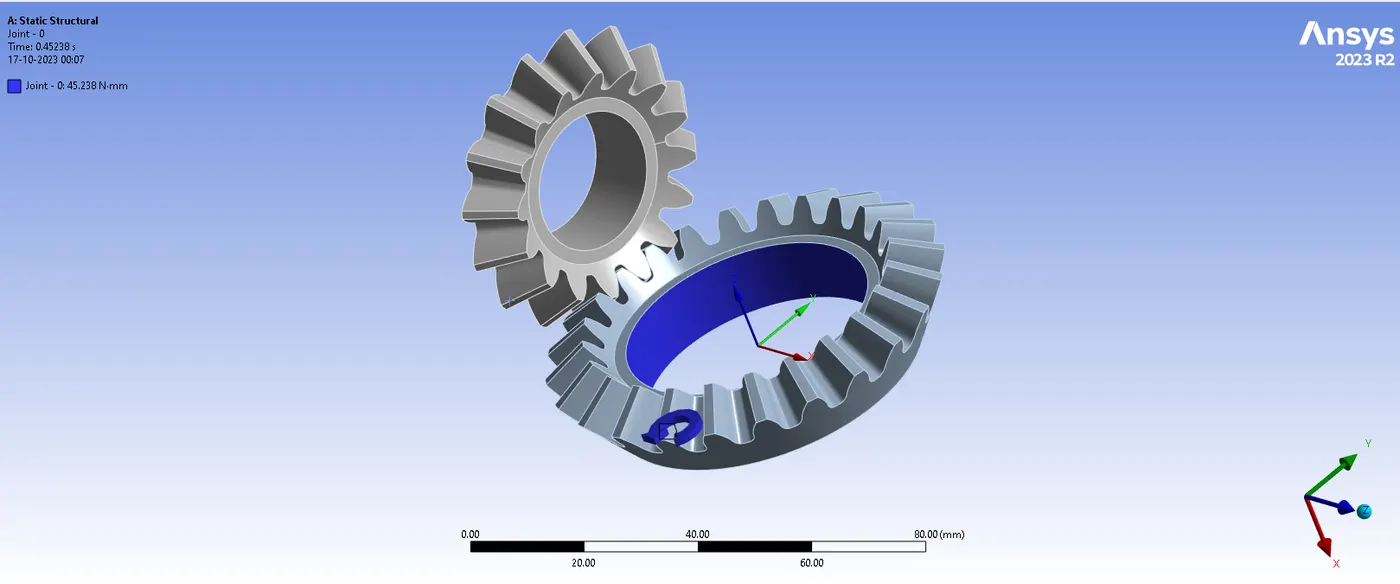
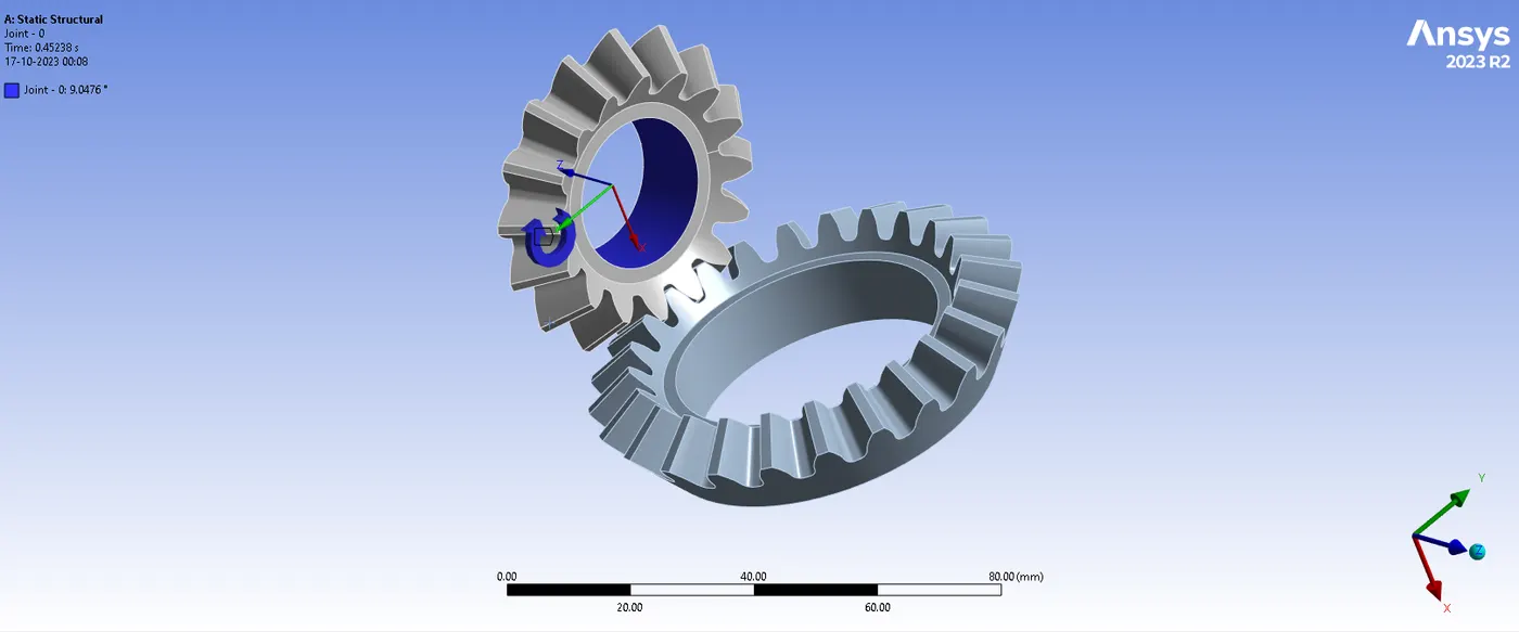
- In static structural, we insert joint load for both the gears in that degree of freedom and magnitude values are added for the rotation of gears.
- To compute the equivalent strain and stress from that, we apply joint loads to the joints, such as rotation for small gears and moment for larger gears. We provide a 100Nm instant. To achieve correct motion between gears, the little gear should spin clockwise, and the big gear ought to rotate counterclockwise.
As we are giving momentum in Big_Gear, consider the following settings for Joint Load for Big_Gear
As we are giving rotation to Small_Gear, consider the following settings for Joint Load for Small_Gear
MESH :
After the Analysis Setup, Generate a Mesh using the default conditions. We can observe that the mesh generated is coarse and needs refinement as it will result in convergence issues.
- To prevent the mesh from being too coarse, we use mesh face sizing. Right-click in Mesh, select Insert, and click on Sizing.
- Select the faces of the gear that come in contact. A Total of 40 faces is observed. Keep the face sizing element size at 1.75mm.
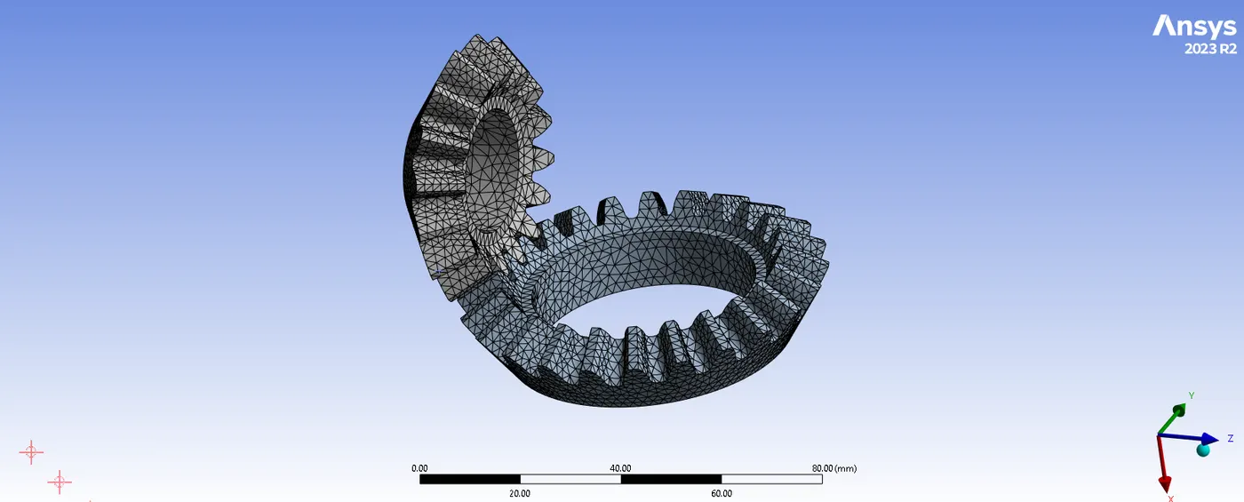
Since each of their teeth will come into contact, we will mesh the gear with a global element size of 6 mm and provide a dimension of 1.75 mm between the teeth before evaluating the result across the teeth.
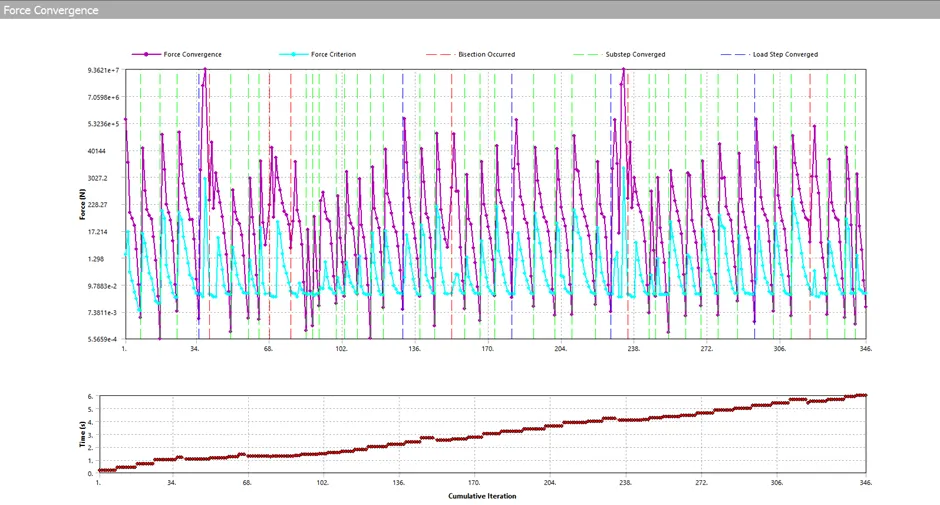
Force Convergence during post-processing
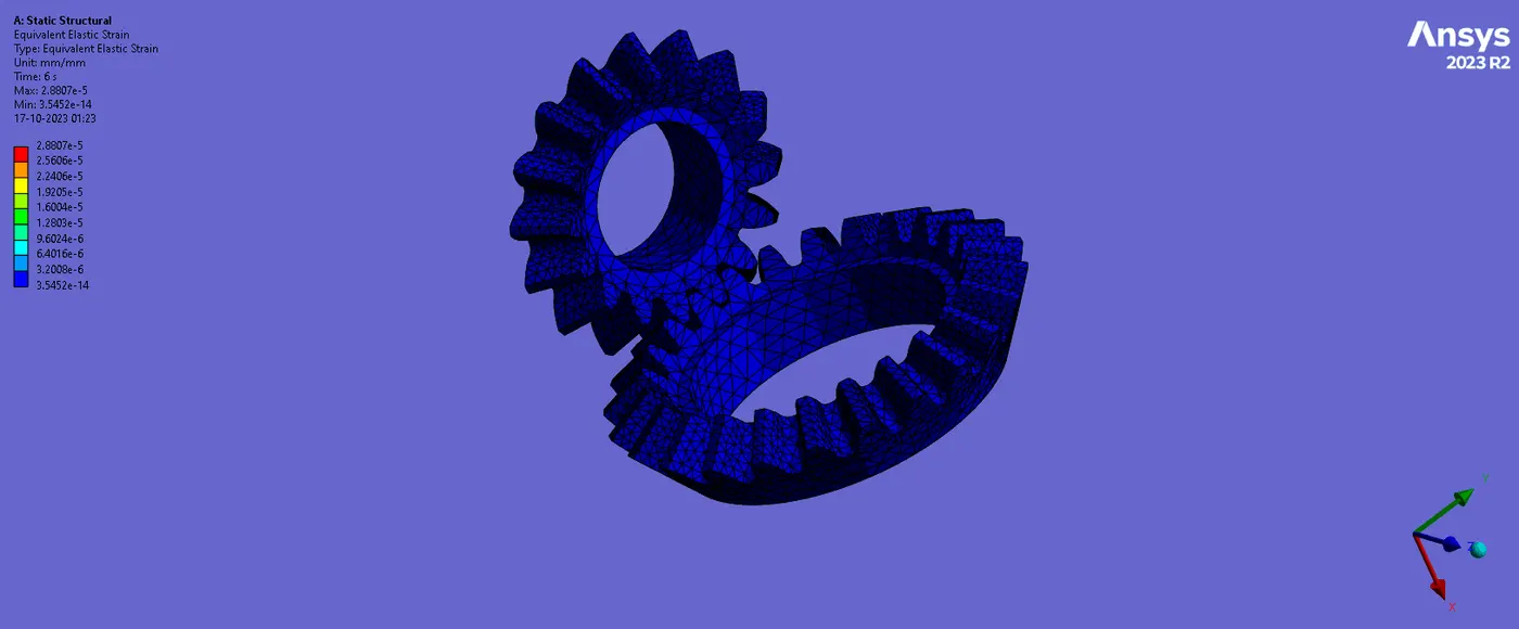
RESULTS CASE 1: Mesh size 4
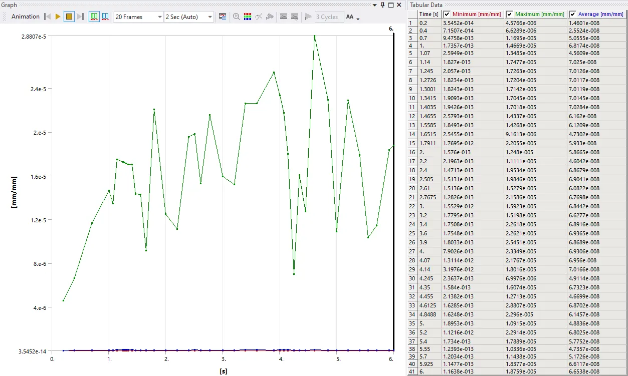
Equivalent Strain
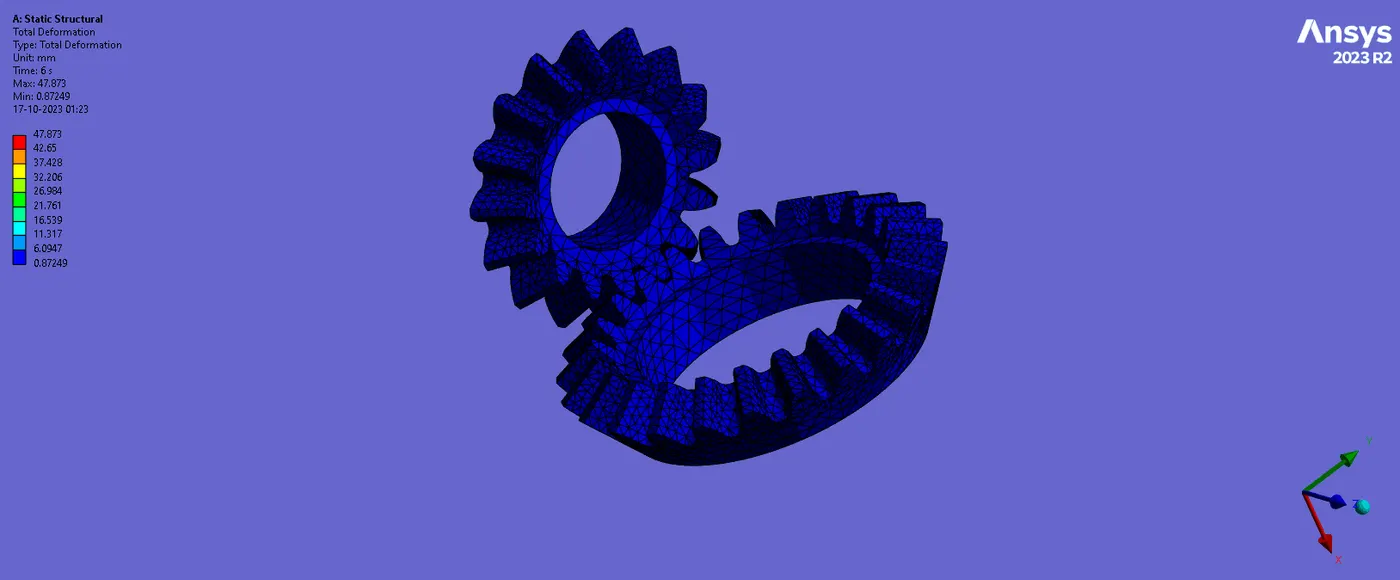
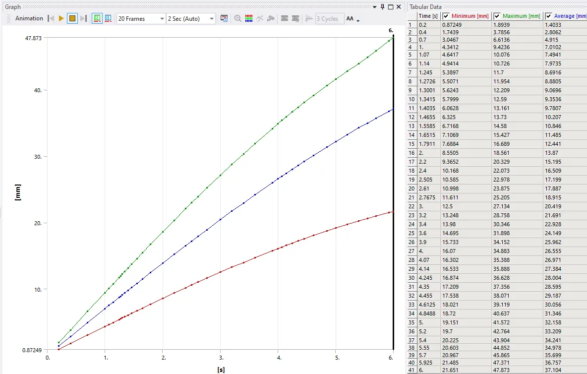
Total Deformation
Equivalent Stress
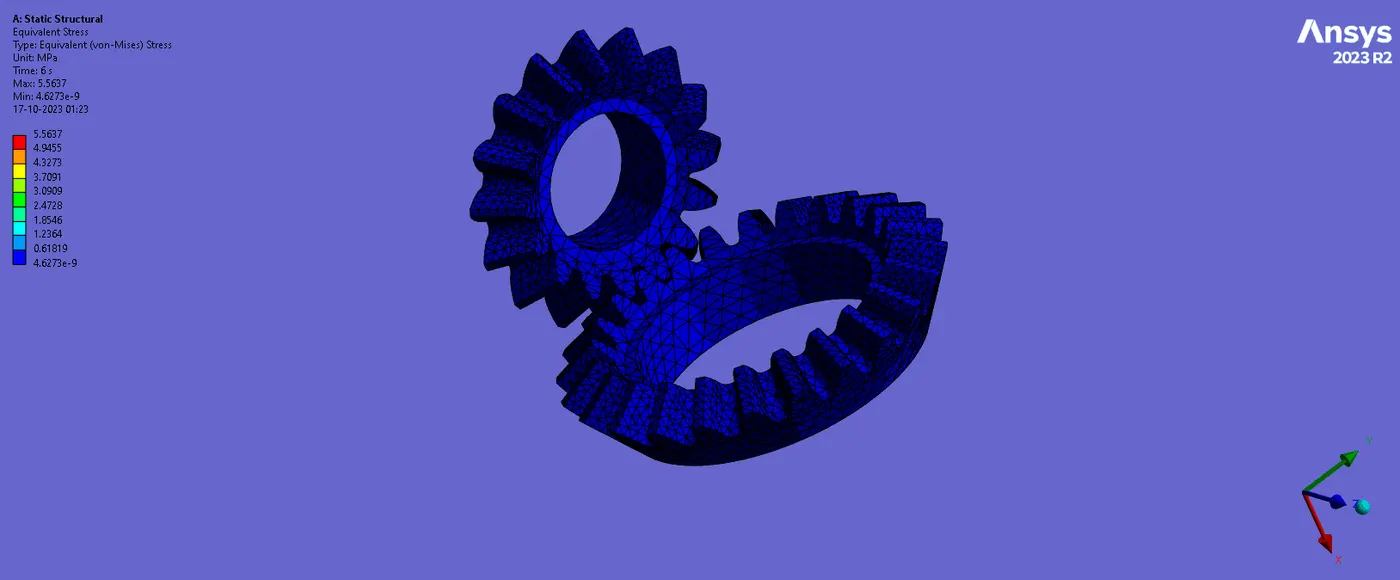
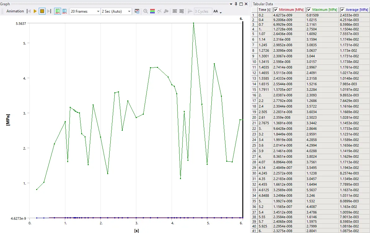
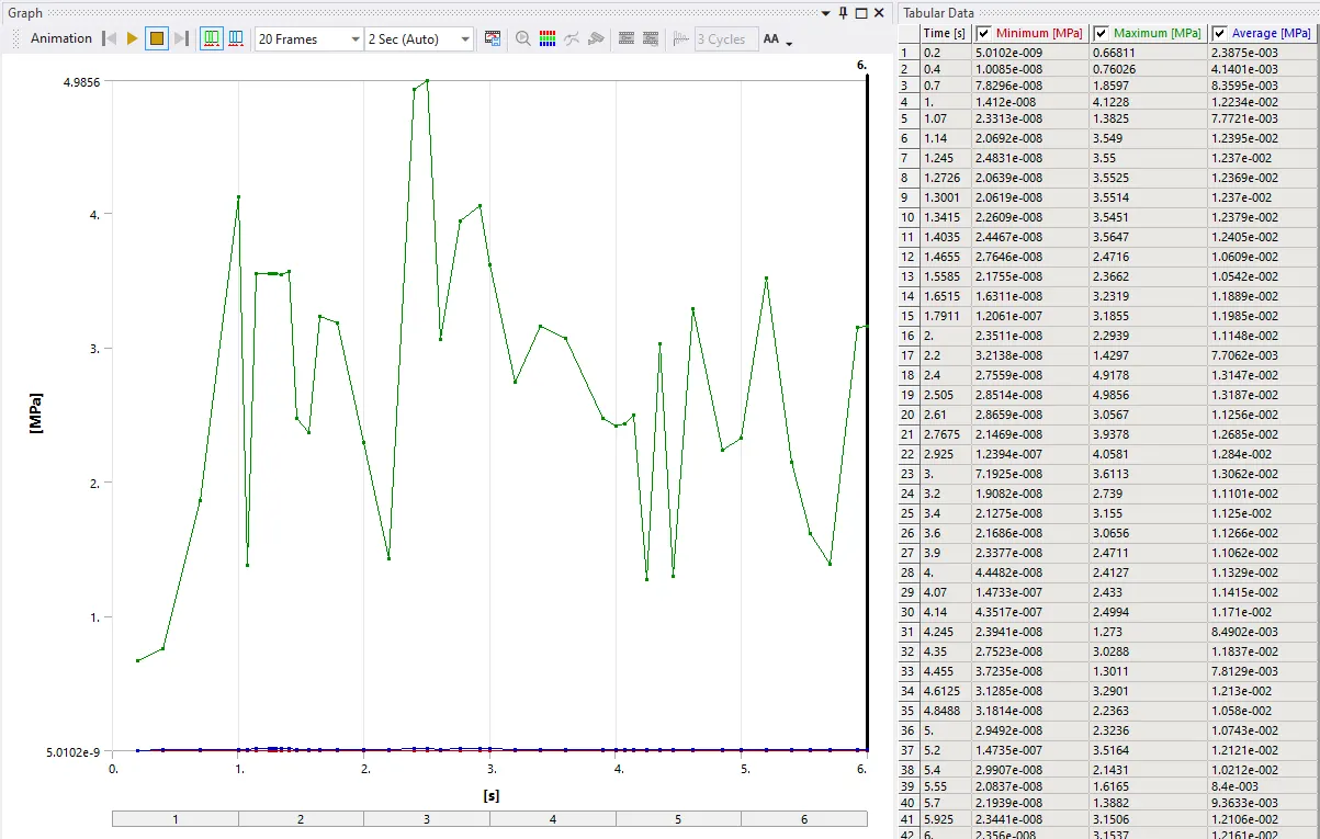
The maximum stress observed was 5.5 Mpa at the juncture of tooths
2. Similarly for Result Case mesh Size- 5mm
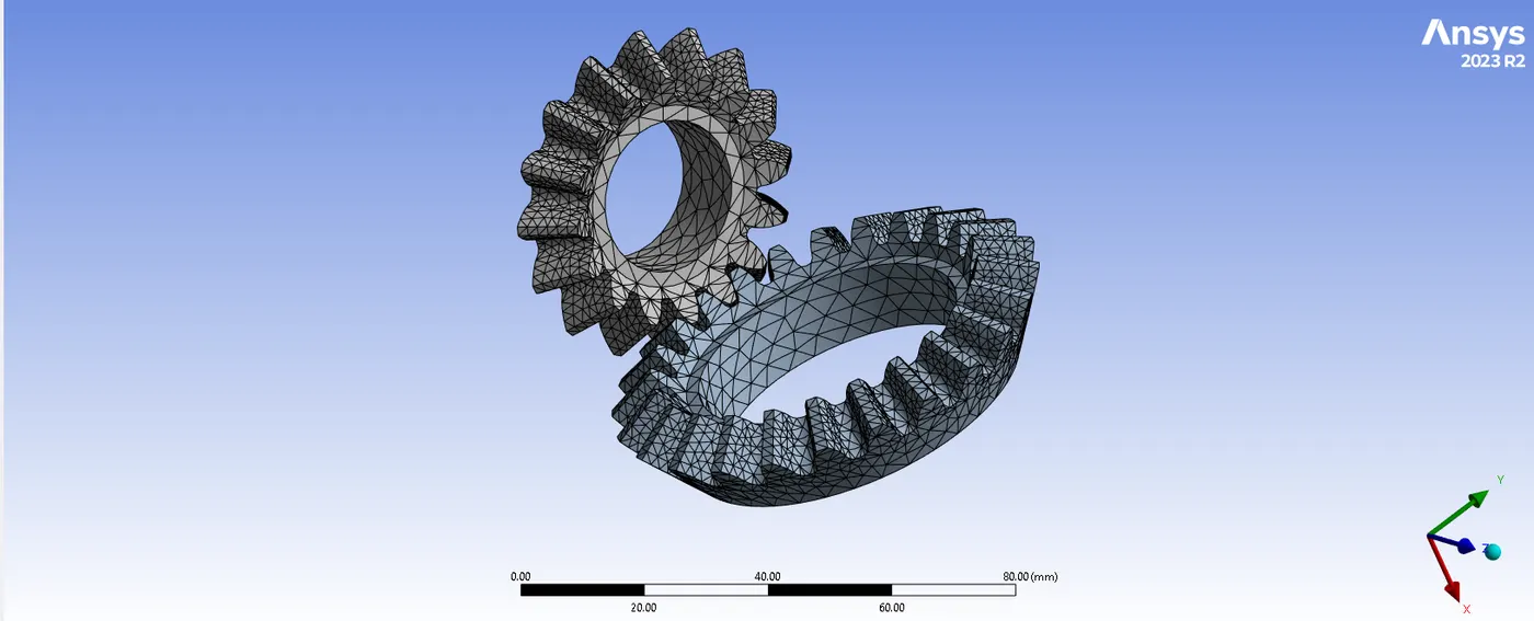
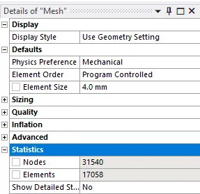
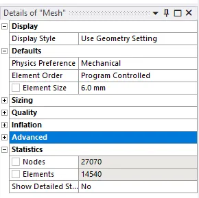
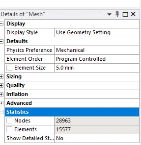 This figure represents the total no of elements and nodes required to mesh the whole system.
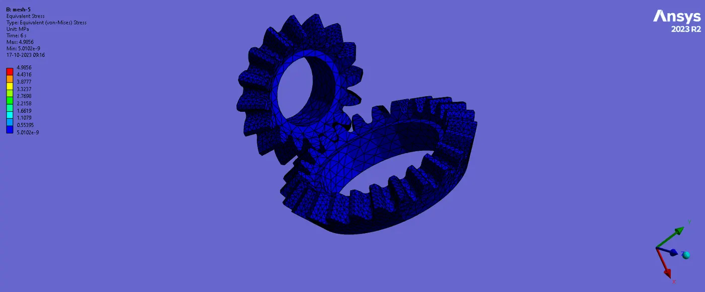
Equivalent Stress
Equivalent Strain
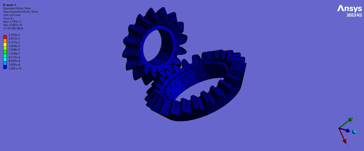
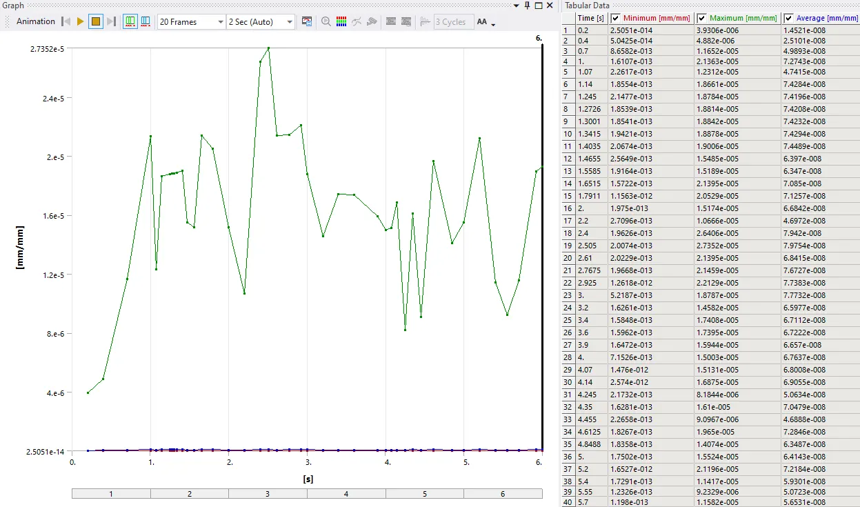
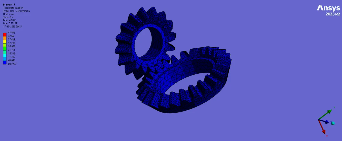
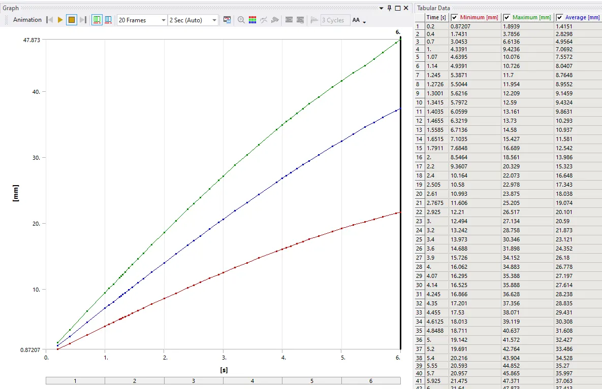
The total deformation for mesh count 5 mm remained the same compared to an earlier case
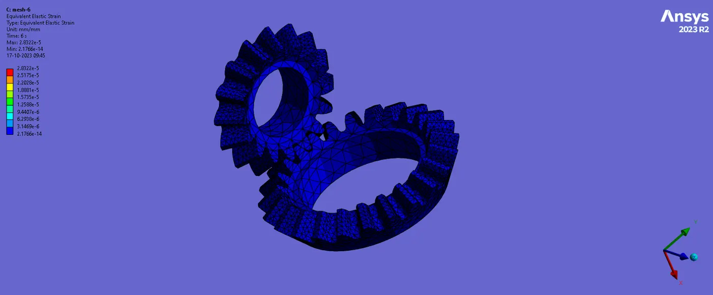
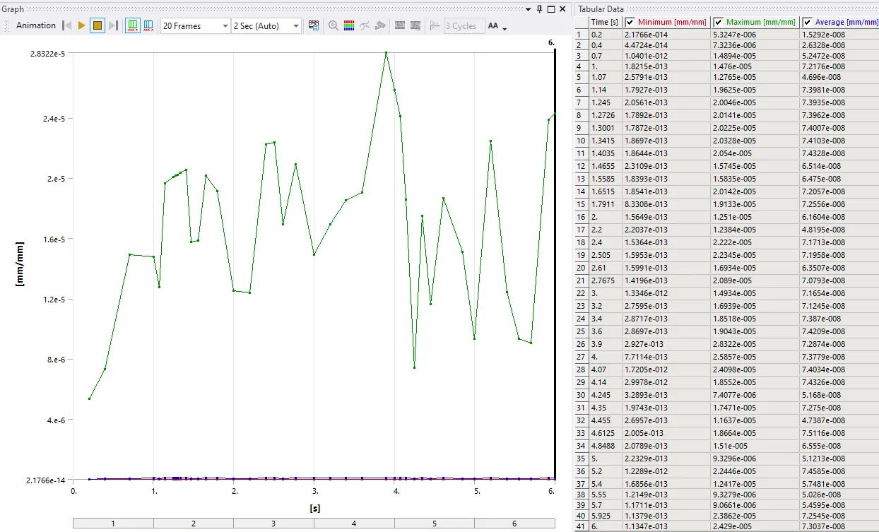
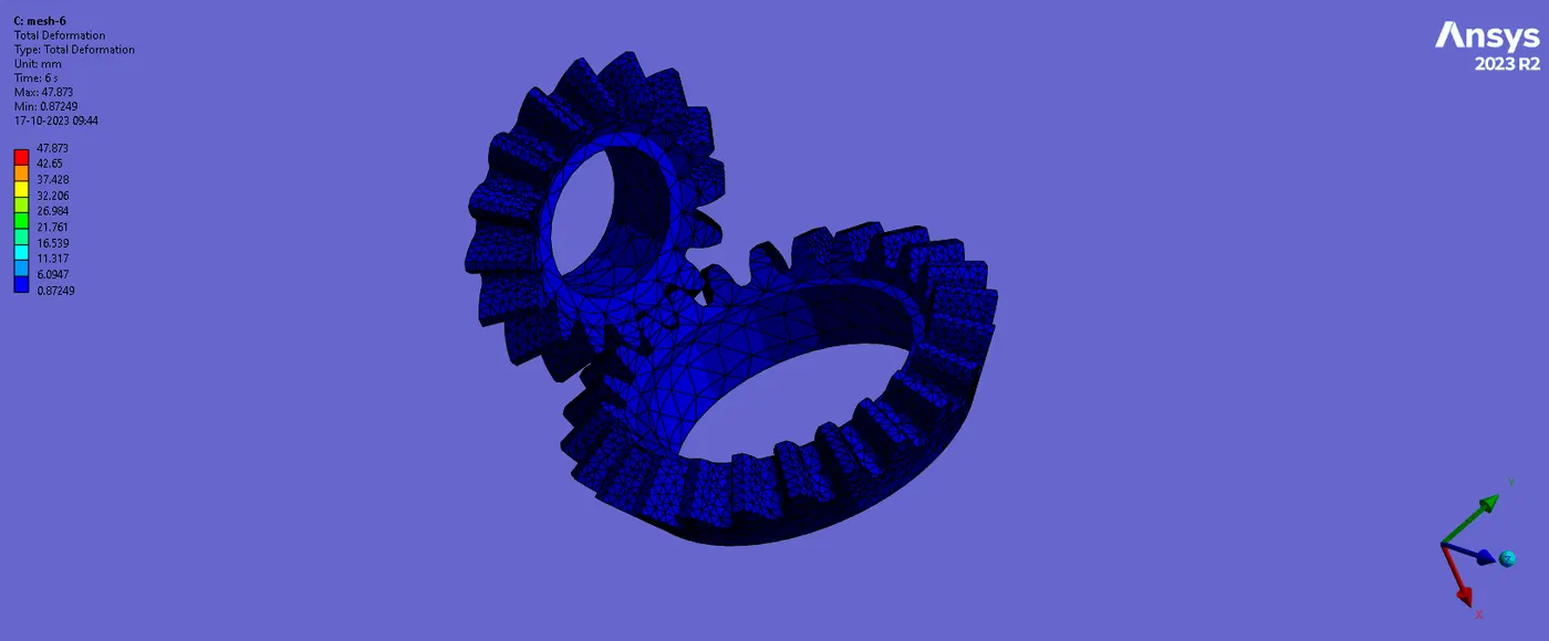
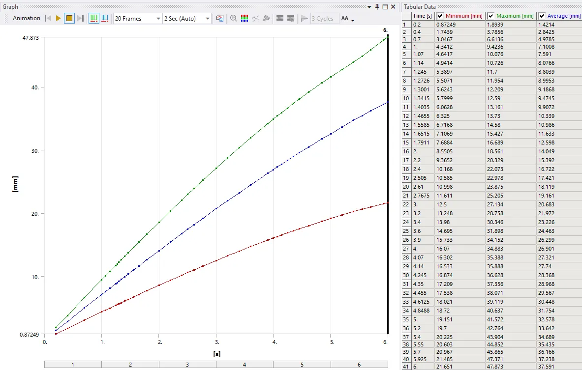
3. Result Case - 6mm
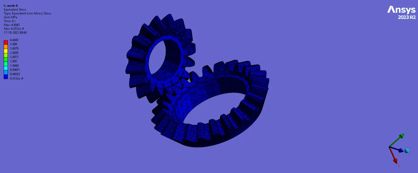
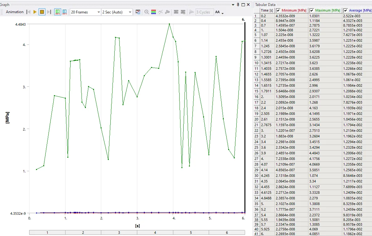
Equivalent Stress:
Equivalent Strain
Total Deformation
- CONCLUSION
The grid dependency test was conducted on bevel gear with different mesh sizes of 6mm, 5mm, and 4mm. The results of each case are tabulated below.
|
|
Von-Mises stress (Max) |
Equivalent elastic strain (Max) |
Total Deformation (Max) |
|
Case 1 – 4`mm |
5.5637 MPa |
2.880e-005 mm/mm |
47.884 mm |
|
Case 2 – 5 mm |
4.9856 MPa |
2.765e-005 mm/mm |
47.88 mm |
|
Case 3 – 6 mm |
4.484 MPa |
2.832e-005 mm/mm |
47.881 mm |
The number of nodes & elements generated in each case are tabulated below
|
|
Case 3 – 6mm |
Case 2 – 5mm |
Case 1 – 4mm |
|
Nodes |
27070 |
28963 |
31540 |
|
Elements |
14540 |
15577 |
17058 |
From the above findings, it has been noted that when mesh size decreases, the number of nodes and elements created rises. More nodes and elements are created when the mesh is smaller which means the discretization is much fine, hence more no of governing equations thus more stiffness as well as the load bearing and distribution is also proper. The findings are more accurate in these cases but the problem is the computational time which henceforth will increase with smaller mesh counts, through grid independent test it is clear that we have to arrive at one optimal mesh size where one can balance the result as well as computational time as we know in industry " Time is Money ", save computational time save money.
In the 3 cases above I believe mesh 5 mm is much more optimized than the 4 mm and 6mm. 6 mm mesh count approximations are abrupt and the values are not reliable whereas 4 mm mesh count has much higher accuracy as well as higher computational time but the difference between the stress values when compared to 4mm and 5mm mesh counts lies within 9% that's between 10 percent of error approximation which is ideally acceptable as well as practically acceptable.
The finest mesh size of 4mm had the greatest equivalent stress and equivalent elastic strain values when comparing each example. Each time, the total amount of change deformation is really little.
Both these cases have higher FOS as well as higher margin of Safety which is much more reliable, thus keeping the design safe.
Summary
A test of grid dependence has been conducted, and We may infer from the above table and plot that when running a grid dependence test on a bevel gear, we can greatly improve the accuracy of the results by changing the global mesh size. As the mesh is refined from 6mm to 5mm and then from 5mm to 4mm, we can see that we get better approximations of the results for equivalent elastic strain and equivalent stress. However, running the simulation with further mesh refinement would produce a very close approximation of the results with a very negligible change in the result and an additional on the computational power and time.
- We can observe from the results obtained from every instance that the percentage difference in stress is smaller in the fine mesh cases.
- The difference in strain is hardly noticeable, In each situation, the overall deformation is the same.
- Because the difference in strain is so small, we can employ a 5 mm mesh because a 4 mm mesh requires more computing time.