Week 3 Sheet metal Bending challenge
AIM:
To perform a static structural analysis on sheet metal bending using three different materials (copper alloy NL, magnesium alloy NL, and aluminum alloy NL) and compare their results in terms of directional deformation, equivalent stress, and equivalent strain. Additionally, play with different frictional coefficient values, fine-tune the mesh, and compare results with aluminum alloy material.
OBJECTIVES:
3 cases are to be simulated which are:
- Case 1: Aluminium Alloy 1199 NL, Copper Alloy NL, and Magnesium Alloy NL materials are used as Workpiece material, and then generated data is compared.
- Case 2: Similar to case 1 Aluminium Alloy is set up, only the coefficient of friction is set to 0.19
- Case 3: Case 1 Aluminium Alloy 1199 NL plate is meshed with more refinement till the academic limit and again the results are compared with case 1 as a mesh dependency study.
THEORY
Sheet Metal Bending:
When sheet metal forming techniques are applied to workpieces with high surface area to thickness ratios, the material's thickness is frequently kept from being decreased to prevent necking and ripping. Sheet metal is bent to increase its stiffness and create the necessary shape for a specific purpose. Bending is a popular procedure used to create structural stampings including angles, channels, hinges, braces, brackets, and supports. It is possible to make pieces by bending in several directions that would otherwise need to be drawn. Bending can occasionally result in various angles, even though it is typically done at a 90° angle. The terms for angle bending and straight bending are shown in the illustration below.
Terminology for straight bending or angle bending.
A bend is achieved by stressing the metal beyond its yield strength, but not exceeding its maximum tensile strength. In bending, a unique distortion takes place as the external surface is stretched and the internal surface is compressed.
Metal Bending.
As illustrated in, the neutral axis of the bend is the location inside the material where there is neither tension nor compression. For thin materials, the neutral axis is assumed to be in the middle of the bend; but for thicker materials, it is located approximately 30% of the material thickness from the inside of the bend.
Bending is primarily done on press brakes, though a stamping die can be used. This equipment may be mechanically or hydraulically operated, similarly, to other metal-forming operations. There are two types of press brake bending operations: air bending and bottom bending as shown below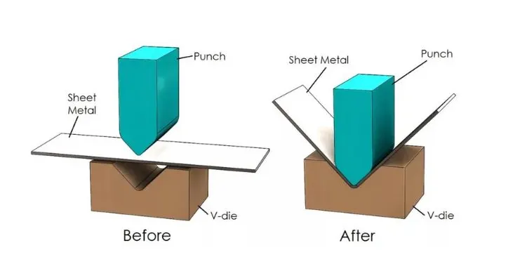
Basic bending methods.
Air bending is the term for bending operations carried out in V-dies when less force is required since the punch does not bottom. When bottom bending, the internal radius is precisely produced and the work is forced all the way into the female die. As a result, continuously precise flange sizes are achievable. Bottom bending has a maximum work thickness restriction because it requires a greater force.
ANALYSIS SETUP
Geometry:
Now import the geometry from the stored location into the project environment.
Double-click to open it in SpaceClaim and check for any topological errors in it.
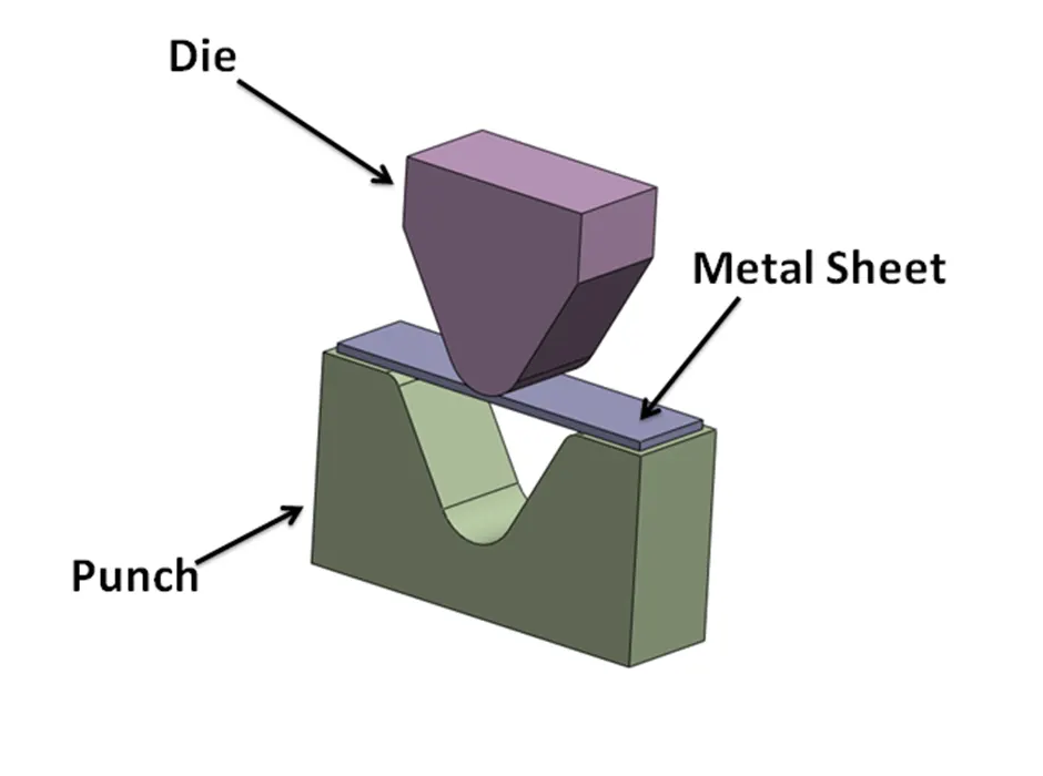
Assign Materials:
- Next, for the Sheet displayed in the Figure below, specify the material as Aluminum Alloy 1199.
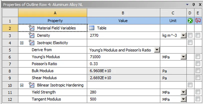
- Define the material for the other two scenarios in a similar manner. The material characteristics are displayed in the Figures below.
- Select a material by clicking the Geometry >>Choose the Sheet. Geometry >> Assignment >> Parameter Window Aluminum-based alloy.
- Here, in the first instance on its own, we must specify three materials for the sheet, such as magnesium alloy, copper alloy, and aluminum alloy 1199.
Material:
CASE:1 {Material - Aluminium Alloy 1199}
- Density: 2770 Kg/m3
- Young’s Modulus: 62000 MPa
- Poisson’s Ratio: 0.33
- Yield Strength: 140 MPa
- Tangent Modulus: 209.46 MPa
CASE:2 {Material - Copper Alloy NL}
- Density: 8300 Kg/m3
- Young’s Modulus: 1.1 E+05 MPa
- Poisson’s Ratio: 0.34
- Yield Strength: 280 MPa
- Tangent Modulus: 1150 MPa
CASE:3 {Material - Magnesium Alloy NL}
- Density: 1800 Kg/m3
- Young’s Modulus: 45000 MPa
- Poisson’s Ratio: 0.35
- Yield Strength: 193 MPa
- Tangent Modulus: 920 MPa
CASE:4 & CASE:5 {Material - Aluminium Alloy}
- Density: 2770 Kg/m3
- Young’s Modulus: 71000 MPa
- Poisson’s Ratio: 0.33
- Tensile Yield Strength: 280 MPa
- Tensile Ultimate Strength: 310 MPa
Now, click on Model and select Edit to launch the Mechanical Module and the load geometry in the module.
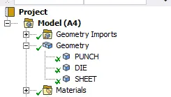
Next, expand the Geometry option and rename the parts in the geometry as shown below:
Define Connections :
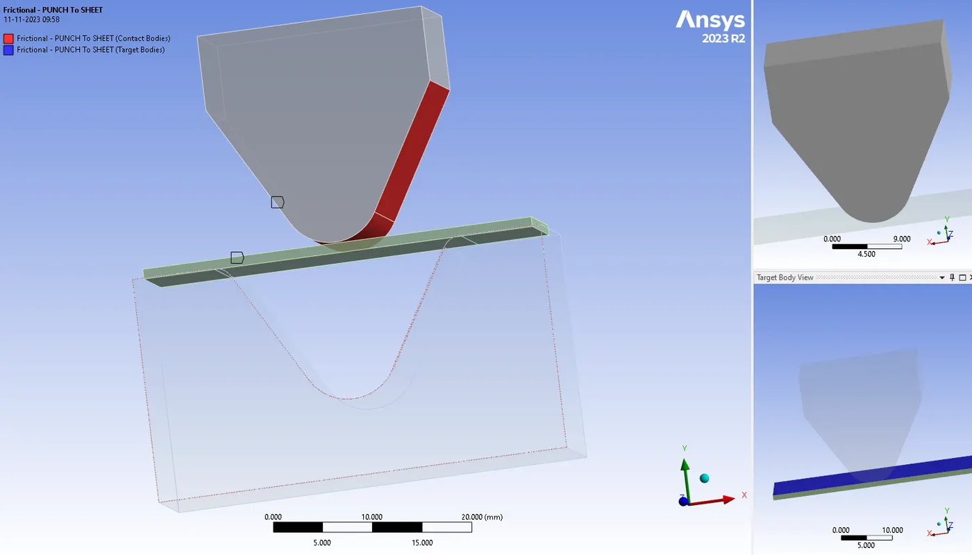
- We have created two contacts, One is between Punch and Sheet and the other one is between Sheet and Die.
- Select the Punch Cone face as Contact and Select the Work Piece (Sheet) Top Face as a Target
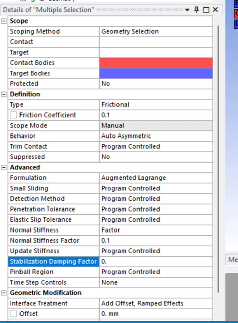
- Contact Type-Frictional with Coefficient of friction-0.1 between the contact faces.
- Behaviour-Auto Asymmetric.
- Formulation-Augmented Lagrange.
- This Algorithm will help to increase the stiffness of the contact and resist the penetration between them.
- Interface treatment-Add Offset, Ramped Effects
-
Note-
- Here for both cases Frictional coefficient is 0.1
- For cases 2 and 3 it is going to be 0.19.
Mesh Details:
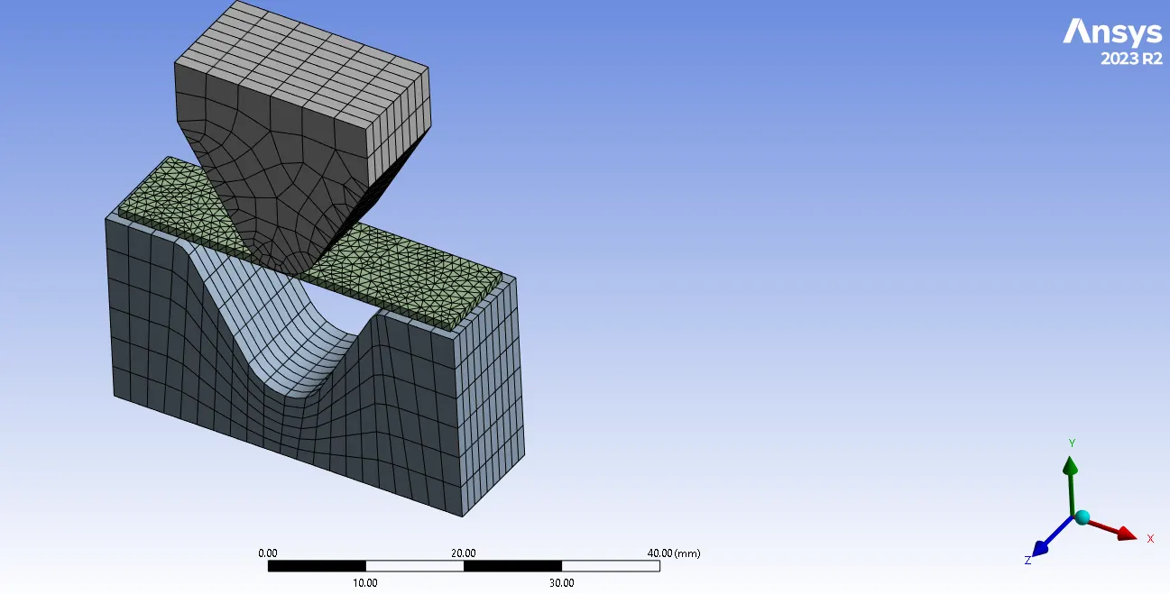
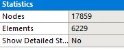
The element size of the punch and die are set as 4 mm using the body sizing option. The element size of sheet metal and contact regions of punch and die are set as 1 mm using the face sizing option. Using the patch conforming method, the element types of sheet metal is set as a tetrahedron. The total number of nodes and elements generated are 17859 and 6229 respectively. For case-3 analysis, the element size of sheet metal and contact regions of punch and die are refined to 0.75 mm.
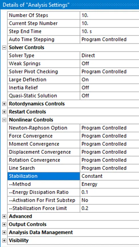
Analysis Settings :
- Here for this Sheet Metal Bending Model, We are giving 10 steps to run simulation.
- Auto Time Stepping-Program Controlled.
- Large Deflection-ON.
- Solver Type-Direct.
- Stabilization -Constant.
- Method-Energy.
- Energy Dissipation Ratio-0.1
Boundary Conditions:
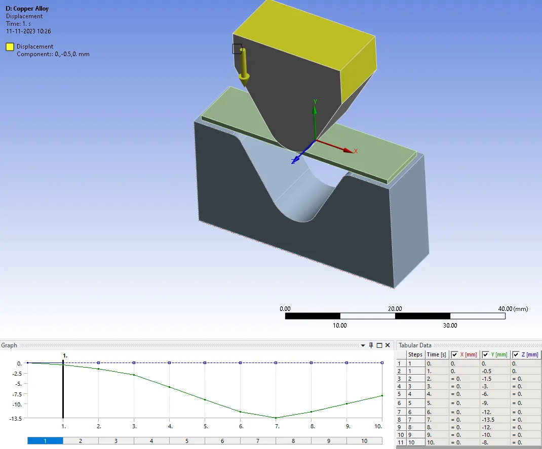
Displacement is given to the punch to bend the workpiece and the die is fixed as shown below.
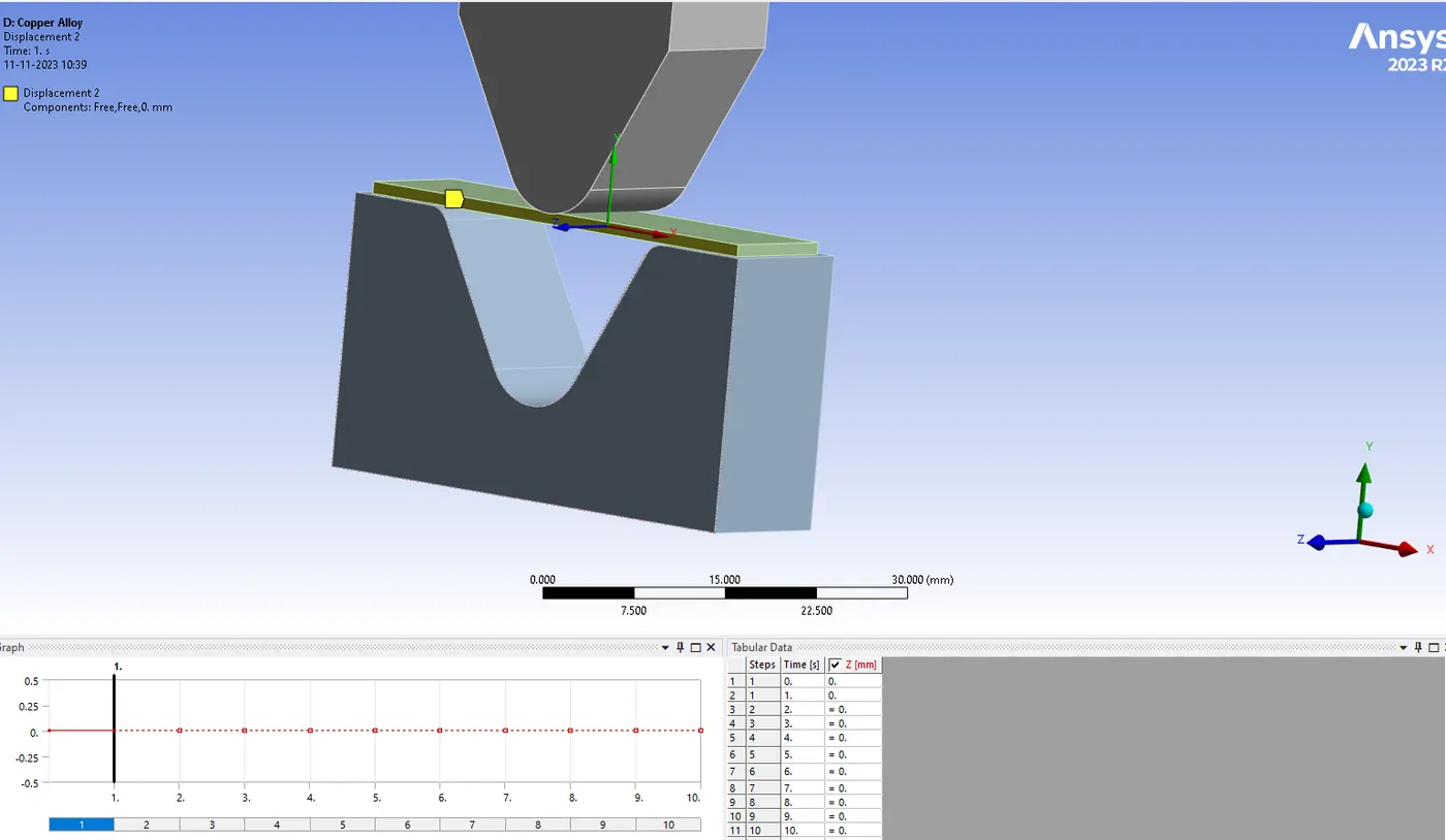
- Now for the plate define the boundary condition as follows, here select the side face of the sheet metal front and back as marked by yellow.
- Now select displacement BC for Punch, here select all five outer faces for BC.
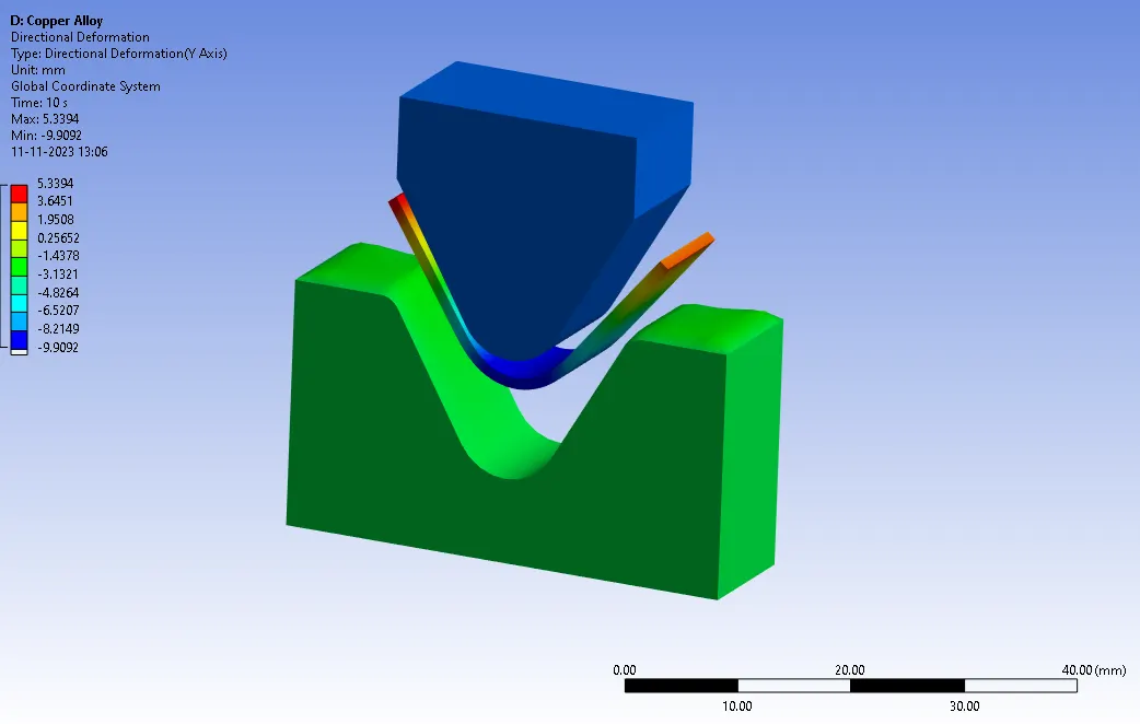
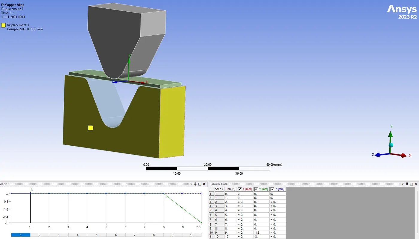 The sheet metal must bend into a V shape due to the displacement provided to the punch. Sheet metal is limited in its lateral mobility during bending. After bending, displacement is delivered in a Y direction to the die's surface in order to disengage it.
Solution-
- Now for stress click on the solution>>insert>>stresses>>equivalent (von Mises).
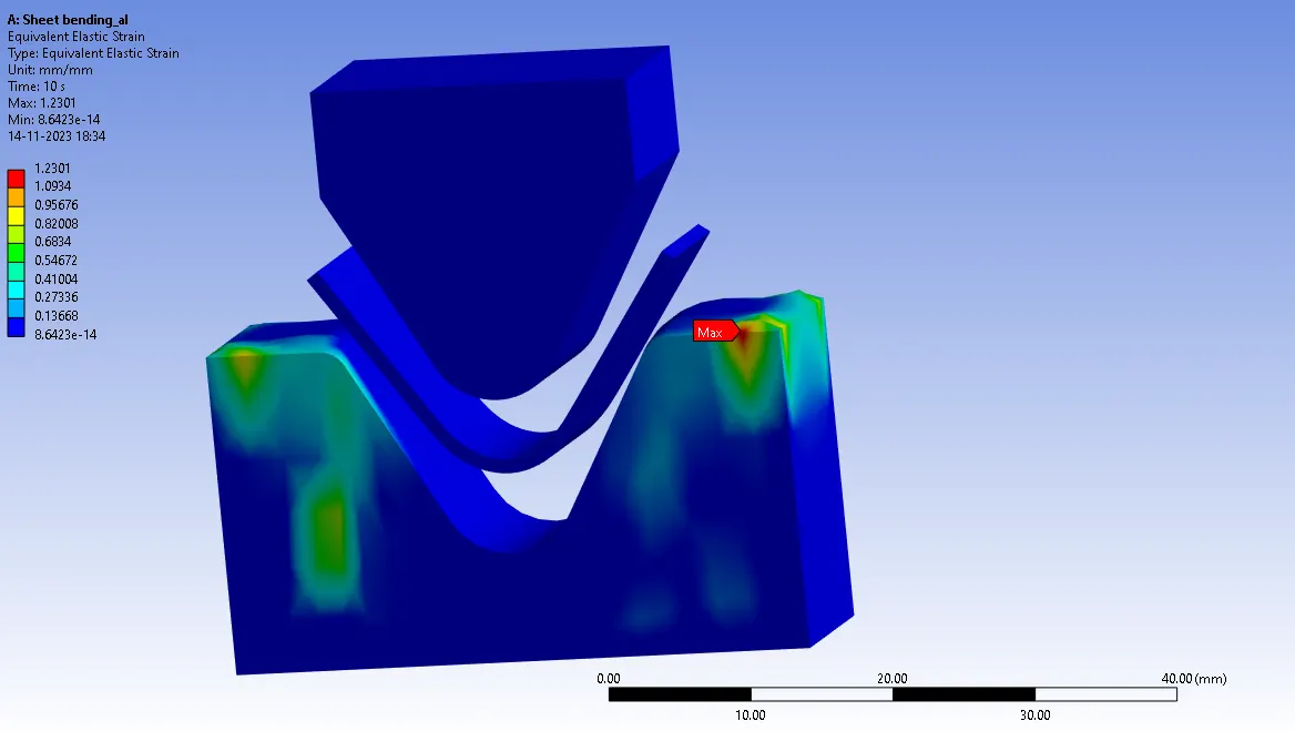
- Now for strain click on the solution>>insert>>strins>>equivalent (von Mises).
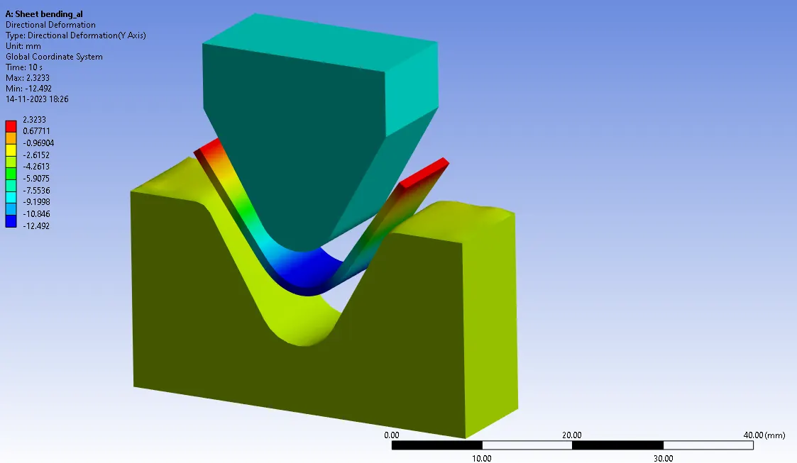
- Here we have to define total deformation, to do so right-click solution>>insert>>deformation>>directional, and select Y-axis.
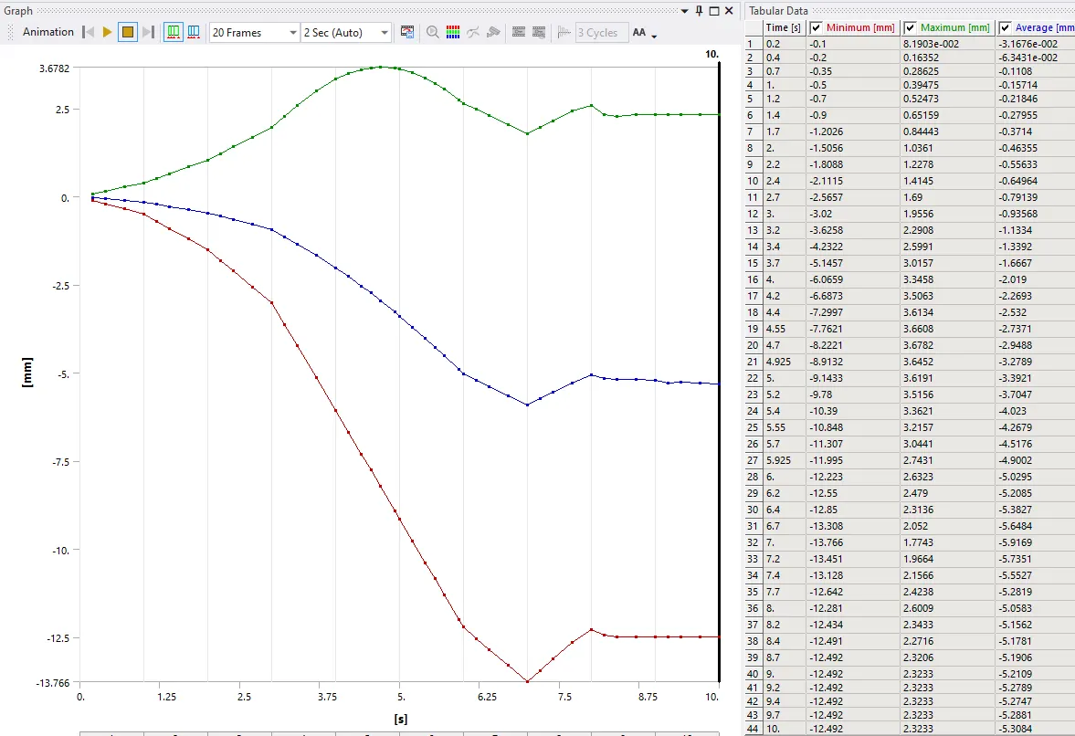
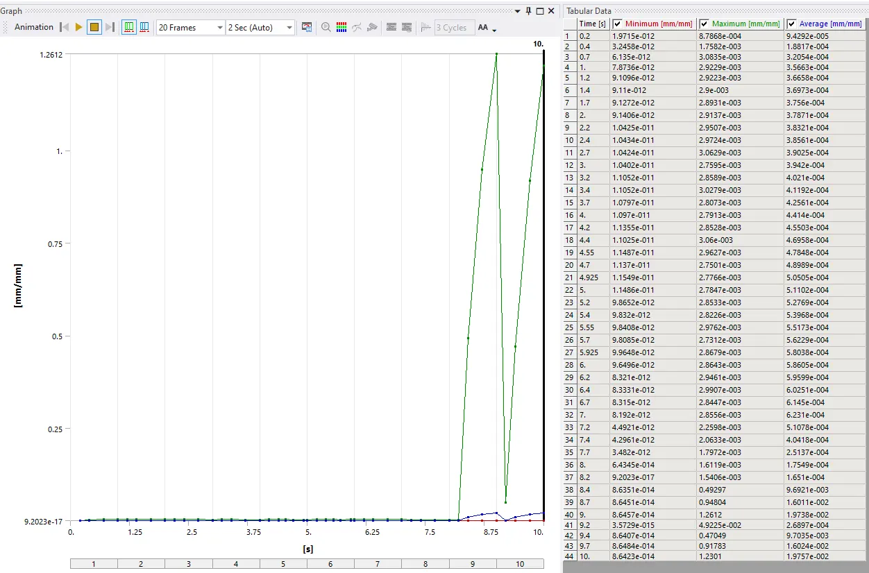
ALUMINIUM ALLOY WITH (Frictional coefficient- 0.1)
DIRECTIONAL DEFORMATION
ELASTIC STRAIN
EQUIVALENT VON-MISES STRESS
ii. COPPER ALLOY
DIRECTIONAL DEFORMATION
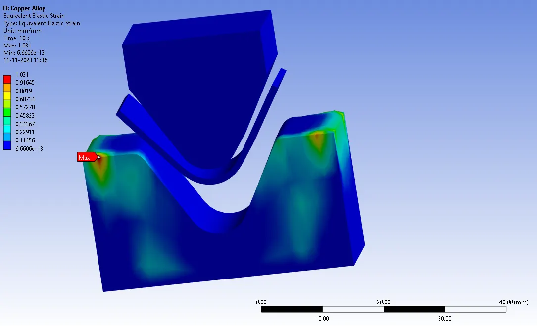
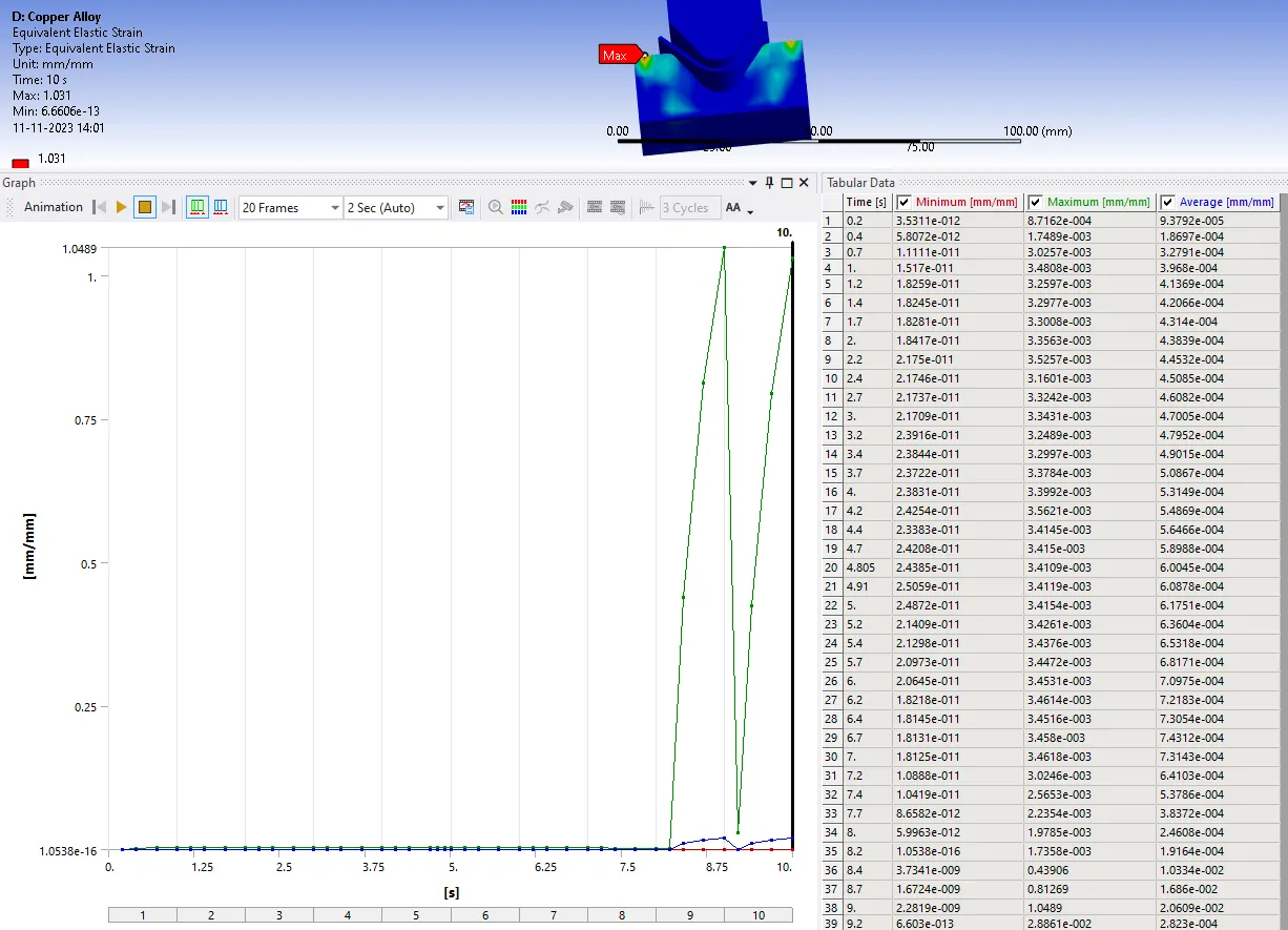
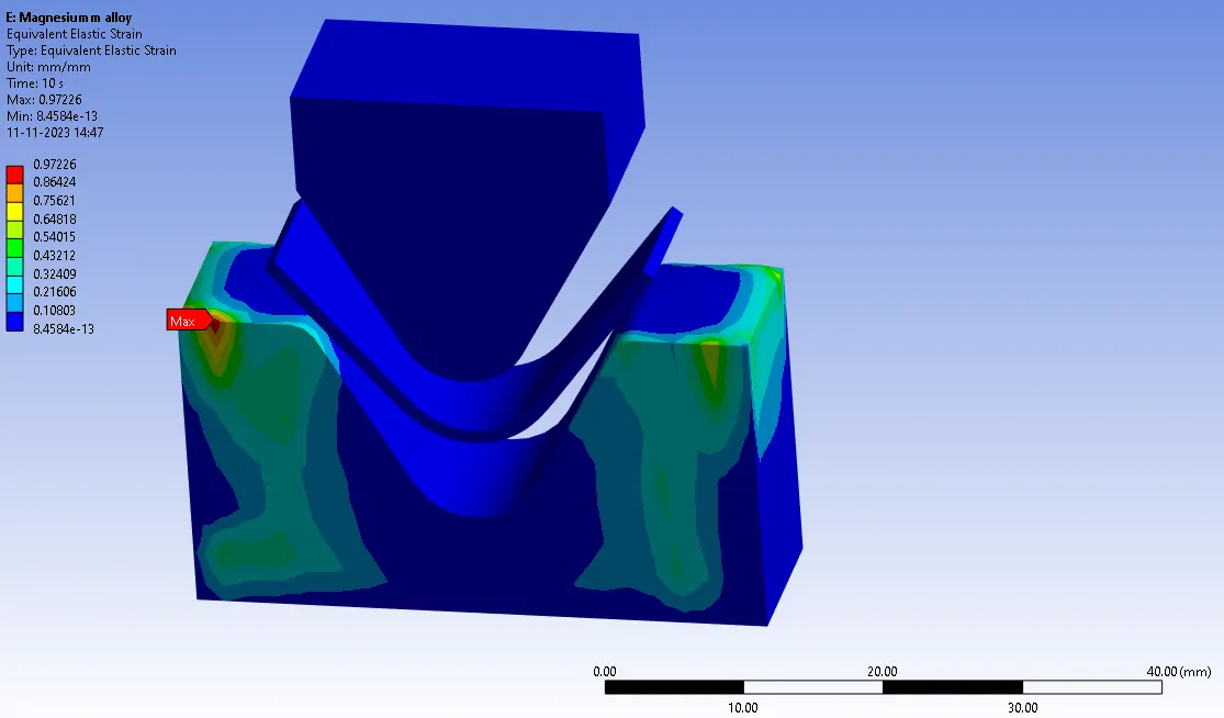
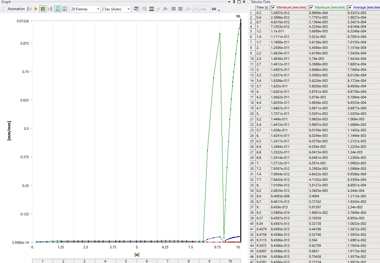
EQUIVALENT STRAINS:
EQUIVALENT VON-MISES STRESS:
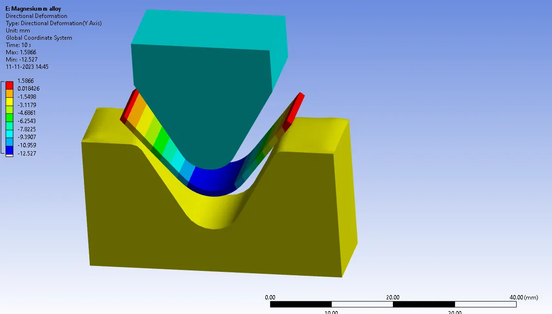
iii. MAGNESIUM ALLOY
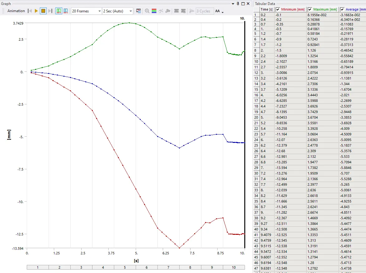
DIRECTIONAL DEFORMATION
EQUIVALENT STRAIN:
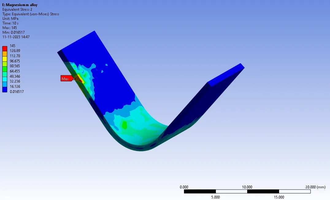
EQUIVALENT VON-MISES STRESS
INFERENCES:
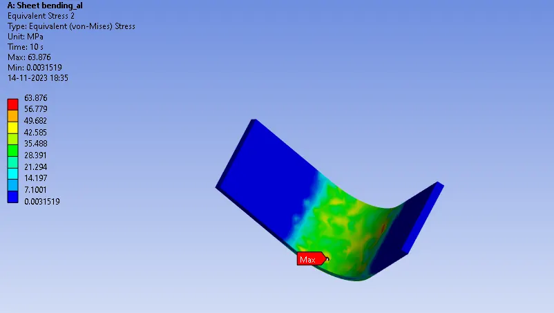
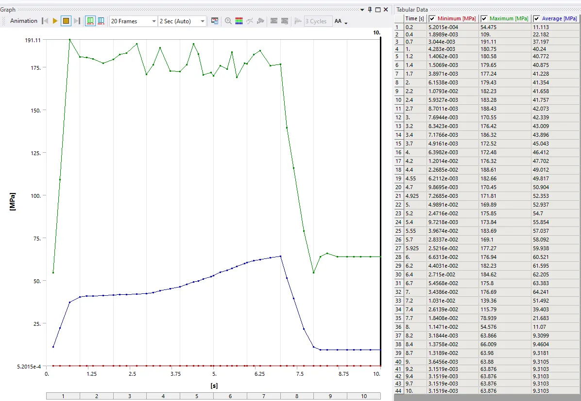
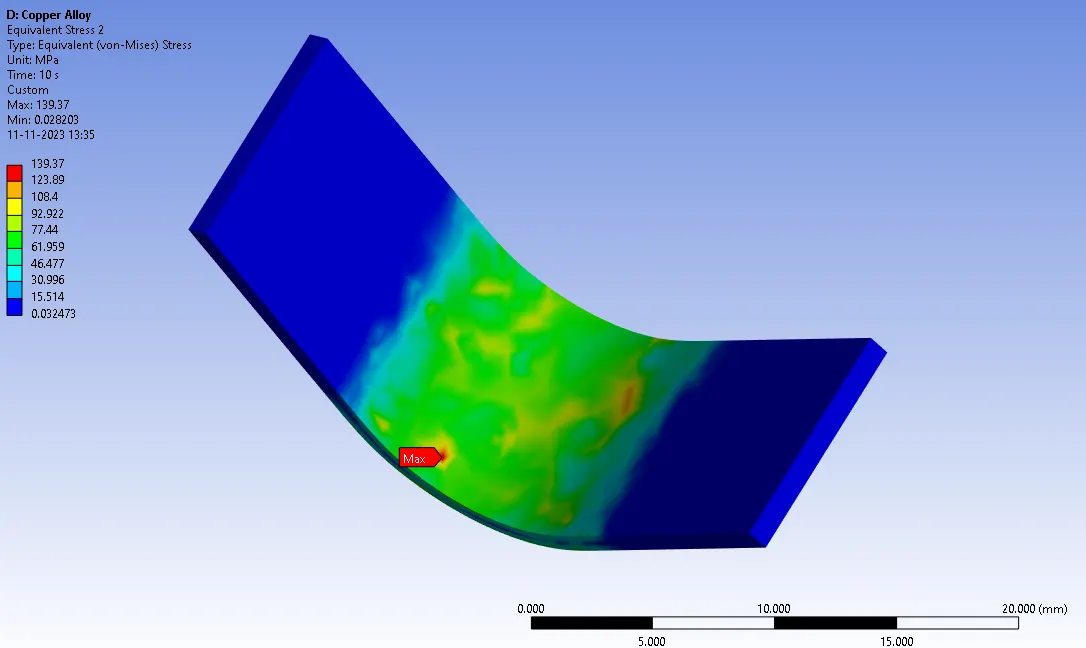
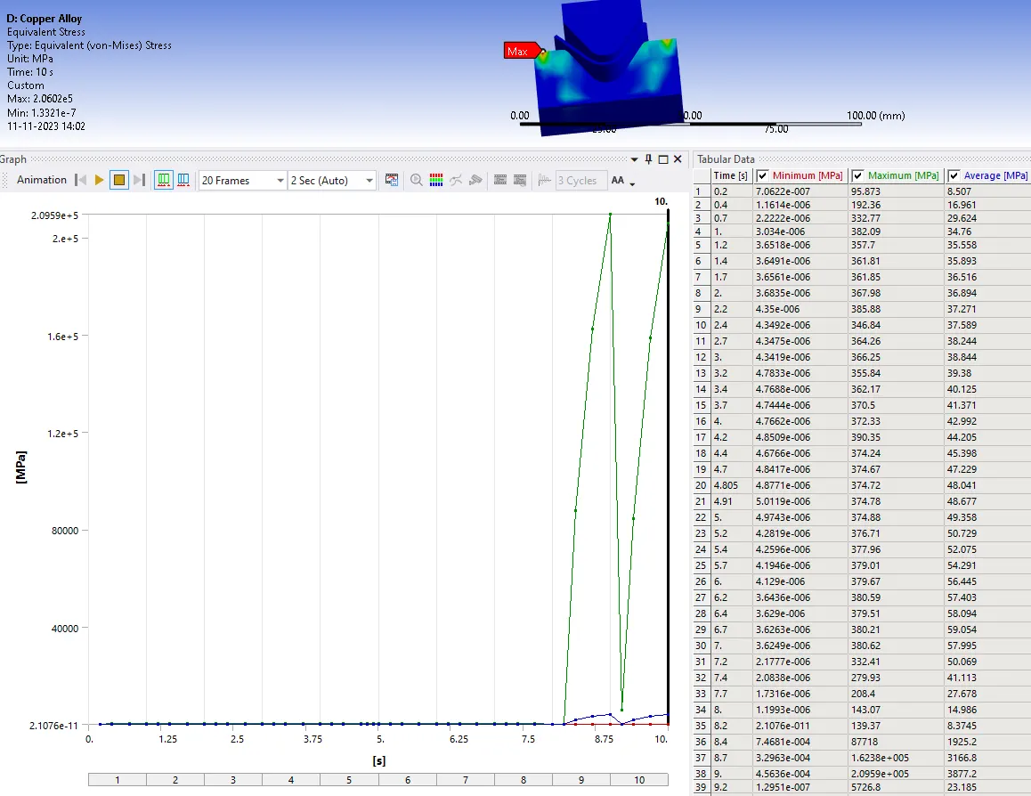
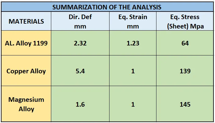
- As per the above results of stress, we can see that the maximum stress in Aluminium alloy 1199 is 64 Mpa, which is less than Copper Alloy NL and Magnesium Alloy NL.
- Also in CASE_1, stress is concentrated in the middle portion, and in COPPER ALLOY CASE and MAGNESIUM ALLOY CASE; stress is distributed over the entire plate.
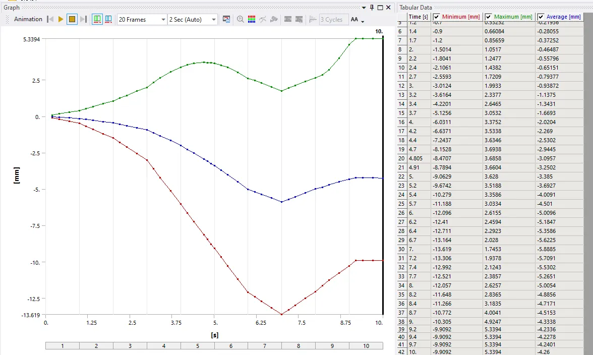
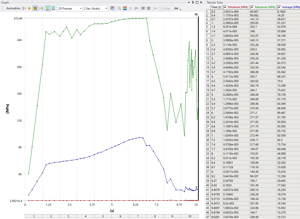
- Also, the plot of the Aluminium Alloy 1199 Sheet is becoming stable after 7.5 s. So after that stress is becoming stable and we can see the plastic deformation. But in the case of Copper Alloy NL and Magnesium Alloy NL, we can see hikes in plots, which can be due to the springback effect.
CASE 2:
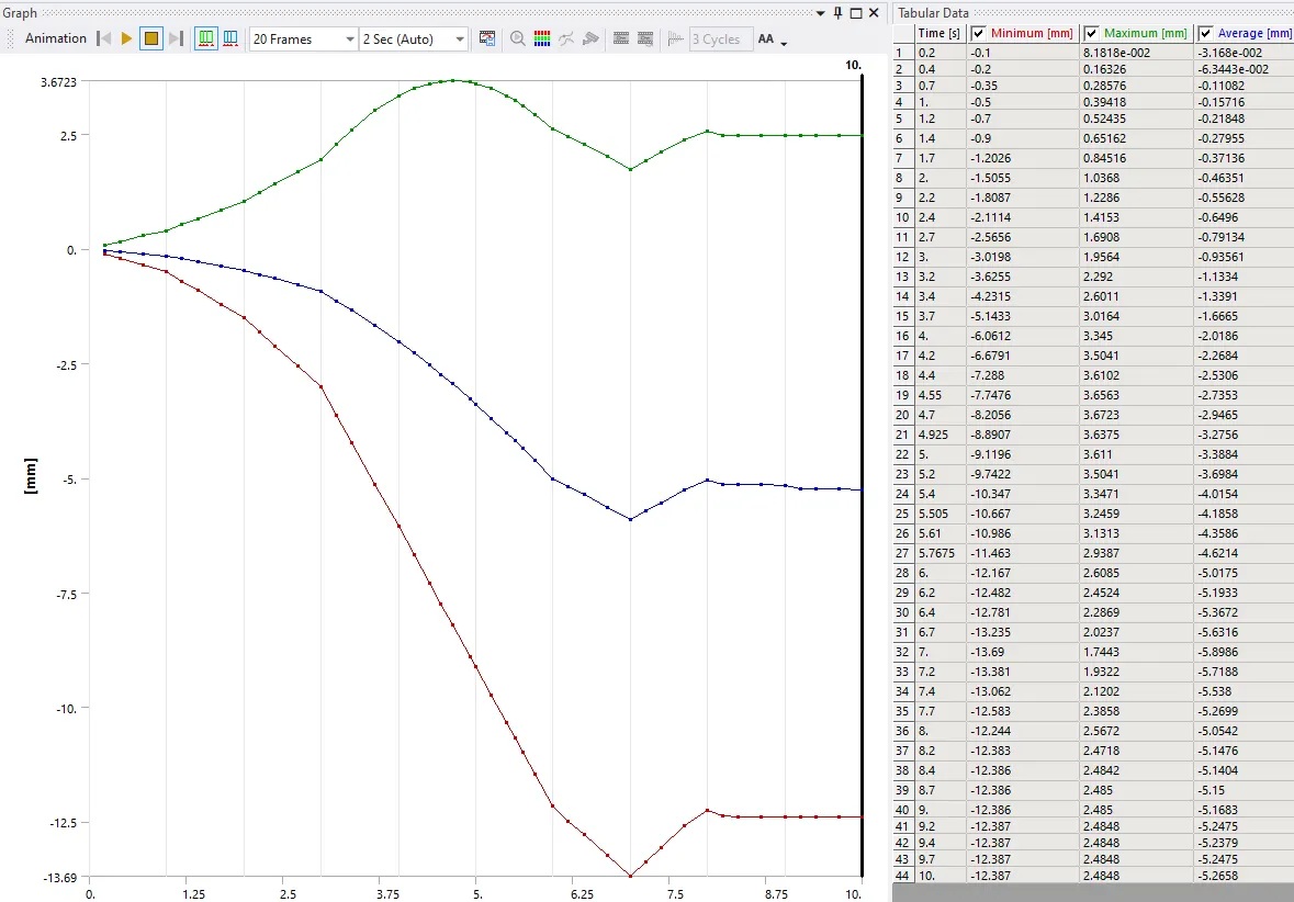
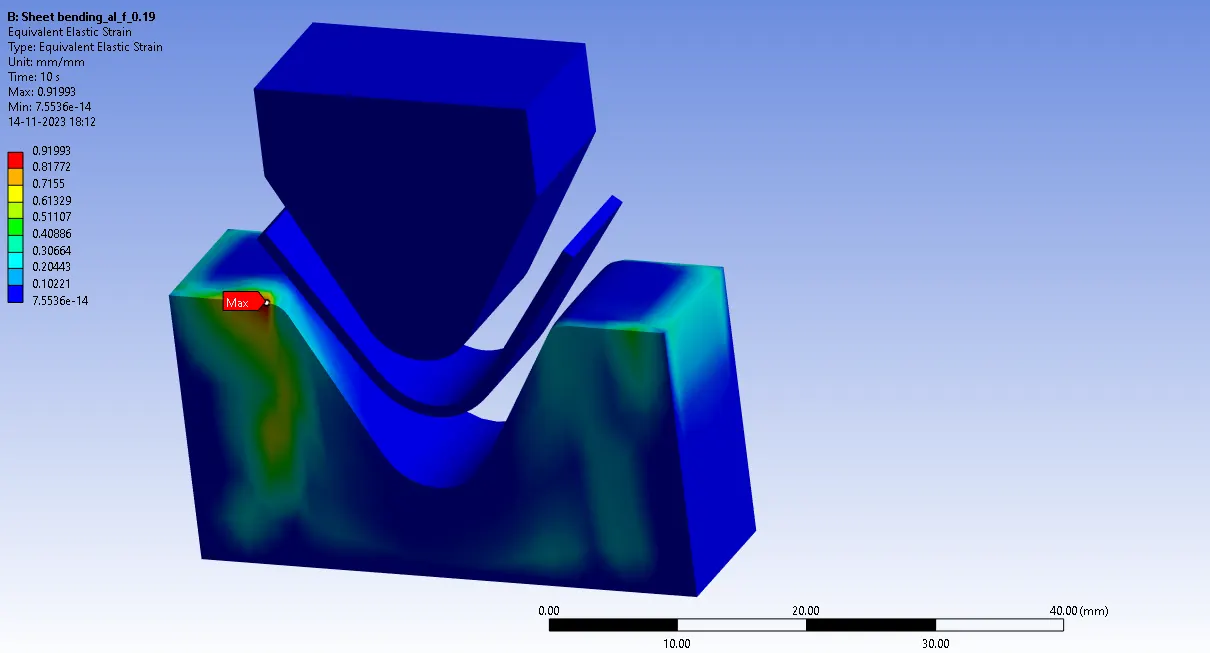
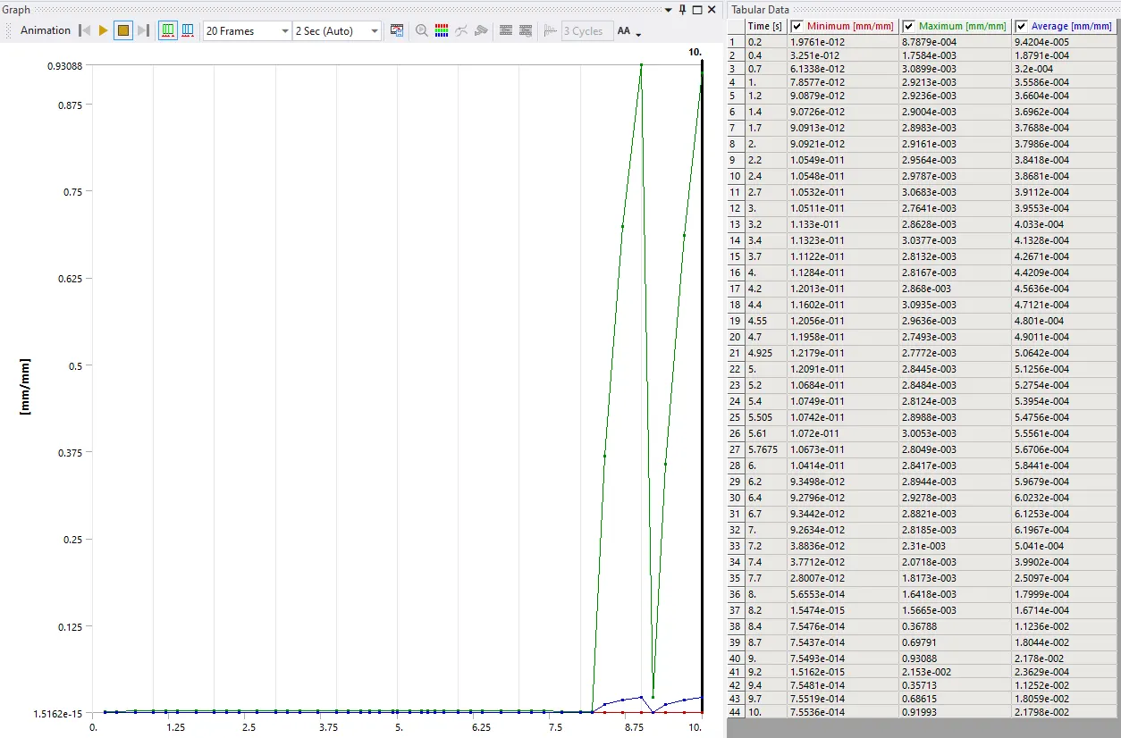
ALUMINIUM ALLOY WITH (Frictional coefficient- 0.19)
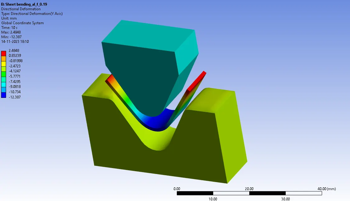
DIRECTIONAL DEFORMATION
ELASTIC STRAIN
EQUIVALENT VON-MISES STRESS
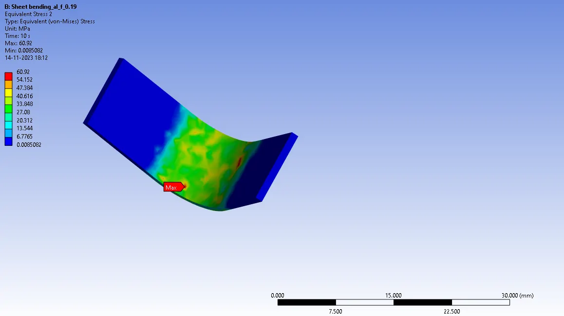
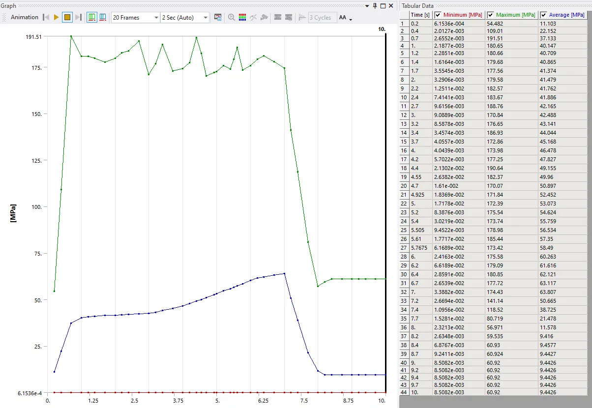
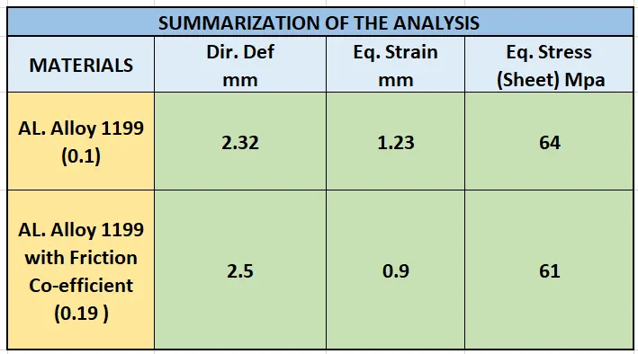
- Here we can see the stress is high in the sheet in CASE_2 compared to CASE_1.
- This effect is due to an increased friction coefficient from 0.1 to 0.19.
- As the coefficient of friction increases, the load for punching the sheet will also increase. Due to that, we can observe high stress in the sheet.
CASE 3:
ALUMINIUM ALLOY WITH (Mesh size of 0.75)
DIRECTIONAL DEFORMATION
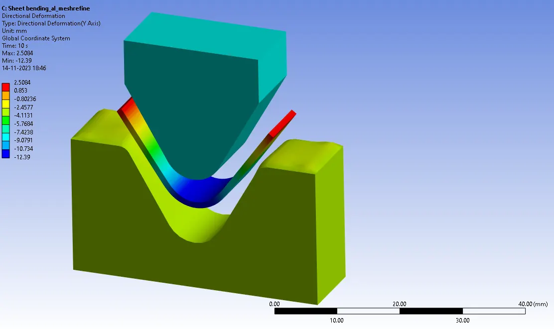
ELASTIC STRAIN
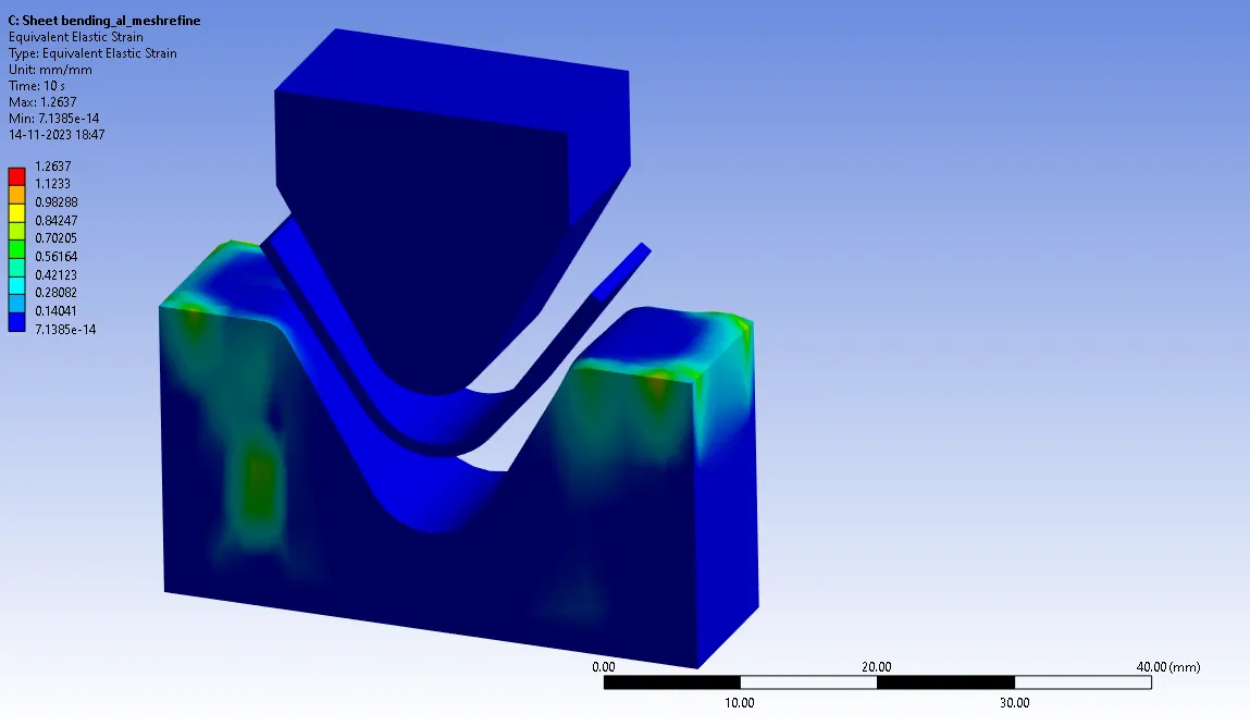
EQUIVALENT VON-MISES STRESS
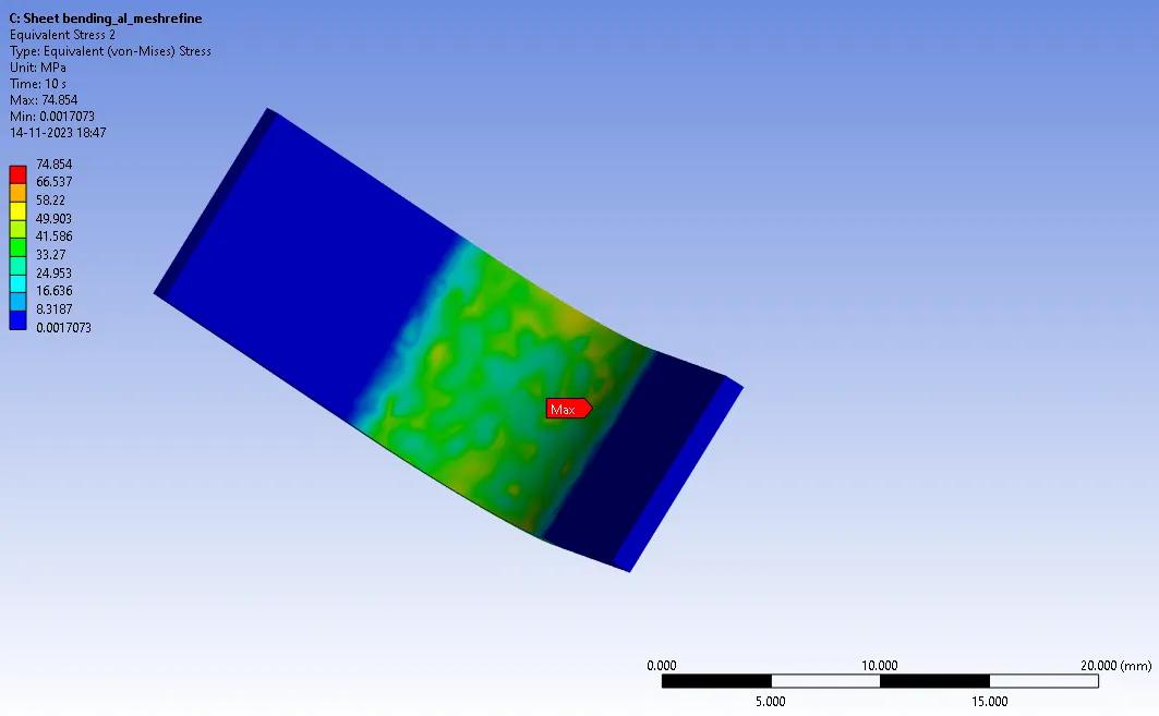
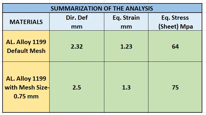
- As in CASE_2, we can observe higher stress values in the sheet compared to CASE_1.
- This result gives more accuracy due to the refinement of Mesh.
- As higher the refinement of mesh, the higher the accuracy of the result.
- We may deduce from the comparison of CASE_1 and CASE_4 that Aluminum Alloy with a coefficient of friction of 0.19 performs better than Aluminum Alloy 1199.Also in CASE_3, the material we have used is Aluminium Alloy. This has a higher value of Young’s Modulus. And as Young’s Modulus is higher, the stress-strain ratio will be higher. So the Value of stress is also higher in CASE_3CONCLUSION:
- The procedure of sheet metal bending works best with ductile materials like copper, aluminum, etc.
- This procedure takes plastic deformation into account as well. Thus, there would be greater stress.
- Bending accuracy can vary depending on the material's characteristics and the location of stress.
- As we see in CASE_1, the central section of CASE_1 exhibits a noticeable stress concentration due to the presence of Aluminum Alloy 1199. This facilitates more effective bending.
- We can see that spring break may have an impact on the plots as well.
- We may deduce from the comparison of CASE_1 and CASE_2 that Aluminum Alloy with a coefficient of friction of 0.19 performs better than Aluminum Alloy 1199. because it can exhibit elastic-plastic behavior and has a greater Young's modulus.
- Additionally, we can see from the comparison of CASE_1 and CASE_3 that aluminum alloy produces superior outcomes due to a larger stress. Because of the finely tuned mesh, we may see ideal stress distribution and excellent bending behavior.
- From CASE_2 and CASE_3, we can see that the outcomes of Aluminum Alloy with a Friction coefficient of 0.19 and with a Friction coefficient of 0.1 are rather similar.
- Additionally, the most used material for metal shaping is aluminum. Thus, based on all of the data above, we can say that aluminum alloy