Week 1 Stress Concentration on a Plate with hole
OBJECTIVE:
- Designing a plate with a single hole or several holes, simulating the two scenarios, and comparing the results of its deformation and maximum stress are the goals of this assignment. Additionally, it is necessary to conclude which of the two circumstances will favor analysis and which scenario will favor the manufacturing process.
PROBLEM FORMULATIONS:
- By doing static structural analysis with ANSYS Workbench, compare the performance of 2 distinct plates with various hole geometries and determine the maximum deformation and Stresses generated for each model.
- Which design should be chosen from the analysis's perspective, and why?
- Which of the designs should be chosen, and why, from the perspective of manufacturing?
- Cases 1 and 2 are represented by the two models below
CASE-1: Rectangular plate with one 60 mm hole
Plate dimensions:
Length=300mm
Height=120mm
Thickness=30mm
Circular Hole at the center:
Diameter=60mm
Plate fixed at left face.
Tensile Load of 500N on the right face depending upon the WCS (World co-ordinate System)
Stress concentration is defined as the localization of high stresses due to the irregularities present in the components and abrupt changes in the cross-section. In order to consider the effect of stress concentration and find out localized stress a factor called stress concentration factor is used. It is denoted by k. The ratio of maximum stress at the cut-out edge to nominal stress is called stress concentration factor. The magnitude of the stress concentration caused by the occurrence of geometric stress concentrator in this case, i.e. the circular holes, in each body is measured by the stress concentration factor k
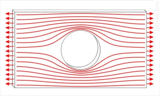
Figure 1. Stress distribution for a plate subjected to tensile load in the section of the central hole
The following list contains some easy rules to follow when it comes to typical techniques for lowering stress:
- As much as feasible, increase the radii of a load path.
- Limit the large feature to a small feature ratio.
- To reduce concentrations, add stress-relieving holes at the end of slits, sharp angles, or fissures.
- To determine whether you are in a radius size zone of declining returns, use stress concentration charts.
Typical problems to avoid include:
- Along the load path, avoid sudden corners.
- Avoid huge transitions while switching between loaded features. The stress concentration will be greatly increased by the stiffness mismatch.
- Don't assume that all features require a radius of the same size. Keep in mind that the stress concentration is based on a ratio (r/b), not a magnitude (r is the radius and b is the breadth in the case of a circular hole).
- If you don't absolutely need to use a sharp corner, don't put too much force on it.
The plate demonstrated in Fig. 1 was subjected to tensile load which, as a result, induced stress in the vicinity of the hole. The material of the plate used for analysis was structural steel and the dimensions are as under:
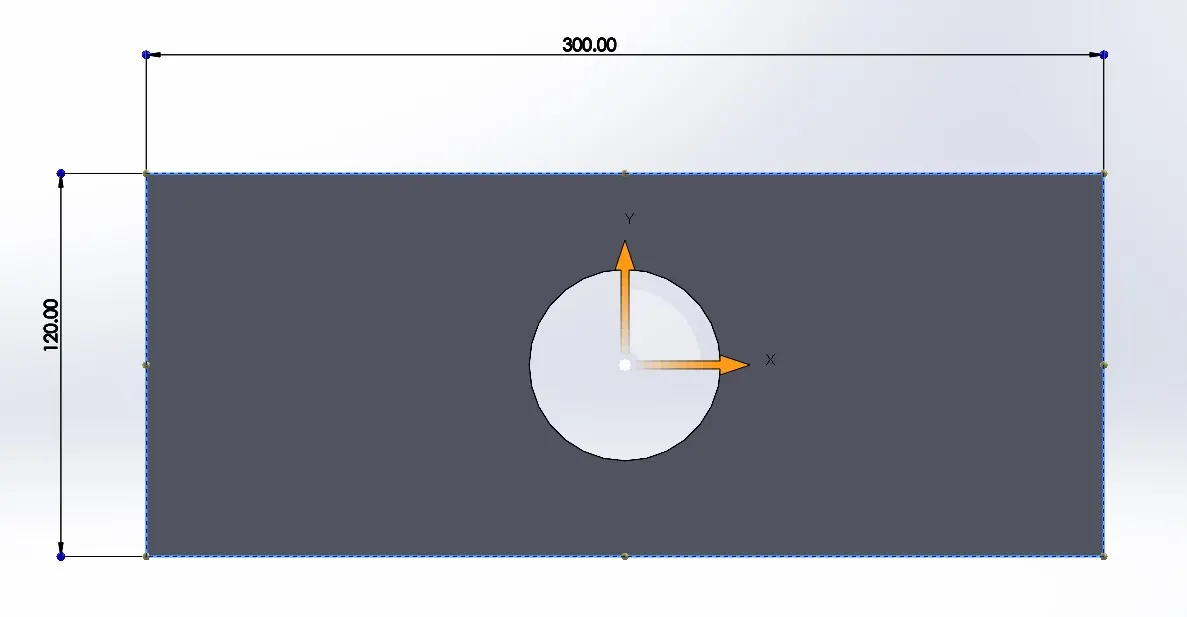
Figure 1.1: Plate Dimensions
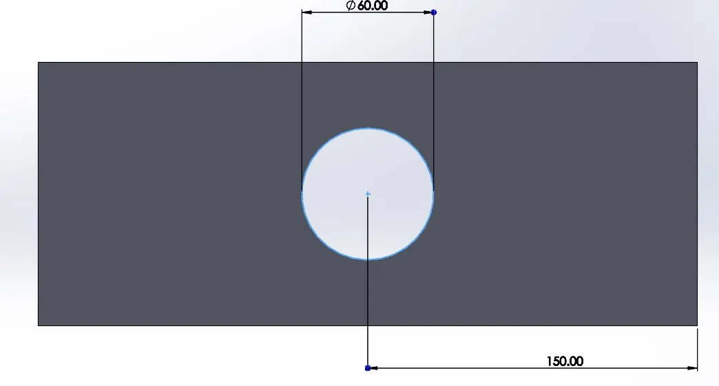
Figure 1.2: Hole Dimensions
Considering the mechanical properties of structural steel, it can be said that the tangential stress and shear throughout the plate will be zero as the stress-induced is principal stress.
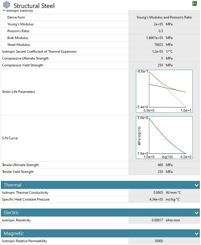
Figure 1.3: Material Properties of SS
Now that the model tab has been updated, we must wait for it to do so before selecting Edit Model from the context menu.
The model tab will then appear.
The mesh type is hexahedron by default, which is not needed in this case. To change the mesh type, right-click on the mesh, insert the method, select the model, and geometry, and apply it, then select the method, "tetrahedron," right-click on the mesh, and click update.
Click on detail view>>default>>element size and choose size as 3
- While carrying out simulation, it is to be noted that the mesh generated must be of good quality. Hence, to obtain accurate results, the mesh generated throughout the face of the plate must be of proper quality. If not, then at least the region around the hole must have best quality elements in the mesh as it is the area of concern in this case.
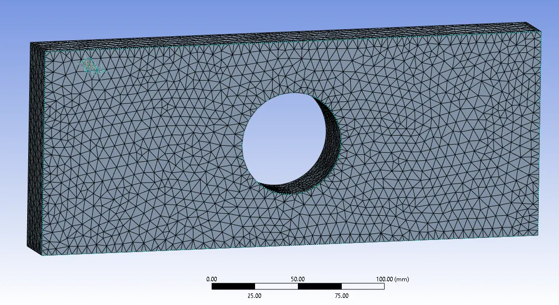
Figure 1.4 Tetrahedron mesh with an element size of 3 mm
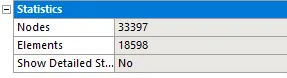
Mesh details about the nodes and elements acquired to mesh the whole geometry
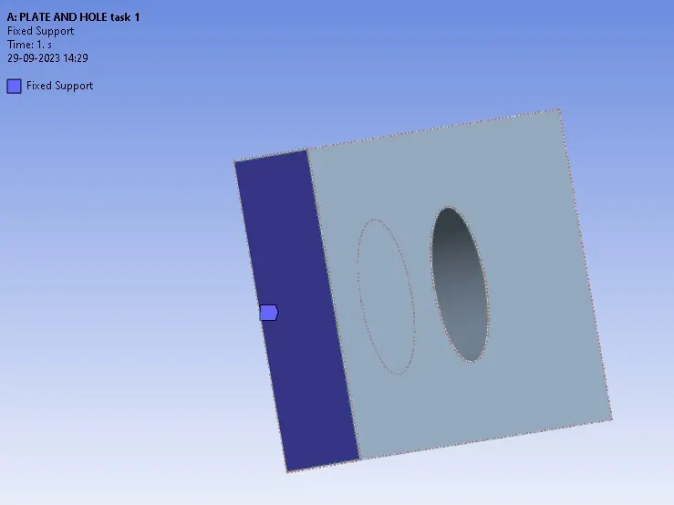
- As per the question, we must add fixed support to the model's left side.
- Click on the static structural element to the right, then select Insert > Fixed Support > Select Left Side of Plate as indicated in the images.
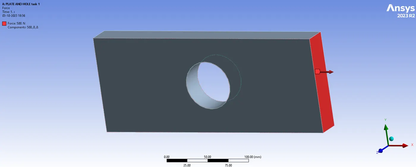
- we have to apply force on the right side of the model in a positive X direction, load of 500N.
- Now we have to apply force and fixed support to the model. For that right click on static structural>>insert>>force>>select the left side of the plate as shown in the figure below
- Next, we must input the desired results, such as the maximum deformation and Von mess stress, after generating the solution.
- Once more, we must come up with the answer; this time, we must examine each one separately.
Max. Deflection/Total deformation-
Case-1
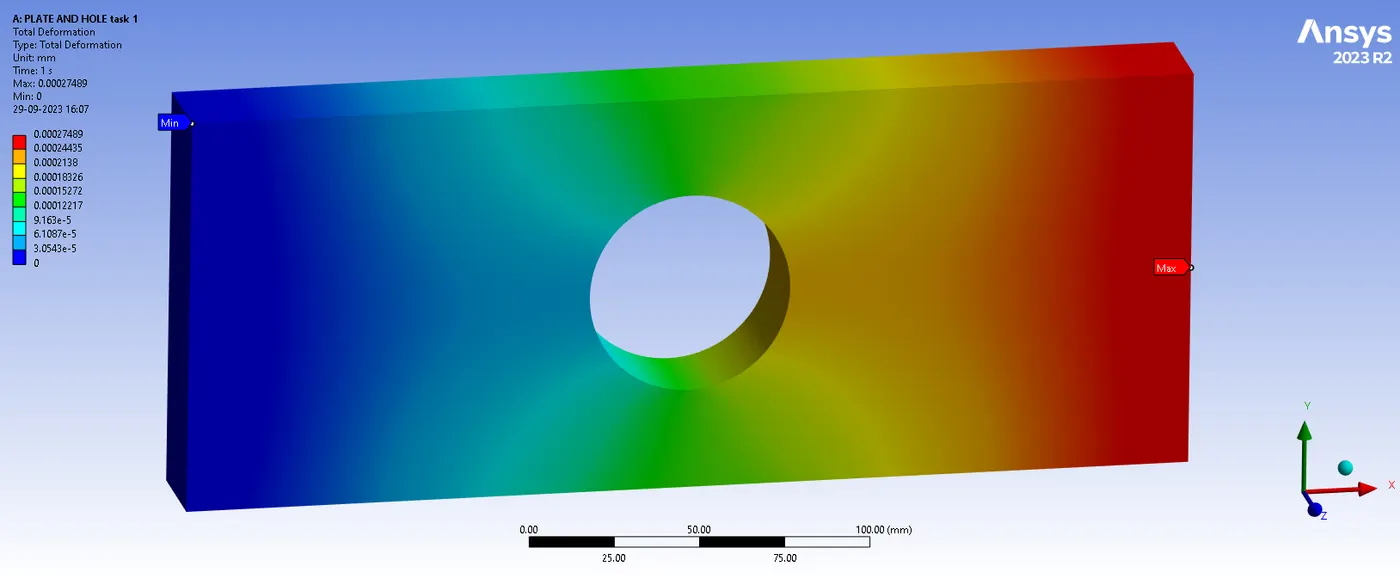
Figure 1.5 Deformation Plot for Plate 1
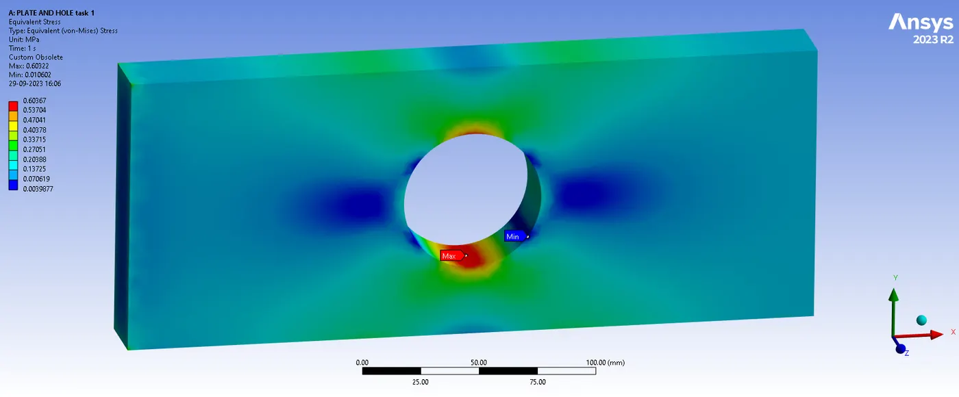
Figure 1.6 Deformation Plot for Plate 1
Case 2: Rectangular plate with 1X 60 mm and 2X 30 mm hole
The plate demonstrated in Fig. 2 was subjected to tensile load which, as a result, induced stress in the vicinity of the hole similar to case-1. The material of the plate used for analysis was structural steel and the dimensions are as below:
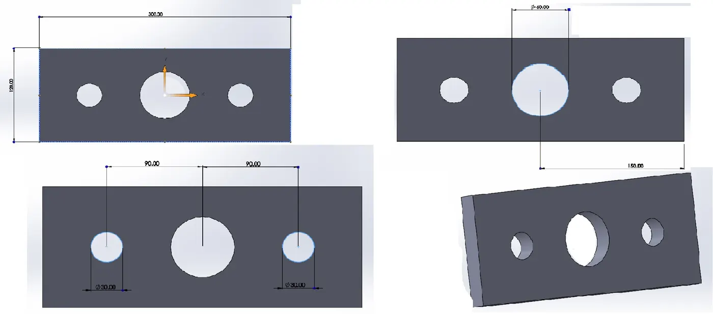
Figure 2.1: Plate & Hole Dimensions
Click on detail view>>default>>element size and choose size as 3
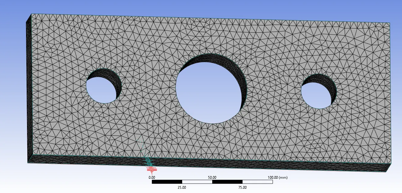
Figure 2.2 Tetrahedron mesh with an element size of 3 mm
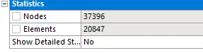
Mesh details about the nodes and elements acquired to mesh the whole geometry
- Similar conditions as of Case-1
- Click on the static structural element to the right, then select Insert > Fixed Support > Select Left Side of Plate as indicated in the images.
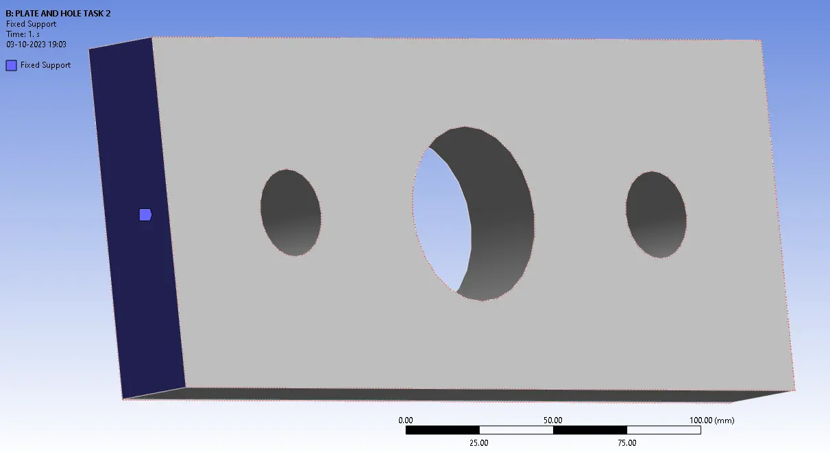
- apply force on the right side of the model in a positive X direction, load of 500N.
- Now we have to apply force and fixed support to the model. For that right click on static structural>>insert>>force>>select the left side of the plate as shown in the figure below
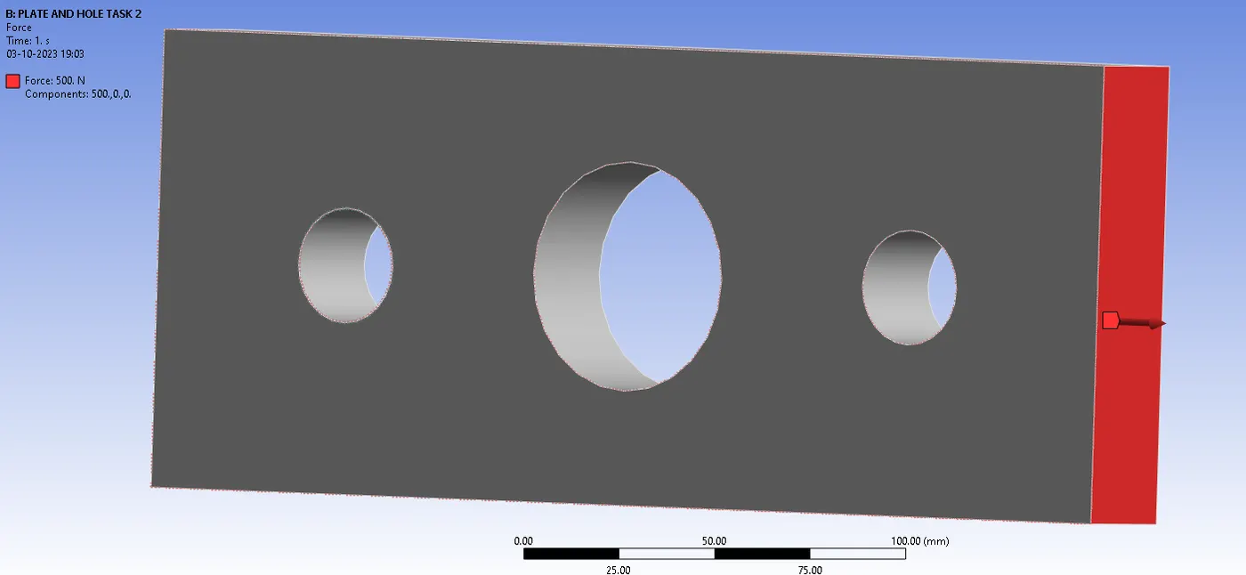
- Next, we must input the desired results, such as the maximum deformation and Von mess stress, after generating the solution.
- Once more, we must come up with the answer; this time, we must examine each one separately.
Max. Deflection/Total deformation-
Case-2
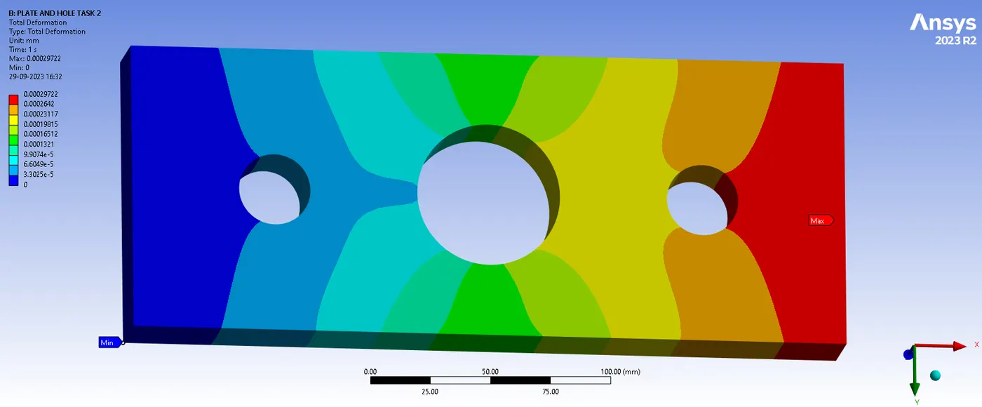
Figure 2.3 Deformation Plot for Plate 2
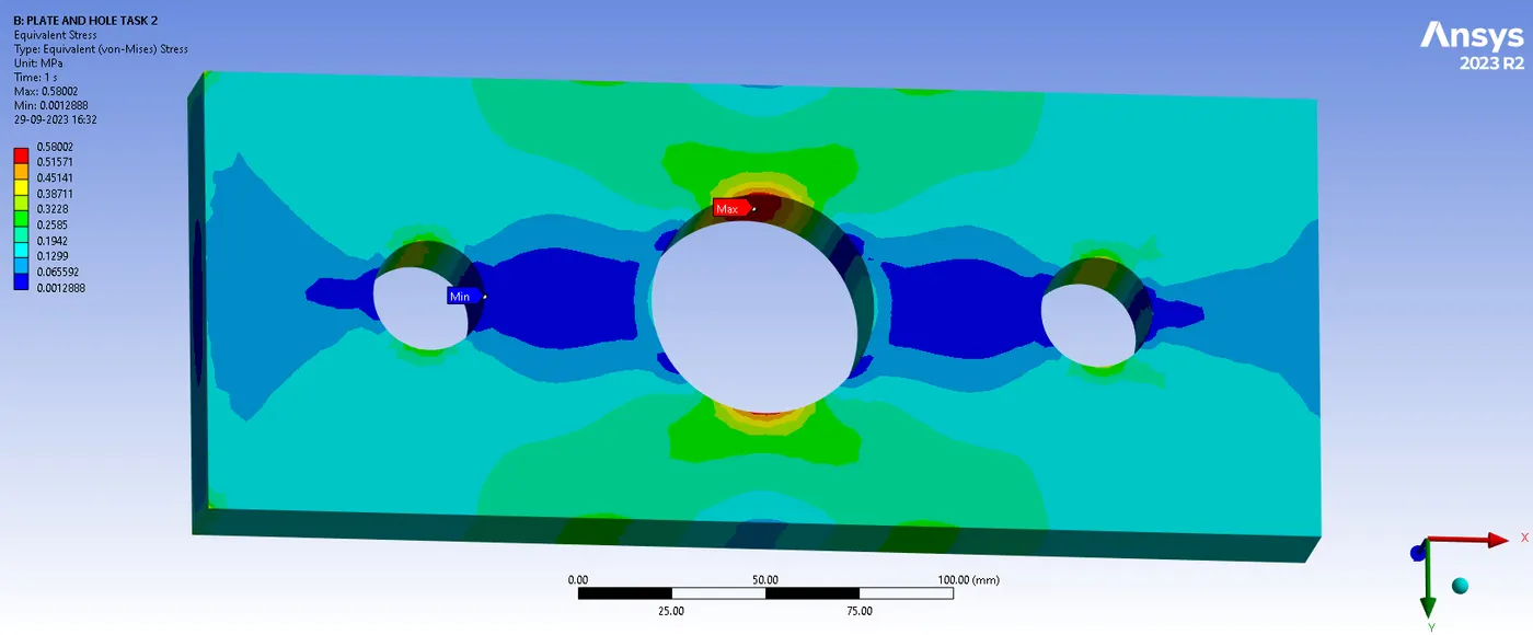
Figure 2.4 Deformation Plot for Plate 2
|
Sr .No |
Deformation (mm) |
Von-Mises Stress (Mpa) |
Factor of Safety |
Margin of Safety (FOS-1) |
|
Rectangular Plate with 1X hole |
0.00027 |
0.603 |
762.85 |
761.85 |
|
Rectangular Plate with 3X hole |
0.00029 |
0.580 |
793.1 |
792.1 |
Table 1: Comparison for both Cases results
- It is evident from the above result that in Case 1, the maximum stress is frequently seen close to the hole and can be much greater than the average stress across the object's cross-section.
- However, Case-2's stress levels have decreased and the concentration of stress has been reduced as stress-reducing holes have been inducted.
Analytical Point of View
Due to its greater stress value and ease of analysis, the plate with 3 holes should be chosen from an analytical perspective. To comprehend the impact of tensile stresses on a plate having a relief feature, such as a hole, we will do a straightforward analytical experiment. The overall difference in deformation between the plates is 20 nm, indicating that the plate with one hole deforms 20 nm less than the plate with three holes, but the stress factor is 0.02 Mpa difference compared to Case-1, we can't neglect the value as it creates a greater impact in terms of Factor of Safety (UTS/ Allowable Stress) and Margin of Safety.
We don't consider the design's weight, price, or manufacturing processes when doing our research.
Manufacturing Point of View
In terms of production, the plate with single holes should be selected. Cost, weight, and machinability of the material are important considerations when making a manufacturing decision. This plate is more cost-effective and has optimum stress qualities. The lead time for plate 1 is much lower compared to plate 2 as it can be machinable in 2 passes whereas plate 2 will need one pass for milling and the rest 4 passes for drilling and finish machining.
Any manufacturer's top priority is to cut down on both manufacturing time and material waste. Therefore, the first example has a relatively simple design and requires less production time and material waste, but case two requires more manufacturing time and material waste which is higher.
POINT OF VIEW:
- From the design point of view plate 2 has better stress-relieving features as compared to Plate 1.
- Manufacturing Plate 1 with a hole would be much easier than Plate 2 as it would save time cost and money and most importantly waste reduction would be minimal.
- Mesh of Hexaheadron would have given better results than of tetrahedron mesh as tet mesh possesses stiffness characteristics while hex mesh doesn't have characteristics.
-
The stress in the plate gradually increased from the edge towards the hole and became maximum on its circumference. This can be visualized by studying the graph plotted that shows that the nodes nearest to the discontinuity in plate faced maximum stress than those that were located comparatively further: