Week 3 Verification of Weld Joints
AIM:
To compare the findings of static structural analysis, such as directional deformation, stress, and strain development on welded joints, on welding joints made of three distinct materials.
OBJECTIVE:
Case 1. Stainless Steel: In this case, the material of the plates must also be the same. Use Stainless steel for both weldments and plates. No need to add flux to the weldments.
Case 2. Aluminum Alloy: The material chosen for this case is Aluminium alloy(high strength, wrought). [Plate material to be used is stainless steel]
Case 3.Bronze: In order to simulate "Brazing", you should be using bronze as the weld material. Assign Stainless Steel to both plates and Copper to the "Ribs".
Run the simulation for a load of 15000N that will be applied at the rectangular hole in the small plate(Same as in the video).
For each case, find out the Directional Deformation and equivalent strain experienced by the setup. Identify the weld joint that experiences the highest equivalent stress in each case and compare the results for all three cases
- Getting ready with the Weld Joint assemble model developed in Solidworks and importing it into the Ansys Workbench for static structural Analysis.
- Apply Boundary Conditions by setting up the contacts and applying the fixed and load boundary conditions.
- Determine Directional Deformation, Weld Stress and Elastic Strain results for the performed simulation.
- Repeating the simulation for other cases of different materials.
- Evaluation and comparison of the results.
THEORY (INTRODUCTION):
Welding is a fabrication process whereby two or more parts are fused together by means of heat, pressure or both forming a join as the parts cool. Welding is usually used on metals and thermoplastics but can also be used on wood. The completed welded joint may be referred to as a weldment.
- Some materials require the use of specific processes and techniques. A number are considered 'unweldable,' a term not usually found in dictionaries but useful and descriptive in engineering. The parts that are joined are known as parent material. The material added to help form the join is called filler or consumable. The form of these materials may be referred to as parent plate or pipe, filler wire, consumable electrode (for arc welding), etc.
- Consumables are usually chosen to be similar in composition to the parent material, thus forming a homogenous weld, but there are occasions, such as when welding brittle cast irons, when a filler with a very different composition and, therefore, properties are used. These welds are called heterogeneous.
- The completed welded joint may be referred to as a weldment.
The American Welding Society recognizes butt, corner, edge, lap, and tee joints as the five different types of joints.
- At the junction, where real welding might take place, these setups may have different configurations, Although there are many different kinds of butt welds, they all belong to one of three groups: open or closed butt joints, double welded butt joints, and single welded butt joints.
- A junction that has only been welded from one side is known as a single welded butt joint.
- When the weld is welded from both sides, a double-welded butt joint is produced.
The depths of each weld might differ somewhat while double welding. A form of connection known as a closed weld is one in which the two elements that will be welded are in contact with one another when welding. When there is a tiny space between the two components during the welding process, the junction is called an open weld.
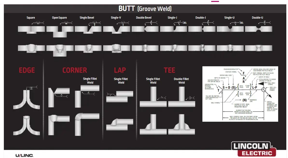
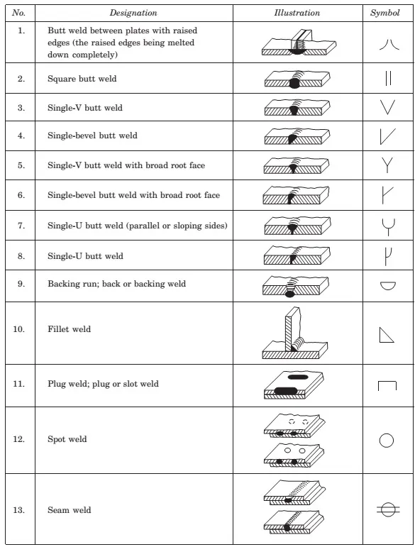
The earlier figure denotes different kinds of welded joints while the later figure denotes weldments with symbols.
Analysis Setup:
For three separate conditions involving specific materials, a static structural study of the welded joints of the ribs and plats is to be carried out.
In all three scenarios, Stainless steel is specified as the material of the plate.
- Geometry
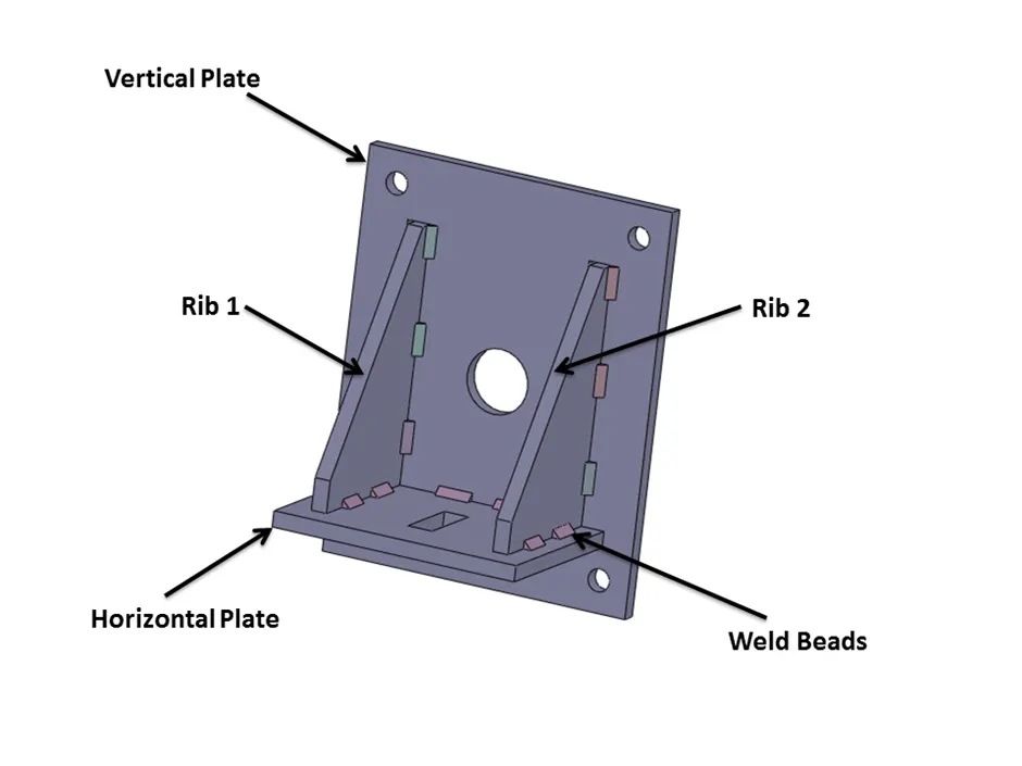
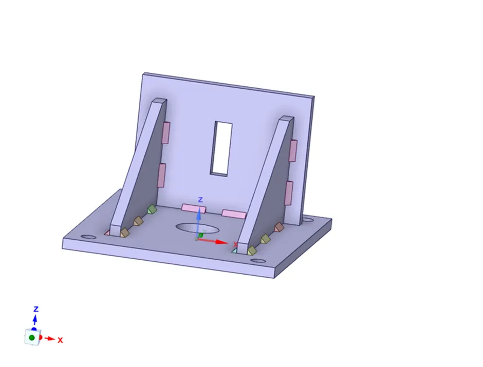
The 3D assembly model of the Weld Joints is developed in SOLIDWORKS is shown in the figure below:
Material Properties :
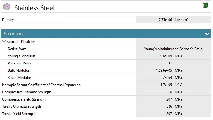
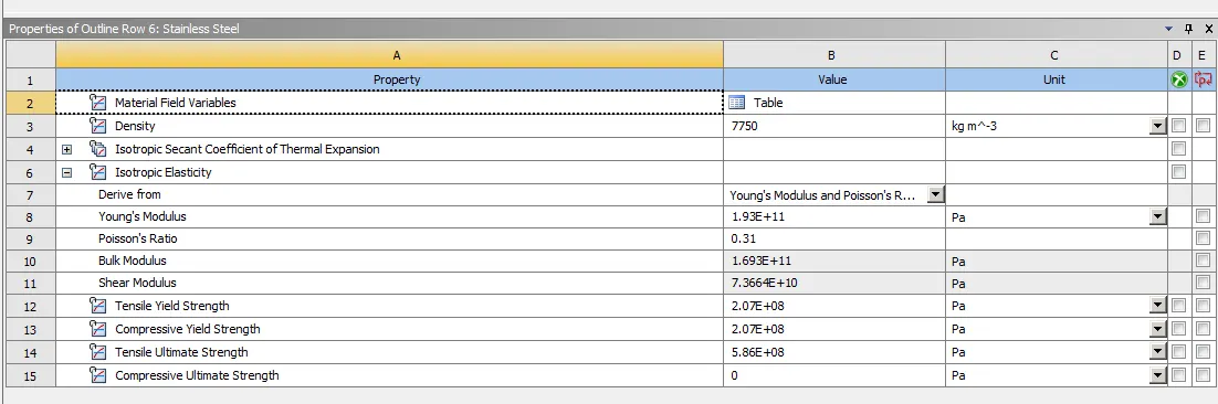
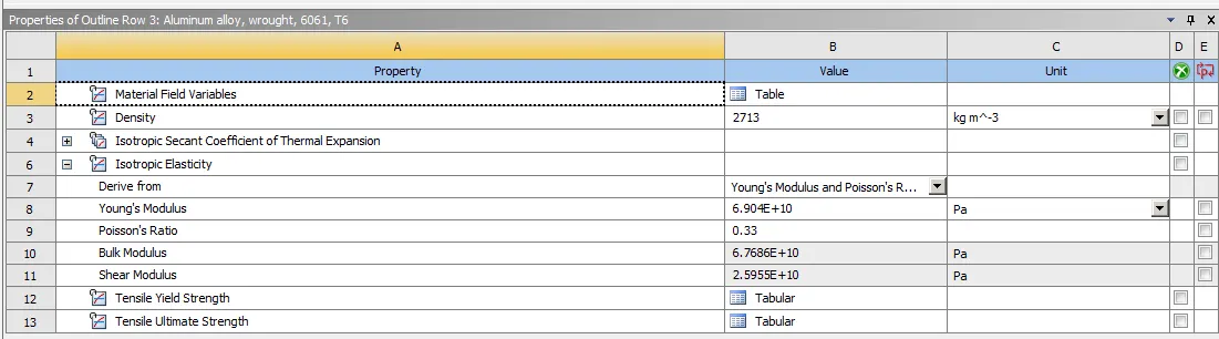
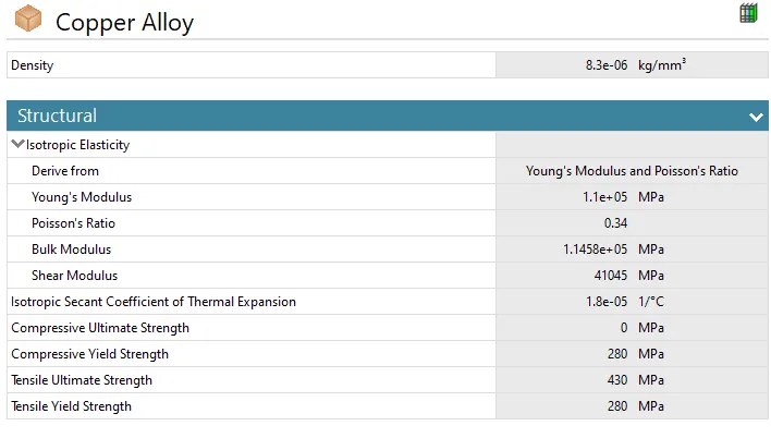
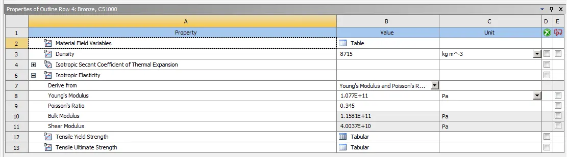
The material of the Plates is set to be stainless steel for all the 3 analysis cases. The material of Ribs is Stainless Steel for the first 2 cases, but for the third case, the material is assigned as Copper. The material of weldments is different for each. For the first case, the material structural steel is assigned, Aluminum Alloy for the second, and Bronze for the third case. The material properties are given below:
- Stainless Steel
- Aluminum Alloy
- Copper
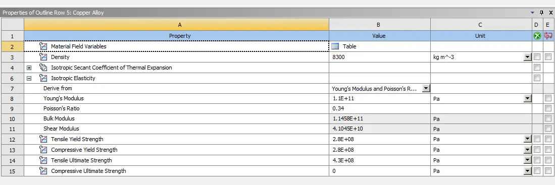
- Bronze
We take up the first case where all the geometry has been applied only with stainless steel.
The geometry is imported into space- -claim and can be seen below with two plates attached with strength reinforcement ribs by weldments.
- After opening a fresh Ansys file, the static structural module was dragged onto the project window.
- The model was opened in the space claim after it was imported into the geometry tab to check for any discrepancies for any adjustments that need to be made
- To proceed with further setup, open the module tab. We could see several sections from the geometry choice, and the name has been changed as required
- Material: Select the contact tab and use the right-click menu to rename according to the definition.
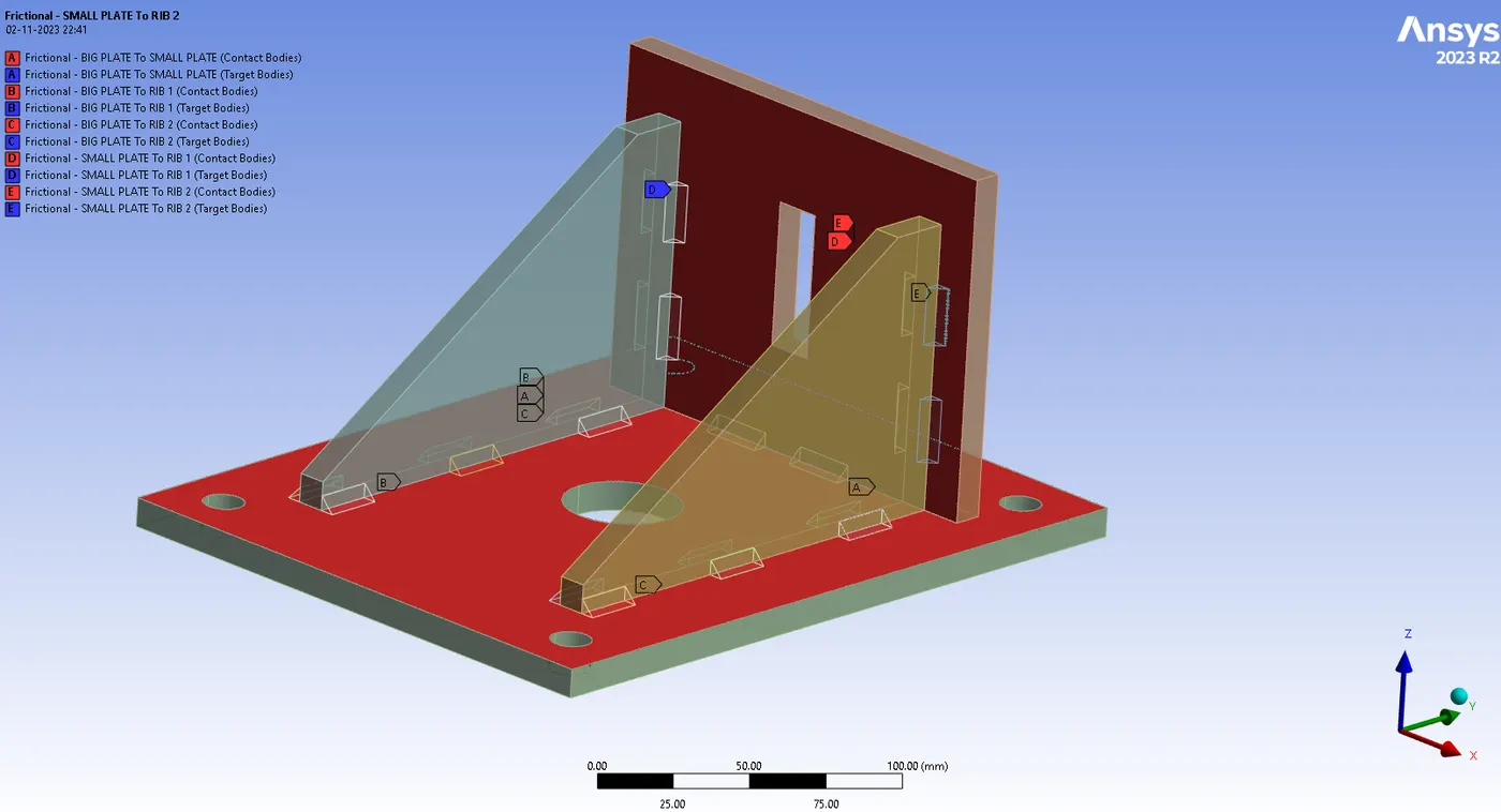
- Apart from the welded joints that will be bonded, the contact between the large plate, small plate, and rib is frictional.
- Choose each of the five contacts that were just discussed, containing the contact between the large and small plates, and ribs
- Contact Details
With a frictional value of 0.2, the direct contact between the ribs and plates is a frictional contact. - Since all of the plates are flat, it is possible to choose the contact and the target for each contact arbitrarily while taking into account the benefits of utilizing Augmented Lagrange to prevent interpenetrations.
- This formulation is utilized for all frictional interactions.
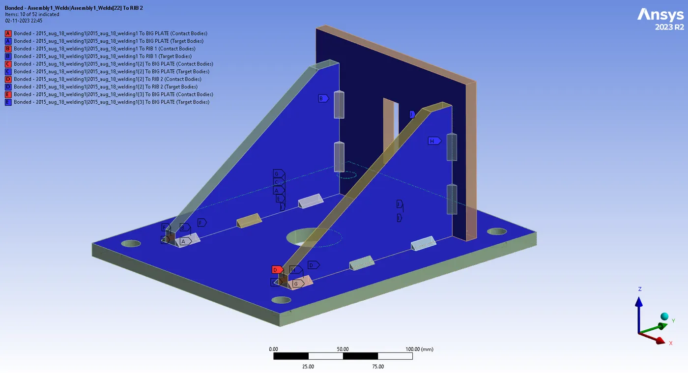
- All the contact of weldments with the ribs and plats are set as bonded.
MESHING:
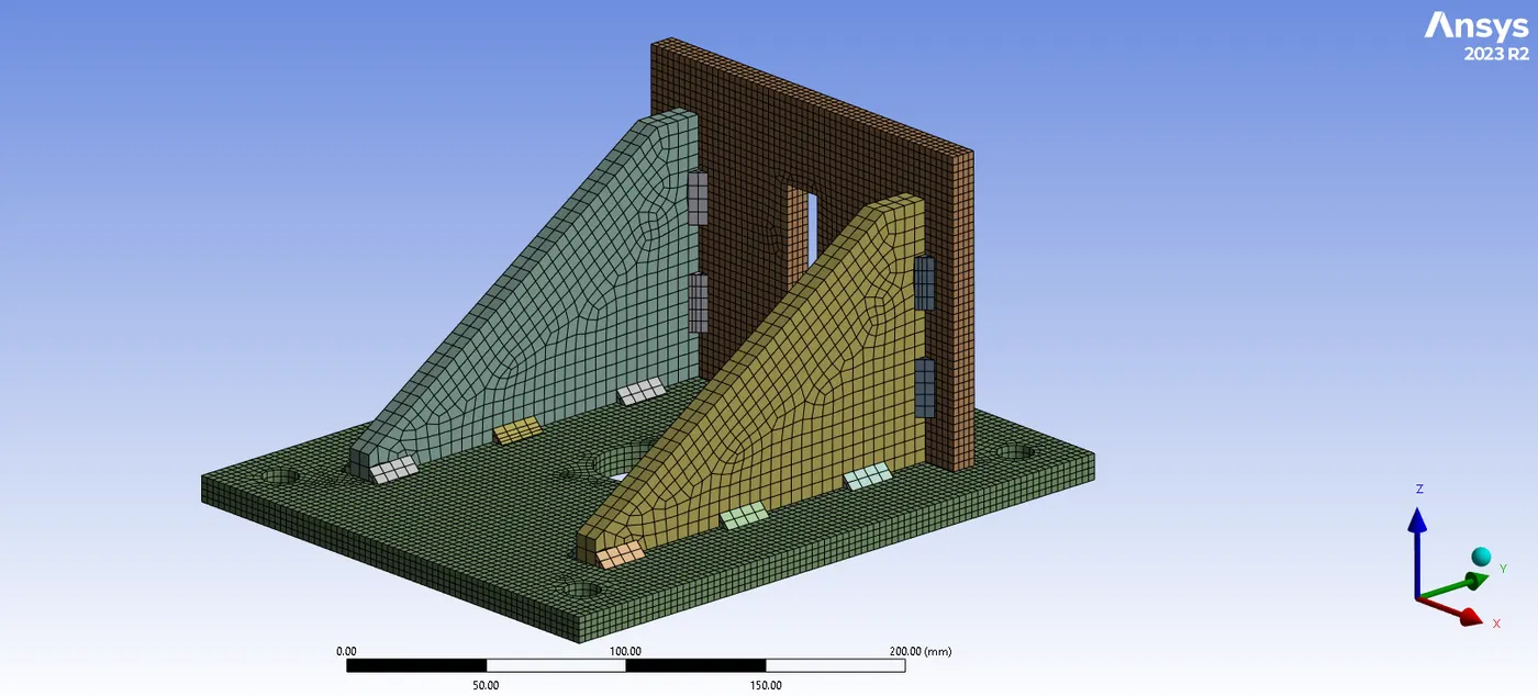
- Select the small and big plates using the solid filter and go to the mesh tab, right-click>insert>sizing. A sizing of 3mm was done and the mesh is generated.
- A body mesh with a 5mm refinement was used on the rest of the geometry. There have been 161894 nodes and 34879 elements produced in total. The mesh that was created is seen below:
- For the analysis setting up the large deflection was turned 'on' because we will be able to capture the non-linearities in the model.
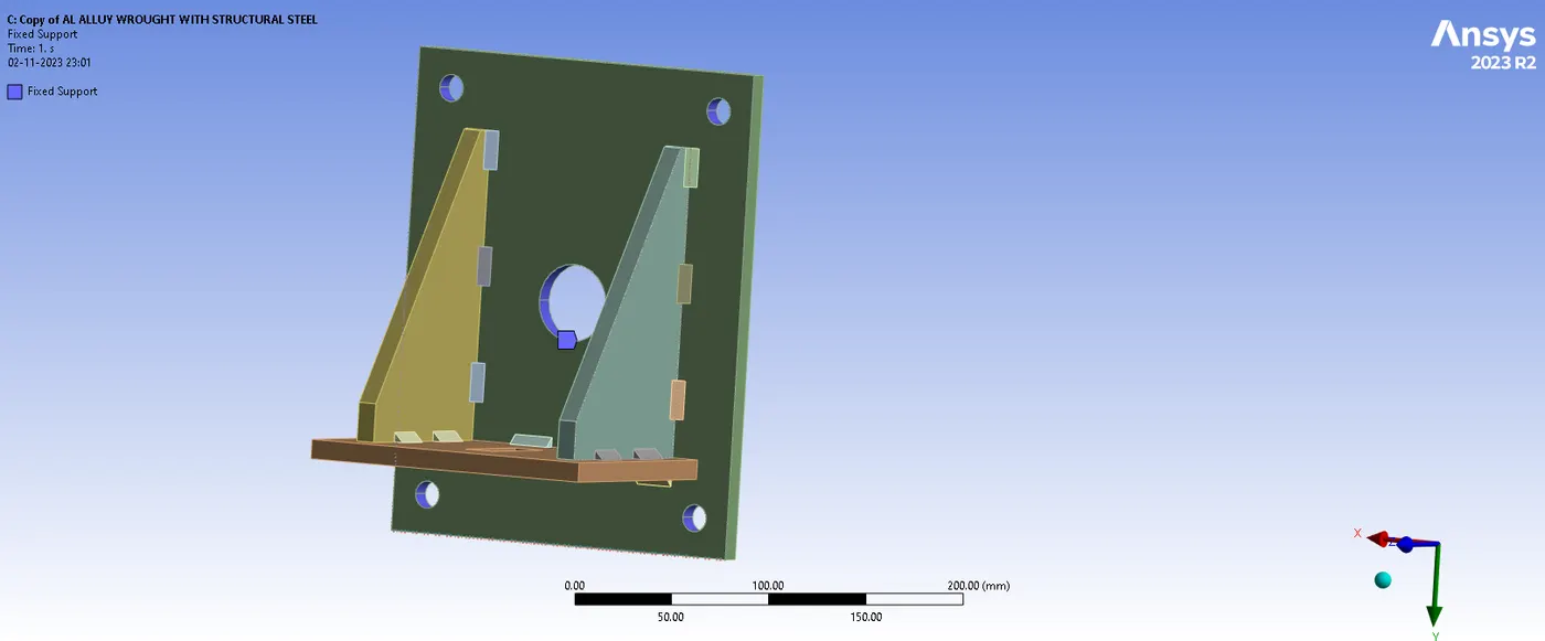
- If we look at the geometry of the model, it's going to be fixed on the wall by bolted joints, and the load is provided to the hole as shown below.
- To fix the geometry, right-click static structural>insert>fixed support and select the surfaces shown below.
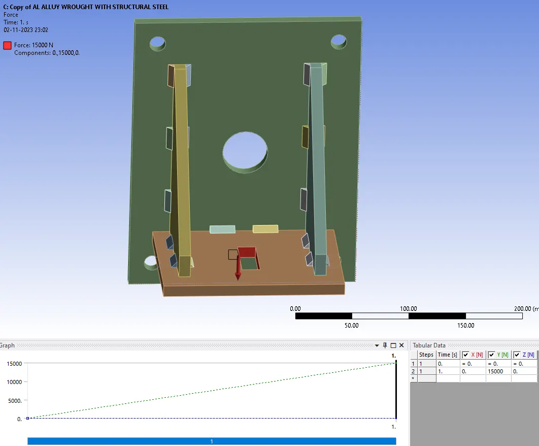
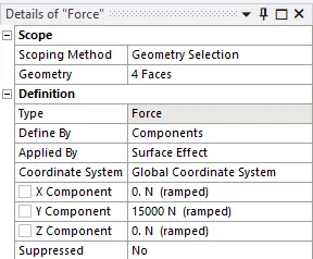
- The required force was inserted by right-clicking static structural>insert>force. Select the surface of the rectangular hole as shown below and assign a load of 15000N which is acting along the y-direction.
- From the solution, the output for the simulation was requested. Since the deformation happens in the y-direction, it's assigned by right-clicking solution>insert>deformation>directional, and changing the orientation to the y-axis.
- Again, from the solution, the equivalent elastic strain was requested, and to observe the strain around the ribs we may select the two ribs using the solid filter.
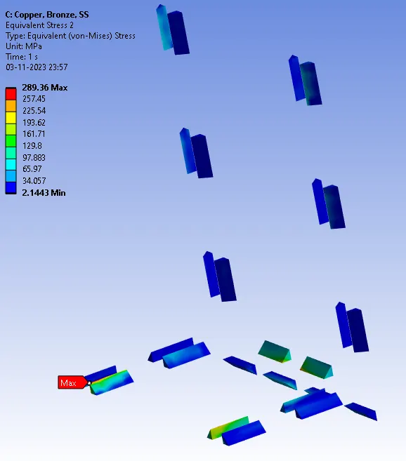
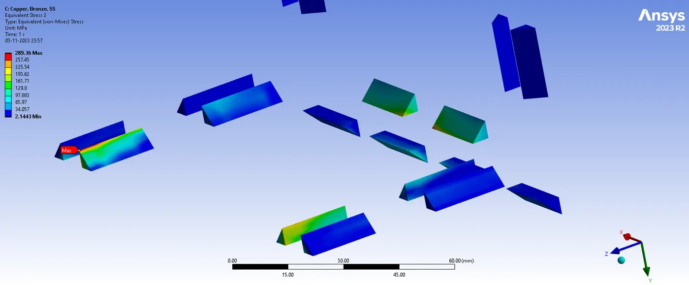
- To observe the stress induced at the welded joints, right-click solution>insert>equivalent stress, and select all the welding joints.
- After providing the required parameters for the output, click solve.
- The same procedure was followed for case 2 and case 3, by changing the material types.
- POST-PROCESSING:
After analyzing the project we will look at some results as written above, we have three different cases for this solution, as material changes in each case.
Case: 1
Material for Plates: Stainless Steel
Material for Ribs: Stainless Steel
Material for Weld Beads: Stainless Steel
Directional Deformation
The maximum total Deformation was found to be 0.4mm
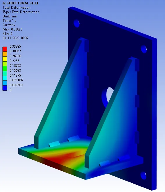
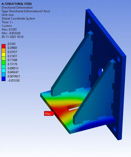
The directional deformation in Y-Axis was found to be similar to total deformation.
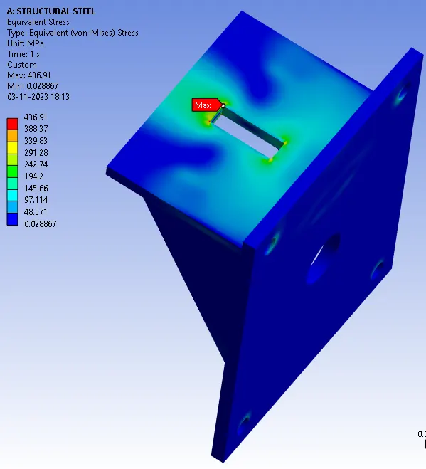
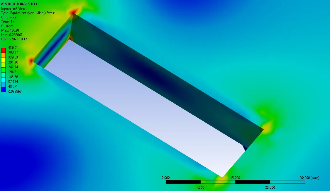
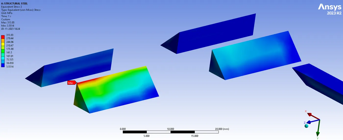
The Equivalent (Von-Mises) Stress for the case obtained from the analysis is shown below.
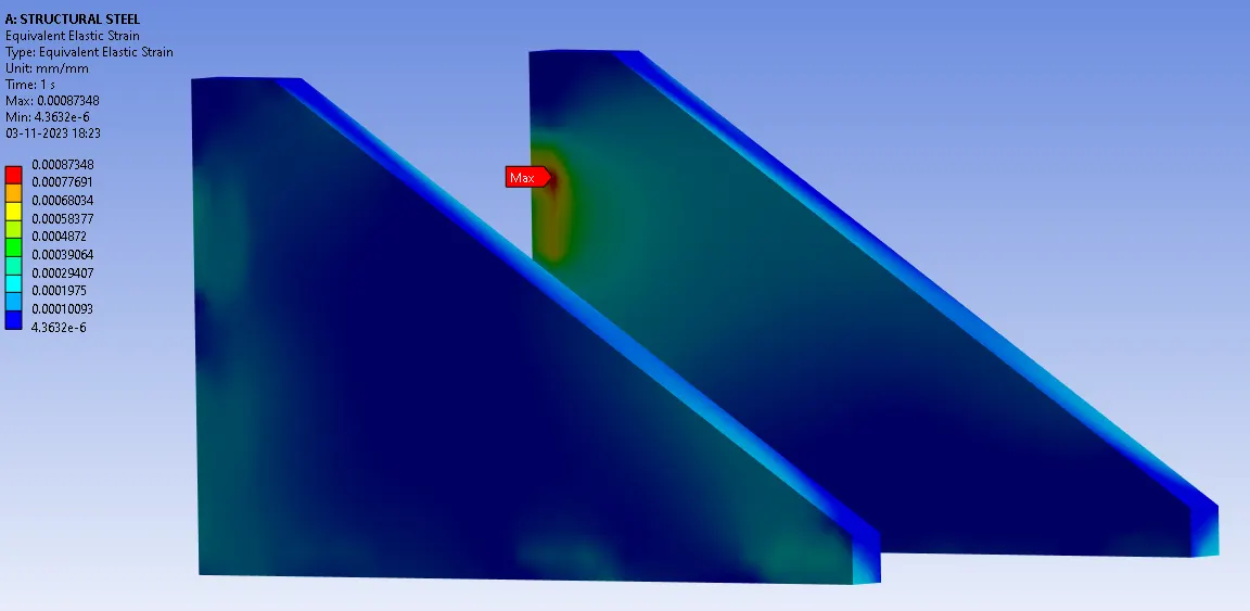
Equivalent Elastic Strain (Ribs)
Equivalent Stress (Weld Joints)

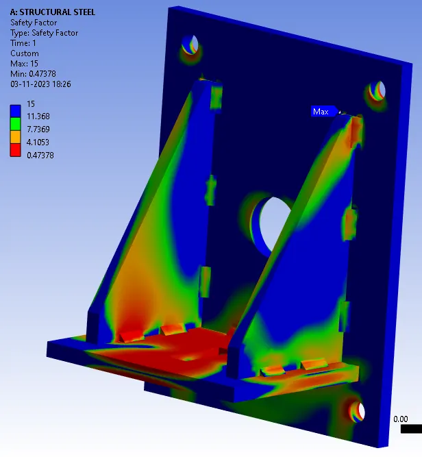
Safety Factor:
The maximum Safety factor was found to be 0.47 for this stainless steel
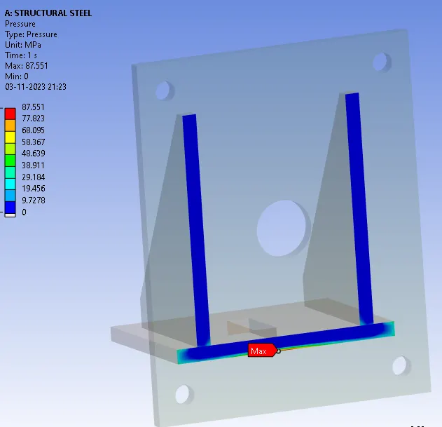
CONTACT PRESSURE:
The maximum contact pressure was found to be 87.551 found in the ribs and the bigger plate
Case: 2
Material for Plates: Stainless Steel
Material for Ribs: Stainless Steel
Material for Weld Beads: Aluminum Alloy
Directional Deformation
The maximum total Deformation was found to be 0.36mm

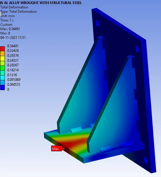
The directional deformation in Y-Axis was found to be similar to total deformation.
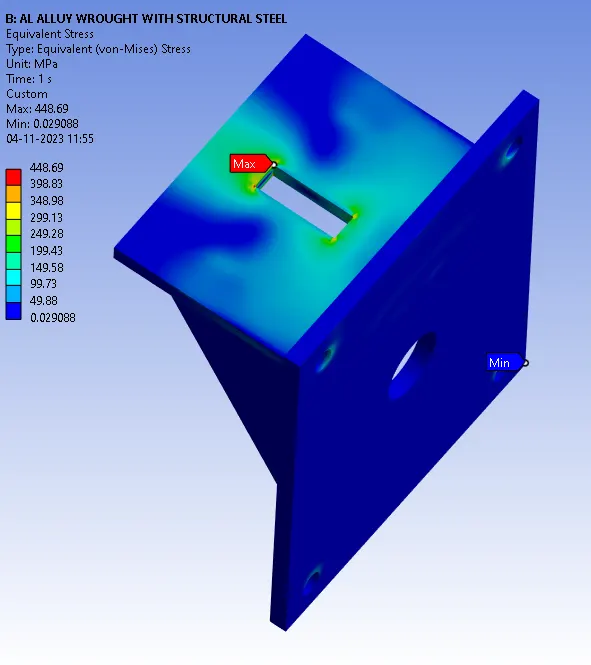
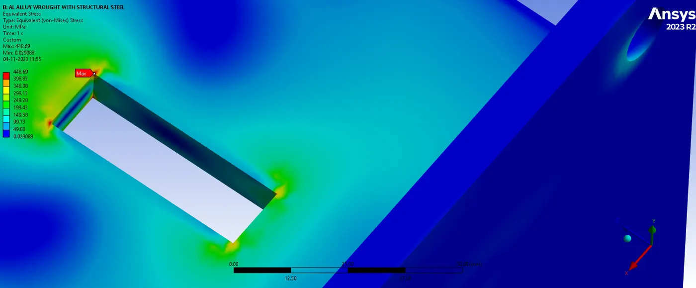
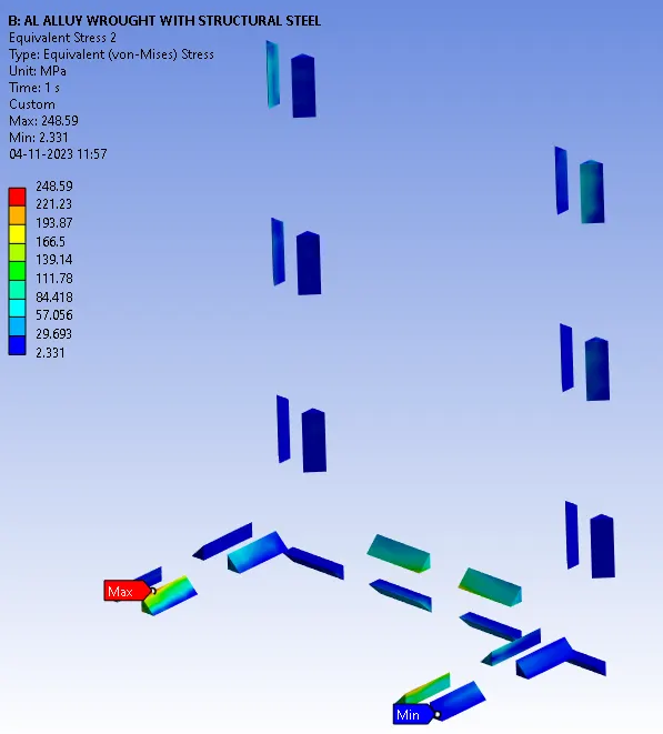
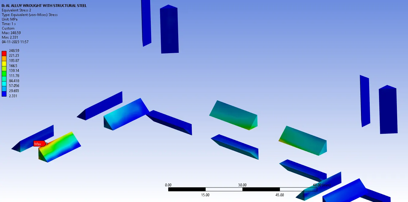
The Equivalent (Von-Mises) Stress for the case obtained from the analysis is shown below.
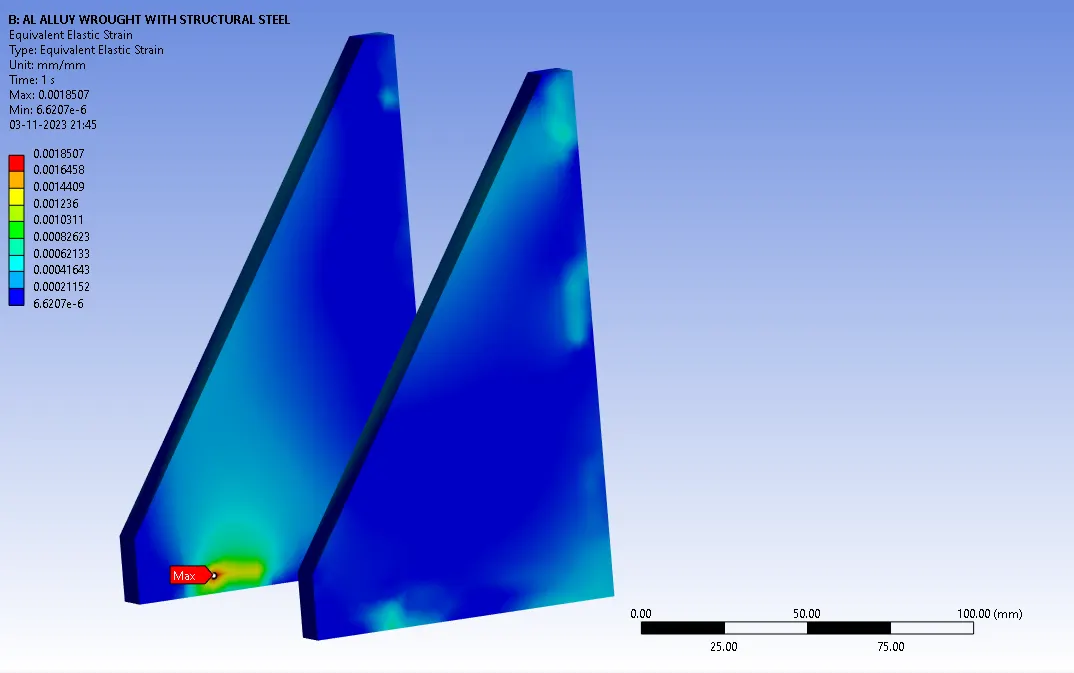
Equivalent Elastic Strain (Ribs)
Equivalent Stress (Weld Joints)
Safety Factor:
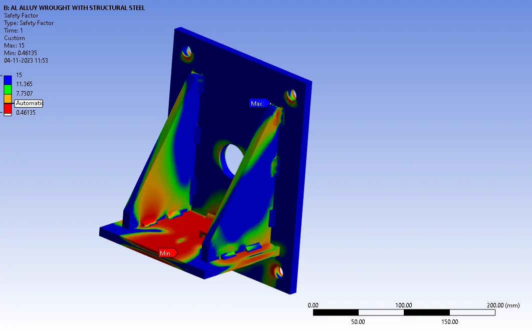
The maximum Safety factor was found to be 0.46 for this stainless steel
CONTACT PRESSURE:
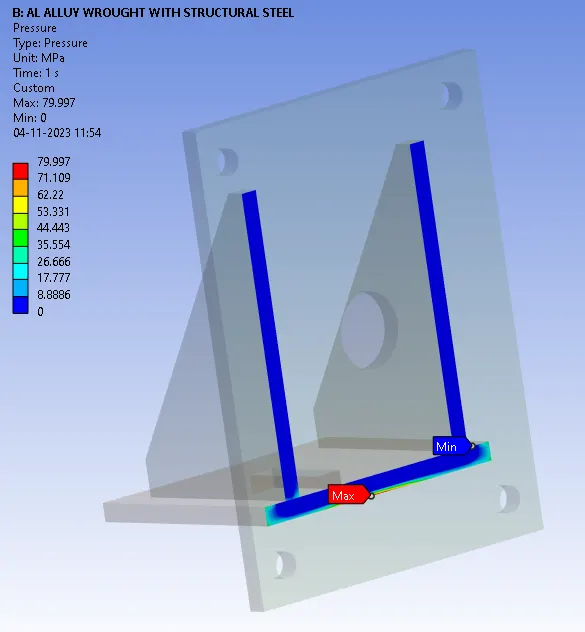
The maximum contact pressure was found to be 80 in the ribs and the bigger plate
Case: 3
Material for Plates: Stainless Steel
Material for Ribs: Bronze
Material for Weld Beads: Copper
Directional Deformation
The maximum total Deformation was found to be 0.39mm
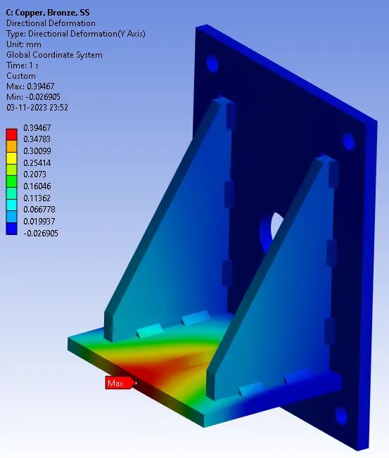
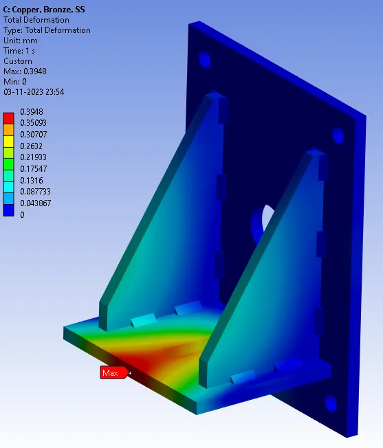
The directional deformation in Y-Axis was found to be similar to total deformation.
The Equivalent (Von-Mises) Stress for the case obtained from the analysis is shown below.
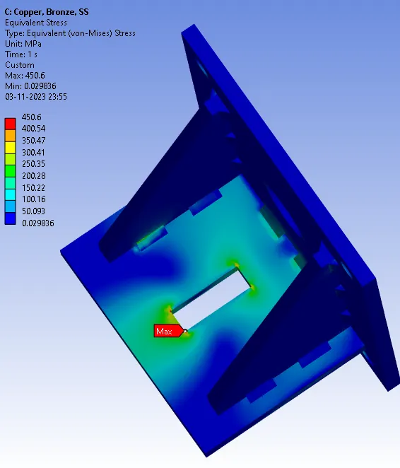
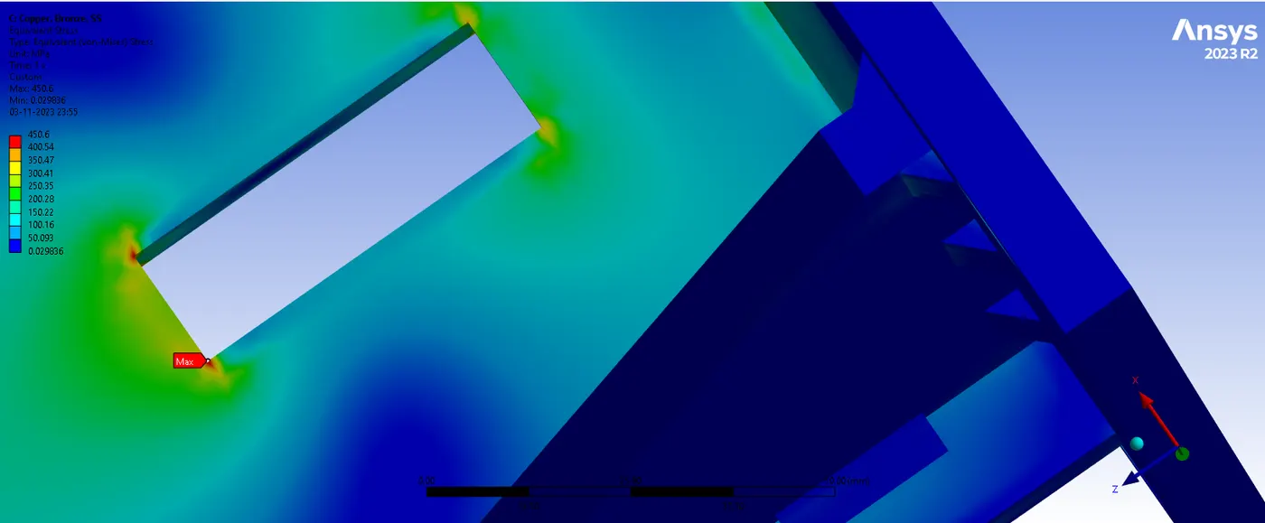
Equivalent Elastic Strain (Ribs)
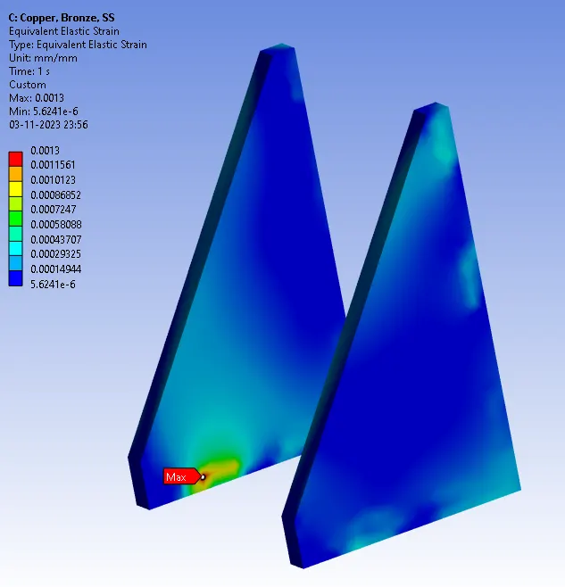
Equivalent Stress (Weld Joints)
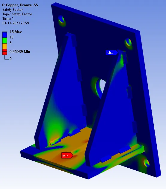
Safety Factor:
The maximum Safety factor was found to be 0.46 for this stainless steel
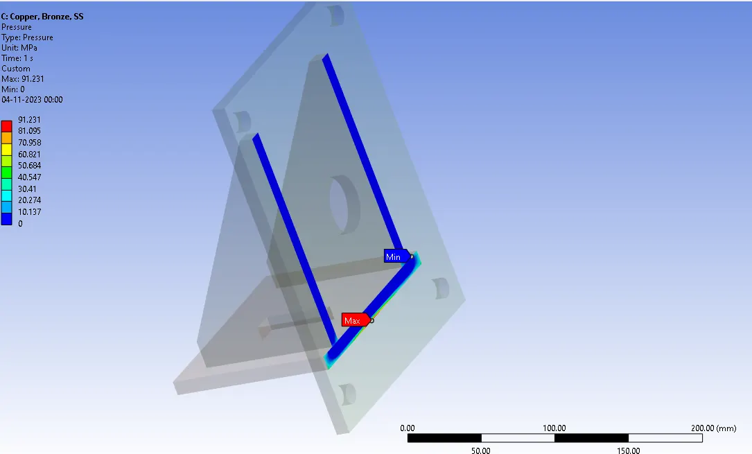
CONTACT PRESSURE:
The maximum contact pressure was found to be 91.2 in the ribs and the bigger plate
Results:
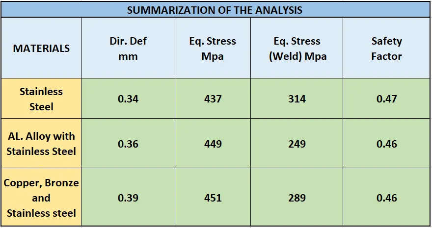
The summarization of the following simulations has been formulated below along with the inferences that has been carried out from the analysis earlier:-
As can be noted from the findings above, case_3's steel plates and stainless steel bronze welds exhibit the most deformation, whereas case_1's stainless steel plates and welds exhibit the least deformation.
The corresponding picture shows the comparable stress produced for each weldment. In the first instance, the stresses that formed on the welds reached their maximum. A resistance to deformation is created by the stresses. Since the structural steel case has the maximum young modulus, the welded joint's stiffness will reduce deformation. This explains why, in comparison with the other two scenarios, the weld material had the least deformation and the greatest produced stresses.
Furthermore, it should be noted that the weld material was deformed in the plastic area because the stresses generated were greater than the structural steel's tensile strength limit (207 Mpa). The ultimate tensile strength (467Mpa) was more than the maximum stress (437 Mpa), however, this prevented cracks from developing.
Compared to stainless steel, aluminum with a lower young modulus deformed more and had fewer stresses resistive to the deformation.
In comparison to the other three weld materials, the bronze weld material had the most deformation, resulting in the lowest strength. It should be more rigid than aluminum, which has a modulus of 73000Mpa, however, aluminum deformed more and created less strength. Aluminum has a modulus of 80000Mpa. This is because, unlike case_3, which had ribs made of copper, case_2's ribs were constructed out of stainless steel. When steel and copper are compared, steel is stronger than copper, therefore steel gave the second case a little more rigidity than copper, which is not stronger than steel.
This variation explains why case_3 bent more than that yet created greater stresses in the weld bronze material than that of the aluminum weld.
Although the case two weld material is weaker than case three, case two is seen to be stiffer than case three during the overall structure's deformation.
Conclusions:
- The maximum stress generated by the weld joint is 249 MPa, and its placement is the same as in the previous scenarios.
- Overall, the welded junction made of an aluminum alloy material obtains less stress than other materials do, while stainless steel deforms less overall than other materials do.
- Aluminum alloy is the highly recommended material for welded joints in this application since the overall deformation does not change significantly.
- Due to its low yield and tensile strength, bronze exhibits higher levels of directed deformation than other materials, and as a result, it cannot support larger loads.
- Because stainless steel has a greater stress distribution than the other two materials, it can support larger loads.
- Stainless steel's equivalent strain is significantly lower than bronze and aluminum, with bronze having intermediate values and aluminum having the highest findings.
- Based on my observations and findings, I have determined that the weld joints where the load is applied—that is, the joint between the small plates and ribs—will experience the most stress. This observation holds true for all three scenarios.
• Taking into account the previous information, the equivalent strain almost always stays the same, varying very slightly between 0.0001 and 0.0004.
• Aluminum exhibits the highest degree of deformation, with structural steel and bronze following suit.
• Structural steel (Case 1) has the highest weld joint stress, followed by aluminum and bronze.
• Taking into account the welds, Case 2 (Aluminum) is the most recommended since every weld has a safety factor greater than 1.